
Issue 03/2019 Art. No. 7001-0070
Operating Manual
Translation of the original operating manual
FED / FED-UL (E2)
Drying and heating ovens
with forced convection and enhanced timer
functions
with microprocessor temperature controller
Model Model version Art. No.
FED 400 (E2) FED400-400V 9010-0216, 9110-0216
FED 400-UL (E2) FED400UL-208V 9010-0217, 9110-0217
FED 720 (E2) FED720-400V 9010-0218, 9110-0218
FED 720-UL (E2) FED720UL-208V 9010-0219, 9110-0219
BINDER GmbH
Address: Post office box 102, 78502 Tuttlingen, Germany Phone: +49 7462 2005 0
Fax: +49 7462 2005 100 Internet: http://www.binder-world.com
E-mail: info@binder-world.com Service Hotline: +49 7462 2005 555
Service Fax: +49 7462 2005 93 555 Service E-Mail: service@binder-world.com
Service Hotline USA: +1 866 885 9794 or +1 631 224 4340 x3
Service Hotline Asia Pacific: +852 390 705 04 or +852 390 705 03
Service Hotline Russia and CIS: +7 495 988 15 16

FED (E2) 03/2019 page 2/57
Content
1. SAFETY .................................................................................................................. 4
1.1 Legal considerations ........................................................................................................................... 4
1.2 Structure of the safety instructions ...................................................................................................... 4
1.2.1 Signal word panel ........................................................................................................................... 4
1.2.2 Safety alert symbol ......................................................................................................................... 5
1.2.3 Pictograms ..................................................................................................................................... 5
1.2.4 Word message panel structure ...................................................................................................... 6
1.3 Localization / position of safety labels on the chamber ....................................................................... 6
1.4 Type plate ............................................................................................................................................ 7
1.5 General safety instructions on installing and operating the chambers ................................................ 8
1.6 Intended use ........................................................................................................................................ 9
1.7 Operating instructions ....................................................................................................................... 10
1.8 Measures to prevent accidents ......................................................................................................... 10
2. CHAMBER DESCRIPTION .................................................................................. 11
2.1 Equipment overview .......................................................................................................................... 12
3. COMPLETENESS OF DELIVERY, TRANSPORTATION, STORAGE, AND
INSTALLATION .................................................................................................... 12
3.1 Unpacking, and checking the equipment and completeness of delivery........................................... 12
3.2 Guidelines for safe lifting and transportation ..................................................................................... 13
3.3 Storage .............................................................................................................................................. 13
3.4 Location of installation and ambient conditions ................................................................................. 14
4. INSTALLATION .................................................................................................... 15
4.1 Electrical connection ......................................................................................................................... 15
4.2 Connection to a suction plant (optional) ............................................................................................ 15
5. START UP ............................................................................................................ 16
5.1 Turning on the chamber .................................................................................................................... 16
5.2 Heating operation display .................................................................................................................. 16
5.3 Air change ......................................................................................................................................... 17
6. CONTROLLER SETTING .................................................................................... 17
6.1 Display / entry of temperature and ventilation set-points (without ramp function) ............................. 17
6.2 Display / entry of temperature and ventilation set-points (with selected temperature ramp) ............ 18
6.3 Time functions: Continuous operation and Timer operation ............................................................. 19
6.3.1 Switching between Continuous operation and Timer operation ................................................... 20
6.3.2 Continuous operation ................................................................................................................... 20
6.3.3 Setting the timer values ................................................................................................................ 21
6.4 User level settings ............................................................................................................................. 22
6.4.1 Temperature unit change between degrees Celsius °C and degrees Fahrenheit °F .................. 23
6.4.2 Enter a temperature ramp ............................................................................................................ 23
6.4.3 Chamber addressing .................................................................................................................... 24
6.4.4 Selecting the timer function .......................................................................................................... 25
6.4.5 Setting the interface mode and, if appropriate, the printer interval .............................................. 26
6.5 Temperature programming example ................................................................................................. 27
6.6 General notes .................................................................................................................................... 27
7. TEMPERATURE SAFETY DEVICES ................................................................... 28
7.1 Temperature safety device class 2 (DIN 12880) ............................................................................... 28
7.2 Temperature safety device class 3.1 (DIN 12880) (option) ............................................................... 29
7.3 Disconnectable audible over-temperature alarm (option) ................................................................. 30

FED (E2) 03/2019 page 3/57
8. OPTIONS .............................................................................................................. 31
8.1 APT-COM™ 4 Multi Management Software (option) ........................................................................ 31
8.2 Data logger kit ................................................................................................................................... 31
8.3 HEPA fresh air filter (option).............................................................................................................. 31
8.4 Analog output for temperature (option) ............................................................................................. 32
9. MAINTENANCE, CLEANING, AND SERVICE ..................................................... 32
9.1 Maintenance intervals, service .......................................................................................................... 32
9.2 Cleaning and decontamination .......................................................................................................... 33
9.2.1 Cleaning ....................................................................................................................................... 33
9.2.2 Decontamination .......................................................................................................................... 35
9.3 Sending the chamber back to BINDER GmbH ................................................................................. 36
10. DISPOSAL ............................................................................................................ 36
10.1 Disposal of the transport packing ...................................................................................................... 36
10.2 Decommissioning .............................................................................................................................. 37
10.3 Disposal of the chamber in the Federal Republic of Germany .......................................................... 37
10.4 Disposal of the chamber in the member states of the EU except for the Federal Republic of
Germany ............................................................................................................................................ 38
10.5 Disposal of the chamber in non-member states of the EU ............................................................... 39
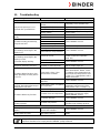
11. TROUBLESHOOTING ......................................................................................... 40
12. TECHNICAL DESCRIPTION ................................................................................ 41
12.1 Factory calibration and adjustment ................................................................................................... 41
12.2 Definition of usable volume ............................................................................................................... 41
12.3 Over current protection...................................................................................................................... 41
12.4 FED technical data ............................................................................................................................ 42
12.5 Equipment and options (extract) ....................................................................................................... 43
12.6 Accessories and spare parts (extract)............................................................................................... 45
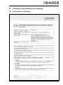
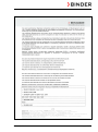
13. CERTIFICATES AND DECLARATIONS OF CONFORMITY ............................... 46
13.1 EU Declaration of Conformity ............................................................................................................ 46
13.2 Certificate for the GS mark of conformity of the “Deutsche Gesetzliche Unfallversicherung e.V.“
(German Social Accident Insurance) DGUV ..................................................................................... 49
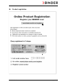
14. PRODUCT REGISTRATION ................................................................................ 51
15. CONTAMINATION CLEARANCE CERTIFICATE ................................................ 52
15.1 For chambers located outside the USA and Canada ........................................................................ 52
15.2 For chambers located in the USA and Canada ................................................................................. 55

FED (E2) 03/2019 page 4/57
Dear customer,
For the correct operation of the chambers, it is important that you read this operating manual completely
and carefully and observe all instructions as indicated. Failure to read, understand and follow the
instructions may result in personal injury. It can also lead to damage to the unit and/or poor equipment
performance.
1. Safety
This operating manual is part of the components of delivery. Always keep it handy for reference. The
device should only be operated by laboratory personnel especially trained for this purpose and familiar
with all precautionary measures required for working in a laboratory. Observe the national regulations on
minimum age of laboratory personnel. To avoid injuries and damage observe the safety instructions of the
operating manual.
WARNING
Failure to observe the safety instructions.
Serious injuries and chamber damage.
Observe the safety instructions in this operating manual.
Carefully read the complete operating instructions of the chamber.
1.1 Legal considerations
This operating manual is for informational purposes only. It contains information for installing, start-up,
operation and maintenance of the product. Note: the contents and the product described are subject to
change without notice.
Understanding and observing the instructions in this operating manual are prerequisites for hazard-free
use and safety during operation and maintenance. In no event shall BINDER be held liable for any
damages, direct or incidental arising out of or related to the use of this manual.
This operating manual cannot cover all conceivable applications. If you would like additional information,
or if special problems arise that are not sufficiently addressed in this manual, please ask your dealer or
contact us directly by phone at the number located on page one of this manual
Furthermore, we emphasize that the contents of this operating manual are not part of an earlier or existing
agreement, description, or legal relationship, nor do they modify such a relationship. All obligations on the
part of BINDER derive from the respective purchase contract, which also contains the entire and
exclusively valid statement of warranty administration. The statements in this manual neither augment nor
restrict the contractual warranty provisions.
1.2 Structure of the safety instructions
In this operating manual, the following safety definitions and symbols indicate dangerous situations
following the harmonization of ISO 3864-2 and ANSI Z535.6.
1.2.1 Signal word panel
Depending on the probability of serious consequences, potential dangers are identified with a signal word,
the corresponding safety color, and if appropriate, the safety alert symbol.
DANGER
Indicates an imminently hazardous situation that, if not avoided, will result in death or serious (irreversible)
injury.

FED (E2) 03/2019 page 5/57
WARNING
Indicates a potentially hazardous situation which, if not avoided, could result in death or serious
(irreversible) injury
CAUTION
Indicates a potentially hazardous situation which, if not avoided, may result in moderate or minor
(reversible) injury
CAUTION
Indicates a potentially hazardous situation which, if not avoided, may result in damage to the product
and/or its functions or of a property in its proximity.
1.2.2 Safety alert symbol
Use of the safety alert symbol indicates a risk of injury.
Observe all measures that are marked with the safety alert symbol in order to avoid death or
injury.
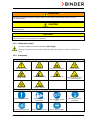
1.2.3 Pictograms
Warning signs
Electrical hazard
Hot surface
Explosive atmosphere
Stability hazard
Lifting hazard
Suffocation hazard
Harmful substances
Risk of corrosion and /
or chemical burns
Biohazard
Pollution Hazard
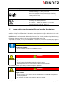
Mandatory action signs
Mandatory regulation
Read operating
instructions
Disconnect the power
plug
Lift with mechanical
assistance
Environment protection
Wear protective gloves
Wear safety goggles

FED (E2) 03/2019 page 6/57
Prohibition signs
Do NOT touch
Do NOT spray with
water
Information to be observed in order to ensure optimum function of the product.
1.2.4 Word message panel structure
Type / cause of hazard.
Possible consequences.
∅ Instruction how to avoid the hazard: prohibition
Instruction how to avoid the hazard: mandatory action
Observe all other notes and information not necessarily emphasized in the same way, in order to avoid
disruptions that could result in direct or indirect injury or property damage.
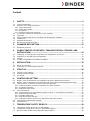
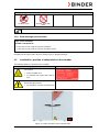
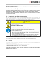
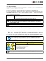
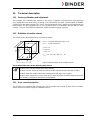
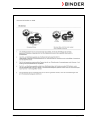
1.3 Localization / position of safety labels on the chamber
The following labels are located on the chamber:
Pictograms (Warning signs)
Service label
Hot surface
• Outer chamber door
• On chamber rear next to the exhaust
duct
Read operating manual
• UL chambers: on outer chamber door
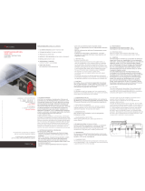
Figure 1: Position of labels on the chamber front

FED (E2) 03/2019 page 7/57
Keep safety labels complete and legible.
Replace safety labels that are no longer legible. Contact BINDER Service for these replacements.
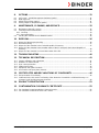
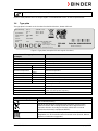
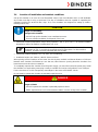
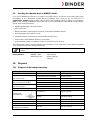
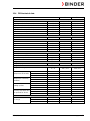
1.4 Type plate
The type plate is located on the chamber front behind the door, bottom left-hand.
Figure 2: Type plate (example: FED 400 regular chamber)
Indications of the type plate
(example)
Information
BINDER
Manufacturer: BINDER GmbH
FED 400
Model designation
Drying and heating oven
Device name
Serial No.
000000000000
Serial no. of the chamber
Built
2019
Year of construction
Nominal temperature
300 °C
572°F
Nominal temperature
IP protection
20
IP type of protection acc. to EN 60529
Temp. safety device
DIN 12880
Temperature safety device acc. to standard DIN 12880
Class
2.0
Class of temperature safety device
Art. No.
9010-0216
Art. no. of the chamber
Project No.
---
Optional: Special application acc. to project no.
3,40 kW
Nominal power
7,4 A
Nominal current
400 V / 50 Hz
Nominal voltage +/- 10%
at the indicated power frequency
400 V / 60 Hz
3 N ~
Current type
Symbol on the type plate
Information
CE conformity marking
Electrical and electronic equipment manufactured / placed on the
market in the EU after 13 August 2005 and to be disposed of in a
separate collection according to Directive 2012/19/EU on waste
electrical and electronic equipment (WEEE).
The chamber is certified according to Customs Union Technical
Regulation (CU TR) for the Eurasian Economic Union (Russia, Belarus,
Armenia, Kazakhstan Kyrgyzstan).
Nominal temp.
300 °C
3,40 kW / 7,4 A
572 °F
400 V / 50 Hz
IP protection
20
400 V / 60 Hz
Safety device
DIN 12880
3 N ~
Class
2.0
Art. No.
9010-0216
Project No.
Built
2019
Drying and heating oven
BINDER GmbH
Im Mittleren Ösch 5
78532 Tuttlingen / Germany
www.binder-world.com
FED 400
E2
Serial No. 00000000000000
Made in Germany

FED (E2) 03/2019 page 8/57
Symbol on the type plate
Information
GS mark of conformity of the “Deutsche Gesetzliche
Unfallversicherung e.V. (DGUV), Prüf- und
Zertifizierungsstelle Nahrungsmittel und Verpackung im
DGUV Test“ (German Social Accident Insurance (DGUV),
Testing and Certification Body for Foodstuffs and Packaging
Industry in DGUV Test).
(Not valid for UL chambers)
(UL chambers only)
The chamber is certified by Underwriters Laboratories Inc.
®
according to the following standards:
UL 61010A-1, 1
st
Edition, UL 61010A-2-10, 1
st
Edition
CSA C22.2 No. 1010.1-92, IEC 1010-2-10
1.5 General safety instructions on installing and operating the chambers
With regard to operating the chambers and to the installation location, please observe the DGUV
guidelines 213-850 on safe working in laboratories (formerly BGI/GUV-I 850-0, BGR/GUV-R 120 or ZH
1/119, issued by the employers’ liability insurance association) (for Germany).
BINDER GmbH is only responsible for the safety features of the chamber provided skilled electricians or
qualified personnel authorized by BINDER perform all maintenance and repair, and if components relating
to chamber safety are replaced in the event of failure with original spare parts.
To operate the chamber, use only original BINDER accessories or accessories from third-party suppliers
authorized by BINDER. The user is responsible for any risk caused by using unauthorized accessories.
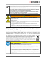
CAUTION
Danger of overheating.
Damage to the chamber.
∅ Do NOT install the chamber in unventilated recesses.
Ensure sufficient ventilation for dispersal of the heat.
Do not operate the chambers in hazardous locations.
DANGER
Explosion hazard.
Danger of death.
∅ Do NOT operate the chamber in potentially explosive areas.
KEEP explosive dust or air-solvent mixtures AWAY from the chamber.
The chambers do not dispose of any measures of explosion protection.
DANGER
Explosion hazard.
Danger of death.
∅ Do NOT introduce any substance into the chamber which is combustible or explosive at
working temperature.
∅ NO explosive dust or air-solvent mixture in the inner chamber.

FED (E2) 03/2019 page 9/57
Any solvent contained in the charging material must not be explosive or inflammable. I.e., irrespective of
the solvent concentration in the steam room, NO explosive mixture with air must form. The temperature
inside the chamber must lie below the flash point or below the sublimation point of the charging material.
Familiarize yourself with the physical and chemical properties of the charging material, as well as the
contained moisture constituent and its behavior with the addition of heat energy.
Familiarize yourself with any potential health risks caused by the charging material, the contained moisture
constituent or by reaction products that may arise during the temperature process. Take adequate
measures to exclude such risks prior to putting the chamber into operation.
DANGER
Electrical hazard.
Danger of death.
∅ The chamber must NOT become wet during operation or maintenance.
The chambers were produced in accordance with the VDE regulations and were routinely tested in
accordance to VDE 0411-1 (IEC 61010-1).
During and shortly after operation, the temperature of the inner surfaces almost equals the set-point.
CAUTION
The inner chamber, the exhaust duct, the door window (option), the door gaskets,
and the access ports will become hot during operation.
Danger of burning.
∅ Do NOT touch the inner surfaces, the exhaust duct, the door window, the access ports,
the door gaskets, or the charging material during operation.
1.6 Intended use
The chambers are suitable for exact tempering of harmless materials and for drying and heat treatment of
solid or pulverized charging material, as well as bulk material, using the supply of heat. They can be used
to dry e.g. glassware, and for warm storage of liquids in containers.
A solvent content must not be explosive or flammable. A mixture of any component of the charging
material with air must NOT be explosive. The operating temperature must lie below the flash point or
below the sublimation point of the charging material. Any component of the charging material must NOT
be able to release toxic gases
Other applications are not approved.
The chambers are not classified as medical devices as defined by the Medical Device Directive
93/42/EEC.
Do NOT use the chamber for drying processes when large quantities of vapor would form and result in
condensation.
Due to the special demands of the Medical Device Directive 93/42/EEC, these chambers are
not qualified for sterilization of medical devices as defined by the directive.
Observing the instructions in this operating manual and conducting regular maintenance work
(chap. 9) is part of the intended use.
WARNING: If customer should use a BINDER chamber running in non-supervised continuous
operation, we strongly recommend in case of inclusion of irrecoverable specimen or samples
to split such specimen or samples and store them in at least two chambers, if this is feasible.

FED (E2) 03/2019 page 10/57
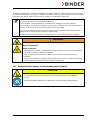
The charging material shall not contain any corrosive ingredients that may damage the
machine components. Such ingredients include in particular acids and halides. Any corrosive
damage caused by such ingredients is excluded from liability by BINDER GmbH.
The chambers do not dispose of any measures of explosion protection.
DANGER
Explosion or implosion hazard.
Danger of poisoning.
Danger of death.
∅ Do NOT introduce any substance combustible or explosive at working temperature into
the chamber, in particular no energy sources such as batteries or lithium-ion batteries.
∅ NO explosive dust or air-solvent mixture in the inner chamber.
∅ Do NOT introduce any substance which could lead to release of toxic gases.
In case of foreseeable use of the device there is no risk for the user through the integration of the
chamber into systems or by special environmental or operating conditions in the sense of EN 61010-
1:2010. For this, the intended use of the chamber and all its connections must be observed.
1.7 Operating instructions
Depending on the application and location of the chamber, the operator of the chamber must provide the
relevant information for safe operation of the chamber in a set of operating instructions.
Keep these operating instructions with the chamber at all times in a place where they are
clearly visible. They must be comprehensible and written in the language of the employees.
1.8 Measures to prevent accidents
The manufacturer took the following measures to prevent ignition and explosions:
• Indications on the type plate
See operating manual chap. 1.4.
• Operating manual
An operating manual is available for each chamber.
• Overtemperature monitoring
The chamber is equipped with a temperature display, which can be read from outside.
The chamber is equipped with an additional safety controller (temperature safety device class 2 acc. to
DIN 12880:2007). Visual and audible (buzzer) signals indicate temperature exceeding.
• Safety, measurement, and control equipment
The safety, measuring, and control equipment is easily accessible.
• Electrostatic charge
The interior parts are grounded.

FED (E2) 03/2019 page 11/57
• Non-ionizing radiation
Non-ionizing radiation is not intentionally produced, but released only for technical reasons by electrical
equipment (e.g. electric motors, power cables, solenoids). The machine has no permanent magnets. If
persons with active implants (e.g. pacemakers, defibrillators) keep a safe distance (distance of field
source to implant) of 30 cm, an influence of these implants can be excluded with high probability.
• Protection against touchable surfaces
Tested according to EN ISO 13732-1:2008.
• Floors
See operating manual chap. 3.4 for correct installation
• Cleaning
See operating manual chap. 9.2.
• Examinations
The chamber has been inspected by the “Deutsche Gesetzliche Unfallversicherung e.V. (DGUV)
(German Social Accident Insurance (DGUV)” (German Social Accident Insurance (DGUV), Testing
and Certification Body for Foodstuffs and Packaging Industry in DGUV Test) and bears the GS mark.
(Not valid for UL chambers)
UL chambers only: The chamber is certified by Underwriters Laboratories Inc.
®
according to the
standards UL 61010A-1, 1st Edition, UL 61010A-2-10, 1st Edition, CSA C22.2 No. 1010.1-92, IEC
1010-2-10.
2. Chamber description
BINDER drying and heating ovens FED are equipped with an electronic PID-controller with digital display.
The temperature is indicated with an accuracy of one degree.
The chambers are heated electrically and are ventilated by fan-assisted, forced-air circulation. They FED
are equipped with a temperature safety device according to DIN12880 (chap. 7).
The APT.line™ preheating chamber system guarantees high level of spatial and time-based temperature
precision, thanks to the direct and distributed air circulation into the interior. The fan supports exact
attainment and maintenance of the desired temperature accuracy.
The chambers are regularly equipped with a temperature safety device according to DIN12880:2007
(chap. 7).
The inner chamber, the pre-heating chamber and the inside of the doors are all made of stainless steel
V2A (German material no. 1.4301, US equivalent AISI 304). When operating the chamber at temperatures
above 150 °C, the impact of the oxygen in the air may cause discoloration of the metallic surfaces
(yellowish-brown or blue) by natural oxidation processes. These colorations are harmless and will in no
way impair the function or quality of the chamber. The housing is RAL 7035 powder-coated. All corners
and edges are also completely coated.
All chamber functions are easy and comfortable to use thanks to their clear arrangement. Major features
are easy cleaning of all chamber parts and avoidance of undesired contamination.
The chambers are equipped with a serial interface RS 422 for computer communication, e.g. via the APT-
COM™ 4 Multi Management Software (option, chap. 8.1). For further options, see chap. 12.5.
The model FED 720 is equipped with
four castors. Both front castors can be locked by brakes.
The chamber can be operated in a temperature range of 5 °C / 9 °F above room temperature up to 300 °C
/ 572 °F.

FED (E2) 03/2019 page 12/57
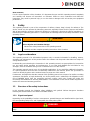
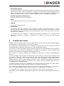
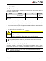
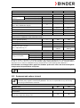
2.1 Equipment overview
(1) Display
(2) Set-point value key
(3) Selector keys
(4) Time management key
(5) Switch ON/OFF
(6) Lever for ventilation slide
(7) Safety device
(8) Door handle
(9) Switch for interior lighting (with
option interior lighting) or
Buzzer switch (with option
audible over-temperature alarm)
(10) Main power switch
Figure 3: FED drying and heating oven
3. Completeness of delivery, transportation, storage, and
installation
3.1 Unpacking, and checking the equipment and completeness of delivery
After unpacking, please check the chamber and its optional accessories, if any, based on the delivery
receipt for completeness and for transportation damage. Inform the carrier immediately if transportation
damage has occurred.
The final tests of the manufacturer may have caused traces of the racks on the inner surfaces. This has
no impact on the function and performance of the chamber.
Please remove any transportation protection devices and adhesives in/on the chamber and on the doors
and take out the operating manuals and accessory equipment.
CAUTION
Sliding or tilting the chamber.
Damage to the chamber.
Risk of injury by lifting heavy loads.
∅ Do NOT lift or transport the chamber using the door handle or the door.
∅ Do NOT lift chambers by hand
Lift chambers from the pallet using technical devices (fork lifter). Set the fork lifter only
from the rear in the middle of the chamber. Make sure to place all the lateral supports
of the chamber on the forks.
(6)
(9)
(7)
(8)
(10)
(1)
(2)
(3)
(4)
(5)

FED (E2) 03/2019 page 13/57
If you need to return the chamber, please use the original packing and observe the guidelines for safe
lifting and transportation (chap. 3.2).
For disposal of the transport packing, see chap. 10.1.
Note on second-hand chambers (Ex-Demo chambers):
Second-hand chambers have been used for a short time for tests or exhibitions. They are thoroughly
tested before resale. BINDER ensures that the chamber is technically sound and will work flawlessly.
Second-hand chambers are marked with a sticker on the chamber door. Please remove the sticker before
commissioning the chamber.
3.2 Guidelines for safe lifting and transportation
The front castors of chambers size 720 can be blocked by brakes. Please move the chambers with
castors only when empty and on an even surface, otherwise the castors may be damaged. After operation
please observe the guidelines for temporarily decommissioning the chamber (chap. 10.2).
CAUTION
Sliding or tilting the chamber.
Damage to the chamber.
Risk of injury by lifting heavy loads.
Transport the chamber only in its original packaging.
Secure the chamber with transport straps for transport.
∅ Do NOT lift or transport the chamber using the door handle or the door.
∅ Do NOT lift chambers by hand.
Place chambers using technical devices (fork lifter) on the transport pallet. Set the fork
lifter only from the rear in the middle of the chamber. Make sure to place all the lateral
supports of the chamber on the forks.
Transport chambers ONLY with the original transport pallet. Set the fork lifter only to
the pallet. Without the pallet the chamber is in imminent danger of overturning!!
• Permissible ambient temperature range during transport: -10 °C to +60 °C.
You can order transport packing and pallets for transportation purposes from BINDER Service.
3.3 Storage
Intermediate storage of the chamber is possible in a closed and dry room. Observe the guidelines for
temporary decommissioning (chap. 10.2).
• Permissible ambient temperature range during storage: -10 °C to +60 °C.
• Permissible ambient humidity: max. 70 % r.H., non-condensing
When after storage in a cold location you transfer the chamber to its warmer installation site,
condensation may form. Before start-up, wait at least one hour until the chamber has attained ambient
temperature and is completely dry.

FED (E2) 03/2019 page 14/57
3.4 Location of installation and ambient conditions
Set up the chamber on an even and non-flammable surface, free from vibration and in a well-ventilated,
dry location and align it using a spirit level. The site of installation must be capable of supporting the
chamber’s weight (see technical data, chap. 12.4). The chambers are designed for setting up inside a
building (indoor use).
CAUTION
Danger of overheating.
Damage to the chamber.
∅ Do NOT set up the chamber in non-ventilated recesses.
Ensure sufficient ventilation for dispersal of the heat.
• Permissible ambient temperature range during operation: +18 °C up to +40 °C. At elevated ambient
temperature values, fluctuations in temperature can occur.
The ambient temperature should not be substantially higher than the indicated ambient
temperature of +25 °C to which the specified technical data relate. For other ambient
conditions, deviations from the indicated data are possible.
• Permissible ambient humidity: 70 % r.H. max., non-condensing.
• Installation height: max. 3000 m / 9842 ft. above sea level.
When placing several chambers of the same size side by side, maintain a minimum distance of 250 mm
between each chamber. Wall distances: rear 100 mm, sides 160 mm. Spacing above the chamber of at
least 100 mm must also be accounted for.
To completely separate the chamber from the power supply, you must disconnect the power plug. Install
the chamber in a way that the power plug is easily accessible and can be easily pulled in case of danger.
For the user there is no risk of temporary overvoltages in the sense of EN 61010-1:2010.
Do not install or operate the chamber in potentially explosive areas.
DANGER
Explosion hazard.
Danger of death.
∅ Do NOT operate the chamber in potentially explosive areas.
KEEP explosive dust or air-solvent mixtures AWAY from the vicinity of the chamber.

FED (E2) 03/2019 page 15/57
4. Installation
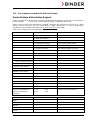
4.1 Electrical connection
The chambers are supplied ready for connection. They come with a fixed power connection cable of at
least 1800 mm / 70.87 in in length.
Model Power plug
Nominal voltage
±
10% at the
indicated power frequency
Current type
FED 400
FED 720
CEE plug 5-polig
400 V at 50 Hz
400 V at 60 Hz
3N~
FED 400-UL
FED 720-UL
NEMA L21-20P 208 V at 60 Hz 3N~
• The domestic socket must also provide a protective conductor. Make sure that the connection of the
protective conductor of the domestic installations to the chamber’s protective conductor meets the
latest technology. The protective conductors of the socket and plug must be compatible!
• Prior to connection and start-up, check the power supply voltage. Compare the values to the specified
data located on the chamber‘s type plate (chamber front behind the door, bottom left-hand, chap. 1.4).
• When connecting, please observe the regulations specified by the local electricity supply company and
as well as the VDE directives (for Germany). We recommend the use of a residual current circuit
breaker.
• Pollution degree (acc. to IEC 61010-1): 2
• Over-voltage category (acc. to IEC 61010-1): II
CAUTION
Danger of incorrect power supply voltage.
Damage to the equipment.
Check the power supply voltage before connection and start-up.
Compare the power supply voltage with the data indicated on the type plate.
See also electrical data (chap.12.4).
To completely separate the chamber from the power supply, you must disconnect the power
plug. Install the chamber in a way that the power plug is easily accessible and can be easily
pulled in case of danger.
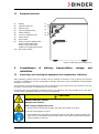
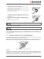
4.2 Connection to a suction plant (optional)
When directly connecting a suction plant the spatial temperature exactitude, the heating-up and the
recovering times and the maximum temperature will be negatively influenced. So no suction plant should
be directly connected to the exhaust duct.
Active suction from the chamber must only be performed together with extraneous air.
Perforate the connecting piece to the suction device or place an exhaust funnel at some
distance to the exhaust duct.

FED (E2) 03/2019 page 16/57
CAUTION
The exhaust duct will become hot during operation.
Danger of burning.
∅ Do NOT touch the exhaust duct during operation.
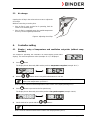
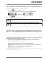
5. Start up
5.1 Turning on the chamber
Warming chambers may release odors in the first few days after commissioning. This is not a
quality defect. To reduce odors quickly we recommend heating up the chamber to its nominal
temperature for one day and in a well-ventilated location.
1. Insert the power plug into a suitable socket (chap. 4.1).
2. Turn on chambers at the main power switch (10)
The green “Standby“ LED illuminates.
3. Press
until the display lights up.
The controller is now in normal display (actual value display).
If the chamber is operating (time functions “Continuous operation”, or
“Timer operation” with the set time just running down chap. 6.3), the actual
temperature value (example: 22 °C) is displayed
If the chamber is in time function “Timer operation” with no time programmed or the set time run-off (chap.
6.3), the chamber is inactive (no heating). The display alternately shows the actual temperature value
(example: 22 °C) and “tOff”:
Adjust the temperature safety device following any changes of the set-point (chap. 7).
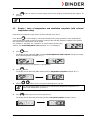
5.2 Heating operation display
The heating is active as soon as the red heating control light in the
bottom right corner of the display slowly begins to flash depending on the
heat requirement (example: 70 °C):

FED (E2) 03/2019 page 17/57
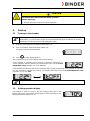
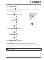
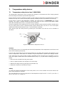
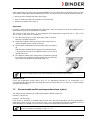
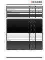
5.3 Air change
Opening the air flap in the exhaust duct serves to adjust the
air change.
Without connecting a suction plant:
• If the air flap is open and the fan is operating, fresh air
comes in via aeration gaps.
• If the air flap is completely open, the spatial temperature
accuracy can be negatively influenced.
Figure 4: Adjusting the air flap
6. Controller setting
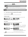
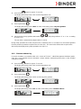
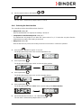
6.1 Display / entry of temperature and ventilation set-points (without ramp
function)
The chamber is operating, the controller is in normal display (actual value
display). The actual temperature value (example: 22 °C) is displayed:
1. Press
button
The display shows alternately “SP” and the previous temperature set-point (example: 60 °C):
2. With the
buttons enter a set-point value between 0 and 300.
The desired temperature set-point can be selected in a temperature range from 5 °C
above room temperature up to 300 °C.
Wait 2 seconds until the entered temperature value is taken over (display flashing once).
3. Press
button to proceed to the fan speed entry.
The display shows alternately “n” and the previous fan speed set-point (example: 100%):
4. Set the desired fan speed with the
buttons.
The fan speed can be set to a value between 0% and 100%.
Wait 2 seconds until the entered value is taken over (display flashing once).

FED (E2) 03/2019 page 18/57
5. Press
button to return to normal display (actual value display) (automatically after approx. 30
seconds).
Adjust the temperature safety device following any changes of the set-point (chap. 7).
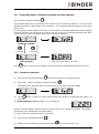
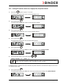
6.2 Display / entry of temperature and ventilation set-points (with selected
temperature ramp)
If previously a temperature ramp value has been selected (chap. 6.4.2):
Press button
in normal display / actual value display during ramp operation to have displayed the
actual temperature ramp set-point changing according to the selected gradient in addition to the entered
final set-points for temperature and fan speed.
The chamber is operating, the controller is in normal display (actual value
display). The actual temperature value (example: 22 °C) is displayed:
1. Press
button
The display shows alternately “SPr” and the actual temperature ramp set-point changing according
to the selected gradient (example: 42 °C):
This ramp set-point is only displayed, not adjustable.
2. Press
button
The display shows alternately “SP” and the previous temperature set-point (example: 60 °C):
3. With the
buttons enter a set-point value between 0 and 300.
The desired temperature set-point can be selected in a temperature range from 5 °C
above room temperature up to 300 °C.
Wait 2 seconds until the entered temperature value is taken over (display flashing once).
4. Press
button to proceed to the fan speed entry.
The display shows alternately “n” and the previous fan speed set-point (example: 100%):

FED (E2) 03/2019 page 19/57
5. Set the desired fan speed with the
buttons
The fan speed can be set to a value between 0% and 100%.
Wait 2 seconds until the entered value is taken over (display flashing once).
6. Press
button to return to normal display / actual value display (automatically after approx. 30
seconds).
Adjust the temperature safety device following any changes of the set-point (chap. 7).
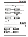
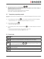
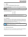
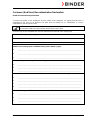
6.3 Time functions: Continuous operation and Timer operation
Press the time management button .
The timer indicates its current time function. There are two possible time functions:
Continuous operation
The display shows alternately “t1” (time function) and the time function “Continuous operation” “t inf”:
The heating is permanently active, independent of the timer setting.
Timer operation
The display shows alternately “t1” (time function) and the running-down time or “tOff”:
or
Remaining time (example: 28 Min.) –
Timer running
down
Heating activity depending on the entered time value and
the timer function selected in the user menu (chap.6.4.4)
Timer not programmed or run-down “t off”
If the timer has run-down, the chamber’s behavior depends
on the pre-selected timer function (chap. 6.4.4).
Press
button to return to normal display (actual value display) (automatically after approx. 30
seconds).

FED (E2) 03/2019 page 20/57
6.3.1 Switching between Continuous operation and Timer operation
Press the time management button .
The controller displays the actual time function. In time function “Continuous operation”, “t1” and “t inf” are
displayed alternately. In time function “Timer operation”, “t1” is displayed alternately with the running-down
time or “tOff”.
If in time function “Timer operation” the Timer is just running off (“t1”displayed alternately with the running-
down time) the timer must at first be set to Zero (chap. 6.3.3). Now “t1” is displayed alternately with “tOff”,
and the controller can be changed to time function “Continuous operation”.
Continuous operation
2 seconds
2 seconds
Timer operation
Timer not programmed or run-down
Press
button to return to normal display / actual value display (automatically after approx. 30 sec).
6.3.2 Continuous operation
1. Press the time management button .The timer indicates its current time function.
2. If necessary, switch to Continuous operation by button .
The display shows alternately “t1” and the time function “Continuous operation” “t inf”:
3. Press
button to return to normal display (actual value display) (automatically after approx. 30
seconds).
The actual temperature value (example: 22 °C) is displayed:
Now the controller operates with the entered set-points (chap. 6.1) in continuous operation. The heating is
permanently active, independent of the timer setting.
To cancel Continuous operation, proceed accordingly:
1. Press the time management button
.
2. Switch to Timer operation by pressing down button for 2 seconds (chap. 6.3.1).
Seite wird geladen ...
Seite wird geladen ...
Seite wird geladen ...
Seite wird geladen ...
Seite wird geladen ...
Seite wird geladen ...
Seite wird geladen ...
Seite wird geladen ...
Seite wird geladen ...
Seite wird geladen ...
Seite wird geladen ...
Seite wird geladen ...
Seite wird geladen ...
Seite wird geladen ...
Seite wird geladen ...
Seite wird geladen ...
Seite wird geladen ...
Seite wird geladen ...
Seite wird geladen ...
Seite wird geladen ...
Seite wird geladen ...
Seite wird geladen ...
Seite wird geladen ...
Seite wird geladen ...
Seite wird geladen ...
Seite wird geladen ...
Seite wird geladen ...
Seite wird geladen ...
Seite wird geladen ...
Seite wird geladen ...
Seite wird geladen ...
Seite wird geladen ...
Seite wird geladen ...
Seite wird geladen ...
Seite wird geladen ...
Seite wird geladen ...
Seite wird geladen ...
-
 1
1
-
 2
2
-
 3
3
-
 4
4
-
 5
5
-
 6
6
-
 7
7
-
 8
8
-
 9
9
-
 10
10
-
 11
11
-
 12
12
-
 13
13
-
 14
14
-
 15
15
-
 16
16
-
 17
17
-
 18
18
-
 19
19
-
 20
20
-
 21
21
-
 22
22
-
 23
23
-
 24
24
-
 25
25
-
 26
26
-
 27
27
-
 28
28
-
 29
29
-
 30
30
-
 31
31
-
 32
32
-
 33
33
-
 34
34
-
 35
35
-
 36
36
-
 37
37
-
 38
38
-
 39
39
-
 40
40
-
 41
41
-
 42
42
-
 43
43
-
 44
44
-
 45
45
-
 46
46
-
 47
47
-
 48
48
-
 49
49
-
 50
50
-
 51
51
-
 52
52
-
 53
53
-
 54
54
-
 55
55
-
 56
56
-
 57
57


in anderen Sprachen
Verwandte Artikel
-
Binder BF 400 Bedienungsanleitung
-
Binder B 28 Bedienungsanleitung
-
Binder BD 720 Bedienungsanleitung
-
-
-
-
-
-
Andere Dokumente
-
 Memmert SN PLUS Operating Instructions Manual
-
 Memmert IN Operating Instructions Manual
-
Amica AR1112R Bedienungsanleitung
-
Robomow RS622 (Up to 1/2 Acre) Bedienungsanleitung
-
Hama 00087697 Bedienungsanleitung
-
Liebherr SUFsg 5001 Bedienungsanleitung
-
 Thermo Fisher Scientific Dionex UltiMate 3000 Series Bedienungsanleitung
-
 Asutec ASREL-003 Assembly Instruction


