
Bedienungsanleitung
Instruction manual
ba55319de03
07/00
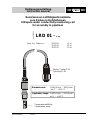
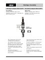
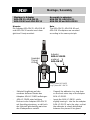
Reinstwasser-Leitfähigkeitsmeßzelle
zum Einbau in Rohrleitungen
Ultrapure water conductivity measuring cell
for assembly in pipelines
LRD 01 - ...
Best.-Nr./ Order no.: 302 220 1.5 m
302 221 3.0 m
302 222 7.0 m
Temperaturmeßfühler
Temperature probe
Stecker 7-polig IP 65
7-pin plug IP 65
Einsatzbereich:
0,001 µS/cm … 200 µS/cm
bei -5 … +130 °C
Application range:
0.001 µS/cm … 200 µS/cm
at -5 … +130 °C
ba55319de

Inhaltsverzeichnis / Contents
2
Sicherheitshinweise ................................................................................................ 3
Montage .................................................................................................................... 3
Montagehinweis ................................................................................................... 3
Montage in Edelstahladapter ............................................................................... 4
Montage in Kunststoffadapter .............................................................................. 7
Steckerbelegung ................................................................................................... 11
Technische Daten .................................................................................................. 13
Betrieb / Wartung ................................................................................................... 15
Reinigung ........................................................................................................... 15
Alterung ............................................................................................................. 16
Entsorgung ........................................................................................................ 16
Zubehör .................................................................................................................. 17
Edelstahladapter ................................................................................................ 17
Kunststoffadapter ............................................................................................... 17
Garantieerklärung
Safety guidelines ..................................................................................................... 3
Assembly ................................................................................................................. 3
Assembly note ..................................................................................................... 3
Assembly in stainless steel adapters ................................................................... 4
Assembly in plastic adapters ............................................................................... 7
Pin assignment ...................................................................................................... 11
Technical data ....................................................................................................... 14
Operation / Maintenance ....................................................................................... 15
Cleaning ............................................................................................................. 15
Aging .................................................................................................................. 16
Disposal ............................................................................................................. 16
Accessories ........................................................................................................... 17
Stainless steel adapters ..................................................................................... 17
Plastic adapters ................................................................................................. 17
Warranty

Sicherheitshinweise / Safety guidelines
Montage / Assembly
3
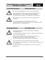
Sicherheitshinweise Safety guidelines
Bei allen Wartungsarbeiten den Sensor vom Gerät abziehen!
Der Kontakt mit der Meßlösung kann zu einer Gefährdung des
Anwenders führen. Je nach Art der Meßlösung geeignete
Schutzmaßnahmen ergreifen (Schutzkleidung, Schutzbrille etc.).
For all maintenance operations disconnect the probe from the
instrument!
The measuring solution may be dangerous for the user.
Take protective measures suitable for the kind of measuring solution
(protective clothes, eye protectors etc.).
Montagehinweise Assembly notes
Die Montage darf nur von hierfür ausgebildeten Fachkräften
durchgeführt werden.
Für unsachgemäße Installation und deren Folgen wird vom Hersteller
keine Garantie übernommen.
Die Technischen Regeln für Druckbehälter (DruckbehV) und
Dampfkessel beachten (in anderen Ländern gelten
jeweils die entsprechenden internationalen Verordnungen).
The assembly may only be performed by trained specialists.
The manufacturer’s warranty does not cover improper installation and
its consequences.
Observe the legal technical regulations for pressure vessels and
steam boilers.

Montage / Assembly
4
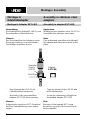
Montage in
Edelstahladapter
Assembly in stainless steel
adapters
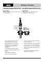
Montage in Adapter EST-LRD Assembly in adapter EST-LRD
Verwendung:
Einschweißmuffe (Edelstahl 1.4571) zum
Verschweißen in Edelstahlrohre.
Hinweis:
Das Einschweißen des Adapters sowie
Rohrausschnitte nur von autorisierten
Fachkräften ausführen lassen.
Application:
Welding sleeve (stainless steel 1.4571) to
be welded into stainless steel pipes.
Note:
Only authorized specialists should weld
the adapter and make the cutouts in the
pipes.
Gewinde/
Thread
LRD 01
Adapter
EST-LRD
Rohr/Pipe
– Das Gewinde der LRD 01 mit
Teflondichtband umwickeln.
– Meßzelle in den verschweißten
Adapter EST-LRD festschrauben.
Hinweis:
Aufgrund des konischen NPT-Gewindes
muß die Gewindeöffnung nach außen
zeigen!
– Tape the thread of the LRD 01 with
teflon sealing tape.
– Screw the measuring cell tight into
the welded adapter EXT-LRD.
Note:
Because of the tapered NPT screw
thread the opening of the thread has to
show outwards!

Montage / Assembly
5
Montage in Adapter ADA-3/4 NPT Assembly in adapter ADA-3/4 NPT
Verwendung:
Adapter (Edelstahl 1.4571) zum
Vergrößern des 1/2“ NPT-Gewindes der
LRD 01 auf 3/4“ NPT.
Application:
Adapter (stainless steel 1.4571) to
enlarge the 1/2“ NPT thread of the
LRD 01 to a 3/4“ NPT.
Gewinde/
Thread
LRD 01
Adapter
ADA-3/4 NPT
– Das Gewinde der LRD 01 mit
Teflondichtband umwickeln.
– Den Adapter mit der Gewinde-
öffnung nach oben zeigend auf das
Meßzellengewinde aufschrauben.
– Den Adapter mit einem Gabel-
schlüssel, Schlüsselweite 24 fest-
ziehen.
– Meßzelle mit Adapter in
entsprechenden Rohrausschnitt
einschrauben.
– Tape the thread of the LRD 01 with
teflon sealing tape.
– Screw the adapter on the thread of
the measuring cell – the thread
opening of the adapter has to show
upwards.
– Tighten the adapter using a size 24
fork wrench.
– Screw the measuring cell with
adapter into the corresponding pipe
cutout.

Montage / Assembly
6
Montage in Adapter ADA-G1 Zoll Assembly in adapter ADA-G1 inch
Verwendung:
Adapter (Edelstahl 1.4571) zum Einbau in
1“-Rohrgewinde.
Application:
Adapter (stainless steel 1.4571) for
assembly in 1“ pipe thread.
Gewinde/
Thread
LRD 01
Adapter
ADA-G1 Zoll
ADA-G1 inch
– Das Gewinde der LRD 01 mit
Teflondichtband umwickeln.
– Den Adapter mit der Gewinde-
öffnung nach oben zeigend im
Rohrgewinde auf Anschlag
montieren.
– Den Adapter mit einem Gabel-
schlüssel, Schlüsselweite 41 fest-
ziehen.
– Die Meßzelle in Adapter
ADA-G1 Zoll einschrauben.
– Tape the thread of the LRD 01 with
teflon sealing tape.
– Mount the adapter in the pipe thread
up to the stop – the thread opening
of the adapter has to show upwards.
– Tighten the adapter using a size 41
fork wrench.
– Screw the measuring cell into the
ADA-G1 inch adapter.

Montage / Assembly
7
Montage in
Kunststoffadapter
Assembly in plastic adapters
Verwendung:
Die Kunststoffadapter (PVC-U) werden in
PVC-Kunststoffrohren eingeklebt,
vorzugsweise in T-Stück 90° oder
Kreuzstück 90°.
Hinweis:
Bevor man PVC-Klebstoff (z. B. Tangit,
Fa. Henkel) auf die Adapter aufbringt
müssen die Flächen vorher gut gereinigt
und entfettet sein.
Den Klebstoff - nach Herstellerangaben
für Klebstoff - aushärten lassen.
Application:
The plastic adapters (PVC-U) are glued
into PVC plastic pipes, preferably into a
90° T-piece or 90° crosspiece.
Note:
Before depositing adhesive (e. g. Tangit,
Henkel company) on the adapter, the
areas must be thoroughly cleaned and
degreased.
Let the adhesive harden – according to
the instructions of the adhesive
manufacturer.

Montage / Assembly
8
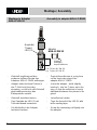
Montage in Adapter
ADA-LF-DN 20
Assembly in adapter ADA-LF-DN20
Gewinde/
Thread
LRD 01
Klebstoff
auftragen/
deposit adhesive
Adapter
ADA-LF-DN 20
z. B. T-Stück 90° DN 20/
e.g. T-piece 90° DN 20
– Klebstoff ringförmig auf den
vorderen äußeren Absatz des
Adapters ADA-LF-DN20 aufbringen.
– Adapter unter leichtem Drehen in
das T-Stück auf Anschlag
einsetzen, so daß sich der Klebstoff
gleichmäßig zwischen den
Klebepartnern verteilt.
– Klebstoff aushärten lassen.
– Das Gewinde der LRD 01 mit
Teflondichtband umwickeln.
– Die Meßzelle in den Adapter
fest einschrauben.
– Deposit the adhesive in a ring form
on the front outer step of the
adapter ADA-LF-DN20.
– Insert the adapter - while slightly
turning it - into the T-piece up to the
stop, so that the adhesive is evenly
distributed between the pieces to be
glued.
– Let adhesive harden.
– Tape the thread of the LRD 01 with
teflon sealing tape.
– Screw the measuring cell tightly into
the adapter.

Montage / Assembly
9
Montage in Adapter
ADA-DN 25, ADA-DN 32,
ADA-DN 40 und ADA-DN 50
Assembly in adapters
ADA-DN 25, ADA-DN 32,
ADA-DN 40 and ADA-DN 50
Hinweis:
Die Adapter ADA-DN 25, ADA-DN 40
und ADA-DN 50 werden nach dem
gleichen Prinzip montiert.
Note:
The ADA-DN 25, ADA-DN 40 und
ADA-DN 50 adapters are mounted
according to the same principle.
Gewinde/
Thread
LRD 01
z.B. T-Stück 90° DN 32
e.g. T-piece 90° DN 32
Adapter:
und/and
ADA-LF-DN 20
ADA-DN 32
– Klebstoff ringförmig auf den
vorderen äußeren Absatz des
Adapters ADA-LF-DN20 aufbringen.
– ADA-LF-DN20 unter leichtem
Drehen in den Adapter ADA-DN 32
auf Anschlag einsetzen, so daß sich
der Klebstoff gleichmäßig zwischen
den Klebepartnern verteilt.
– Deposit the adhesive in a ring form
on the front outer step of the adapter
ADA-LF-DN20.
– Insert the ADA-LF-DN20 - while
slightly turning it - into the the adapter
ADA-LF-DN 32 up to the stop, so that
the adhesive is evenly distributed
between the pieces to be glued.

Montage / Assembly
10
– Klebstoff aushärten lassen.
– PVC-Klebstoff ringförmig auf den
äußeren vorderen Absatz des
Adapters ADA-DN 32 aufbringen.
– Adapter unter leichtem Drehen in
das T-Stück einsetzen, so daß sich
der Klebstoff gleichmäßig zwischen
den Klebepartnern verteilt.
– Klebstoff aushärten lassen.
– Das Gewinde der LRD 01 mit
Teflondichtband umwickeln.
– Die Meßzelle in den Adapter
fest einschrauben.
– Let adhesive harden.
– Deposit the PVC adhesive in a ring
form on the front outer step of the
adapter ADA-DN 32.
– Insert the adapter - while slightly
turning it - into the T-piece so that the
adhesive is evenly distributed
between the pieces to be glued.
– Let adhesive harden.
– Tape the thread of the LRD 01 with
teflon sealing tape.
– Screw the measuring cell tightly into
the adapter.

Steckerbelegung / Pin assignment
11

Steckerbelegung / Pin assignment
12
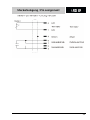
Steckerbelegung
Pin assignment
Pin
Belegung /
Assignment
Spannung /
Voltage
Max. Strom /
Max. current
1 Außenelektrode (u2) < 1.3V < 0.5mA
2 Innenelektrode (u1) < 1.3V < 0.5mA
3 Innenelektrode (i1) < 1.3V < 0.5mA
4 Schirm – – – – – –
5 NTC < 4.5V < 0.5mA
6 Außenelektrode (i2) < 1.3V < 0.5mA
7 NTC < 4.5V < 0.5mA
Alle Spannungen müssen Schutzklein- bzw. berührungsungefährliche
Sicherheitskleinspannungen gemäß IEC 1010 bzw. UL3101 sein.
Alle Ströme zum Sensor dürfen auch im Kurzschlußfall 8 A nicht
überschreiten.
All voltages must be protective low voltages or safety low voltages that
are not shock-hazardous according to IEC 1010 or UL 3101.
All currents to the probe must not exceed 8 A even in case of a short-
circuit!

Technische Daten / Technical data
13
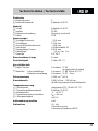
Elektroden
•
Elektrodenzahl
•
Elektrodenmaterial
2
Edelstahl 1.4571
Material
•
Schaft
•
Isolator
•
Kabelverschraubung
•
Kabel
Edelstahl 1.4571
PEEK
Messing, vernickelt
PUR
Abmessungen
•
Schaftdurchmesser
•
Schaftlänge
•
Anschlußkopfdurchmesser
•
Sechskant
•
Gesamtlänge Sensor
•
Kabellänge
•
Gewinde
12,0 mm
113,4 mm
24,8 mm
Schlüsselweite 22
180,0 mm
1,5 m, 3 m, 7 m
1/2“ NPT
Einschraubbare Länge
61 mm
Druckfestigkeit 14 bar (20 °C)
Anschlußtechnik
•
Kabel, Stecker
•
Meßzelle: - Einschraublänge
- Kabelverschraubung
Schutzart IP 65
im gesteckten Zustand
Schutzart IP 68 14 bar (20 °C)
Schutzart IP 67 2 bar
Zellenkonstante 0,100 cm
-1
± 2 %
Einsatzbereich 0,001 µS/cm .. 200 µS/cm
(Auflösung entsprechend Meßgerät)
Temperaturmessung
•
Thermistorart
•
Thermistorgehäusematerial
•
Arbeitsbereich
•
Thermistoransprechverhalten
•
Fühlergenauigkeit
Integrierter NTC (30 k
Ω / 25 °C)
Edelstahl 1.4571
-5 .. +130 °C
t
99
< 20 sec.
± 0,2 K
Aufbewahrungsmedium Luft
Prüfzeichen UL, cUL
Listed Accessory
Laboratory Equipment 8F93

Technische Daten / Technical data
14
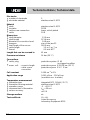
Electrodes
•
number of electrodes
•
electrode material
2
stainless steel 1.4571
Material
•
shaft
•
insulator
•
cable screw connection
•
cable
stainless steel 1.4571
PEEK
brass, nickel-plated
PUR
Dimensions
•
shaft diameter
•
shaft length
•
diameter of connection head
•
hexagon
•
total length of the sensor
•
cable length
•
thread
12.0 mm
113.4 mm
24.8 mm
size of the jaw 22
180.0 mm
1.5 m, 3 m, 7 m
0.5 inch NPT
Length that can be screwed in
61 mm
Pressure resistance 14 bar (20 °C)
Connections
•
cable, plug
•
meas. cell: - screw-in length
- cable screw
connection
protection system IP 65
in plugged condition
protection sysem IP 68 14 bar (20 °C)
protection sysem IP 67 2 bar
Cell constant 0.100 cm
-1
± 2 %
Application range 0.001 µS/cm .. 200 µS/cm
(resolution acc. to meter)
Temperature measurement
•
thermistor type
•
thermistor housing material
•
operation range
•
response time of thermistor
•
sensor accuracy
integrated NTC (30 k
Ω / 25 °C)
stainless steel 1.4571
-5 .. +130 °C
t
99
< 20 sec.
± 0.2 K
Storage medium air
Test certificate UL, cUL
Listed Accessory
Laboratory Equipment 8F93

Betrieb / Wartung
Operation / Maintenance
15
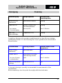
Reinigung Cleaning
Verunreinigung Reinigungsmittel Einwirkzeit bei
Raumtemperatur
Wasserlösliche
Substanzen
entionisiertes Wasser beliebig
Fette und Öle Warmes Wasser und
Haushaltsspülmittel
beliebig
bei starker
Verunreinigung
Brennspiritus max. 5 Minuten
Kalk- und
Hydroxidbeläge
Essigsäure (10 %) beliebig
Gründliches Reinigen ist besonders empfehlenswert vor dem Messen niedriger
Leitfähigkeits-Werten. Vor der Messung den Sensor gründlich mit entionisiertem
Wasser spülen.
Contamination Cleaning solution Reaction time at room
temperature
Water-soluble
substances
Deionized water any
Grease and oil
Warm water and house-
hold cleaning solution
any
in case of heavy
contamination
Spirit max. 5 minutes
Lime and hydroxide
coatings
Acetic acid (10 %) any
A thorough cleaning is specially recommended for measurements of low
conductivities.
Before measuring rinse the probe thoroughly with deionized water.

Garantieerklärung
Warranty
16
Alterung Aging
In der Regel altert die
Leitfähigkeitsmeßzelle nicht. Spezielle
Meßmedien (z. B. starke Säuren und
Laugen, organische Lösungsmittel) oder
zu hohe Temperaturen verkürzen jedoch
erheblich die Lebensdauer bzw. führen zu
Beschädigungen. Für durch derartige
Meßmedien verursachte Ausfälle und bei
mechanischen Beschädigungen besteht
kein Garantieanspruch.
Fundamentally, the conductivity
measuring cell does not age. The cell life
is considerably shortened or the cell
damaged by excessive temperatures or
special measuring solutions (e.g. strong
acid and lye solutions, organic solvents).
The warranty does not cover defects
caused by the measuring medium and
mechanical damage.
Entsorgung Disposal
Wir empfehlen die Entsorgung als
Elektronikschrott.
We recommend disposal as electronic
waste.

Zubehör
Accessories
17
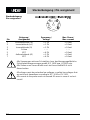
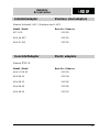
Edelstahladapter Stainless steel adapters
Material: Edelstahl 1.4571 / Stainless steel 1.4571
Modell / Model Best.-Nr. / Order no.
EST-LRD 303 209
ADA-3/4 NPT 303 201
ADA-G1 Zoll 303 202
Kunststoffadapter Plastic adapters
Material: PVC-U
Modell / Model Best.-Nr. / Order no.
ADA-LF-DN 20 303 203
ADA-DN 25 303 204
ADA-DN 32 303 205
ADA-DN 40 303 206
ADA-DN 50 303 207

Garantieerklärung
Warranty
18
Wir übernehmen für die bezeichnete
Meßzelle eine Garantie von 12 Monaten
ab Kaufdatum.
Die Garantie für die Meßzelle erstreckt
sich auf Fabrikationsfehler, die sich
innerhalb der Garantiefrist herausstellen.
Der Garantieanspruch erstreckt sich auf
die Wiederherstellung der
Funktionsbereitschaft, nicht jedoch auf
die Geltendmachung weitergehender
Schadenersatzansprüche. Bei
unsachgemäßer Behandlung oder bei
unzulässiger Öffnung der Meßzelle
erlischt der Garantieanspruch.
Zur Feststellung der Garantiepflicht die
Meßzelle und den Kaufbeleg mit
Kaufdatum frachtfrei bzw. postfrei
einsenden.
The designated measuring cell is covered
by a warranty of 12 months from the date
of purchase.
The measuring cell warranty extends to
manufacturing faults that are determined
within the period of warranty.
The warranty claim extends to restoring
the measuring cell to readiness for use
but not, however, to any further claims for
damages. Improper handling or
unauthorized opening of the measuring
cell invalidates any warranty claim.
To ascertain the warranty liability, return
the measuring cell and proof of purchase
together with the date of purchase freight
paid or prepaid.
-
 1
1
-
 2
2
-
 3
3
-
 4
4
-
 5
5
-
 6
6
-
 7
7
-
 8
8
-
 9
9
-
 10
10
-
 11
11
-
 12
12
-
 13
13
-
 14
14
-
 15
15
-
 16
16
-
 17
17
-
 18
18


in anderen Sprachen
- English: wtw LRD 01 User manual
Verwandte Papiere
Sonstige Unterlagen
-
ProMinent DULCOTEST Assembly And Operating Instructions Manual
-
SICK LFP Inox mit WHG-Zulassung TDR-Füllstandsensor Bedienungsanleitung
-
-
-
Buhler GAS 222.31 Ex2 Installation And Operation Instructions Manual
-
Buhler GAS 222.21 AMEX Installation And Operation Instructions Manual
-
WIKA TC12-A tag:model:TC12-B tag:model:TC12-M tag:model:TR12-A tag:model:TR12-B tag:model:TR12-M Bedienungsanleitung
-
-
-