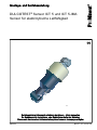
ProMinent DULCOTEST Assembly And Operating Instructions Manual
- Typ
- Assembly And Operating Instructions Manual

DULCOTEST
®
sensor ICT 5 and ICT 5-IMA
Sensor for electrical conductivity
Assembly and operating instructions
A2632
EN/DE
982358 BA DT 157 10/18 DE/EN
Please carefully read these operating instructions before use. · Do not discard.
The operator shall be liable for any damage caused by installation or operating errors.
The latest version of the operating instructions are available on our homepage.

Overall Table of Con‐
tents
EN
DULCOTEST
®
sensor ICT 5 and ICT
5-IMA Sensor for electrical conduc‐
tivity..................................................... 4
1 Introduction.................................... 8
1.1 Measuring principle.................... 8
1.2 Construction and function of
the sensor................................... 9
1.3 Nameplate................................ 12
1.4 Scope of delivery...................... 12
2 Safety and responsibility............. 13
2.1 Labelling of Warning Informa‐
tion............................................ 13
2.2 User qualification...................... 15
2.3 General safety information....... 16
2.4 Intended use............................. 17
2.5 Information in the event of an
emergency................................ 17
3 How to store and transport the
sensor.......................................... 18
3.1 Storage..................................... 18
3.2 Transport.................................. 18
4 Assembly and installation............ 19
4.1 Installation of sensor type ICT
5............................................... 20
4.2 Installation of sensor type ICT
5-IMA........................................ 23
4.3 Electrical installation................. 24
5 Maintenance................................ 26
6 Rectifying faults and malfunc‐
tions............................................. 27
7 Disposal of used parts................. 28
8 Accessories................................. 29
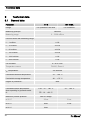
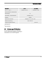
9 Technical data............................. 30
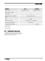
9.1 General data............................. 30
9.2 Certification/Test marks............ 31
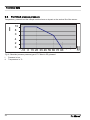
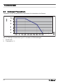
9.3 Permitted process pressure..... 32
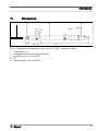
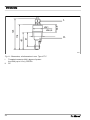
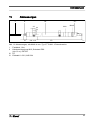
10 Dimensions................................ 33
DE
DULCOTEST
®
Sensor ICT 5 und
ICT 5-IMA Sensor für elektrolytische
Leitfähigkeit....................................... 36
1 Einleitung..................................... 40
1.1 Messprinzip.............................. 40
1.2 Aufbau und Funktion des Sen‐
sors........................................... 41
1.3 Typenschild.............................. 44
1.4 Lieferumfang............................ 44
2 Sicherheit und Verantwortung..... 45
2.1 Kennzeichnung der Warnhin‐
weise........................................ 45
2.2 Benutzer-Qualifikation.............. 47
2.3 Allgemeine Sicherheitshin‐
weise........................................ 48
2.4 Bestimmungsgemäße Verwen‐
dung......................................... 49
2.5 Angaben für den Notfall............ 49
3 So lagern und transportieren Sie
den Sensor.................................. 50
3.1 Lagerung.................................. 50
3.2 Transport.................................. 50
4 Montage und Installation............. 51
4.1 Montage des Sensortyps ICT
5............................................... 52
4.2 Montage des Sensortyps ICT
5-IMA........................................ 55
4.3 Elektrische Installation.............. 56
5 Wartung....................................... 58
6 Fehler und Störungen beheben... 59
7 Altteileentsorgung........................ 60
8 Zubehör....................................... 61
9 Technische Daten....................... 62
9.1 Allgemeine Daten..................... 62
9.2 Zulassungen/Prüfzeichen......... 63
9.3 Zulässiger Prozessdruck.......... 64
Overall Table of Contents
2


DULCOTEST
®
sensor ICT 5 and ICT 5-IMA
Sensor for electrical conductivity
Assembly and operating instructions
A2632
EN
982358 BA DT 157 10/18 DE/EN
Please carefully read these operating instructions before use. · Do not discard.
The operator shall be liable for any damage caused by installation or operating errors.
The latest version of the operating instructions are available on our homepage.

General non-discriminatory approach In order to make it easier to read, this docu‐
ment uses the male form in grammatical struc‐
tures but with an implied neutral sense. It is
aimed equally at both men and women. We
kindly ask female readers for their under‐
standing in this simplification of the text.
Supplementary information
Please read the supplementary information in its entirety.
Information
This provides important information relating to the correct operation of the unit or is intended
to make your work easier.
Warning information
Warning information includes detailed descriptions of the hazardous situation, see
Ä Chapter 2.1
‘Labelling of Warning Information’ on page 13
.
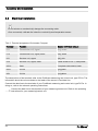
The following symbols are used to highlight instructions, links, lists, results and other elements in
this document:
Tab. 1: More symbols
Symbol Description
Action, step by step.
⇨ Outcome of an action.
Links to elements or sections of these instructions or other applicable docu‐
ments.
n
List without set order.
[Button]
Display element (e.g. indicators).
Operating element (e.g. button, switch).
Supplemental directives
5

Symbol Description
‘Display /GUI’
Screen elements (e.g. buttons, assignment of function keys).
CODE
Presentation of software elements and/or texts.
Supplemental directives
6

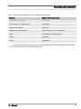
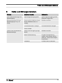
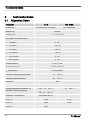
Table of contents
1 Introduction............................................................................................................................. 8
1.1 Measuring principle........................................................................................................ 8
1.2 Construction and function of the sensor......................................................................... 9
1.3 Nameplate.................................................................................................................... 12
1.4 Scope of delivery.......................................................................................................... 12
2 Safety and responsibility....................................................................................................... 13
2.1 Labelling of Warning Information.................................................................................. 13
2.2 User qualification.......................................................................................................... 15
2.3 General safety information........................................................................................... 16
2.4 Intended use................................................................................................................. 17
2.5 Information in the event of an emergency.................................................................... 17
3 How to store and transport the sensor.................................................................................. 18
3.1 Storage......................................................................................................................... 18
3.2 Transport...................................................................................................................... 18
4 Assembly and installation...................................................................................................... 19
4.1 Installation of sensor type ICT 5................................................................................... 20
4.2 Installation of sensor type ICT 5-IMA........................................................................... 23
4.3 Electrical installation..................................................................................................... 24
5 Maintenance.......................................................................................................................... 26
6 Rectifying faults and malfunctions......................................................................................... 27
7 Disposal of used parts........................................................................................................... 28
8 Accessories........................................................................................................................... 29
9 Technical data....................................................................................................................... 30
9.1 General data................................................................................................................. 30
9.2 Certification/Test marks................................................................................................ 31
9.3 Permitted process pressure......................................................................................... 32
10 Dimensions........................................................................................................................... 33
Table of contents
7

1 Introduction
These operating instructions provide informa‐
tion on the technical data and functions of the
DULCOTEST
®
sensor for inductive conduc‐
tivity, ICT 5 and ICT-IMA.
Sensor type ICT 5 is designed for continuous
flow operation.
Sensor type ICT 5-IMA is integrated in an
immersion tube for immersion in a storage tank
and in an open channel.
The sensor records the electrolytic conductivity
of an aqueous process liquid online. Both types
of sensor work on the basis of an inductive
measuring principle. The sensor is almost
maintenance-free due to the inductive meas‐
uring process. Solid deposits and fatty or oily
films on the surface of the sensor have no
impact on its measuring precision. The sensor
is particularly suitable for measuring high con‐
ductivities of up to 2000 mS/cm. A stand-alone
temperature sensor (Pt1000) with a short
response time records the process tempera‐
ture. The temperature sensor is enclosed within
a protective stainless steel sleeve. Tempera‐
ture correction of the conductivity measurement
in the connected controller is provided for by
the temperature sensor (Pt1000).
Typical applications
The sensor is predominantly designed for appli‐
cations in water treatment and for water moni‐
toring, e.g.:
n Contaminated waste water and process
water
n Air conditioning plants and chillers
n Blowdown control in cooling towers,
n Flushing baths,
n Vehicle washing systems,
n Salt water desalination (feed),
n Swimming pool water control.
You can also use both types of sensor in conta‐
minated water or in aggressive media, which is
chemically inert to PVC/EPDM and/or PP/
EPDM (depending on the design of the sensor).
1.1 Measuring principle
The electrolytic conductivity is measured with
an inductive sensor. The sensor contains a
transmission and receiver coil. Sine alternating
voltage feeds the transmission coil. A sample
flow is induced into the receiver coil depending
on the conductivity of the liquid to be meas‐
ured. The sample flow is proportional to the
conductivity of the medium.
Introduction
8

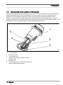
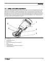
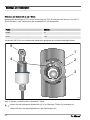
1.2 Construction and function of the sensor
The inductive transducer of the two types of sensor ICT 5 and ICT 5-IMA consists of a hermetically
sealed polypropylene (PP) body. A transmission coil and a receiver coil are incorporated in the
transducer. A flow opening in the sensor (sensor eye) permits the measuring medium to flow
through. There is galvanic isolation between the sample medium and the signal output. A stand-
alone temperature sensor (Pt1000) with a short response time records the process temperature. The
temperature sensor is enclosed within a protective stainless steel sleeve.
A2617
4
3
2
1
5
Fig. 1: Components
1 PP sensor body
2 Transmission coil
3 Sensor eye through which the sample
medium flows
4 Receiver coil
5 Temperature sensor, stand-alone, enclosed
within a stainless steel sleeve
Introduction
9

Sensor type ICT 5
The sensor type ICT5 is connected to a standard DN40 T-piece (on site) using a threaded socket
and a union nut for operation in the flow.
A2641
Fig. 2: Sensor type ICT 5
1. Threaded socket, G 1 1/2” (PVC or PP)
2. Union nut (PVC or PP)
Introduction
10

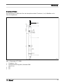
Sensor type ICT5-IMA
The sensor type ICT5-IMA is immersed by the fully assembled immersion tube (1 m) in the storage
tank and channel.
A2642
Fig. 3: Sensor type ICT 5-IMA
1. Fixed cable, 10 m
2. Threaded connector M16, degree of protec‐
tion, IP68 (up to 0.2 m)
3. PP
4. PP
Introduction
11

1.3 Nameplate
The cell constant K is needed for calibration on the transmitter/controller.
A2637
Fig. 4: ICT5 nameplate
A2638
Fig. 5: ICT5-IMA nameplate
1.4 Scope of delivery
Scope of delivery of sensor type ICT 5:
n Sensor type ICT 5, order number 1095248
n Straight solvent union PVC for adaptation
of the sensor to a standard T-piece DN40,
PVC (T-piece not included in the scope of
delivery)
n Assembly and operating instructions
Scope of delivery of sensor type ICT 5-IMA:
n Sensor type ICT 5-IMA, order number
1095249
n Assembly and operating instructions
Introduction
12

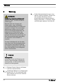
2 Safety and responsibility
2.1 Labelling of Warning Infor‐
mation
Introduction
These operating instructions provide informa‐
tion on the technical data and functions of the
product. These operating instructions provide
detailed warning information and are provided
as clear step-by-step instructions.
The warning information and notes are categor‐
ised according to the following scheme. A
number of different symbols are used to denote
different situations. The symbols shown here
serve only as examples.
DANGER!
Nature and source of the danger
Consequence: Fatal or very serious
injuries.
Measure to be taken to avoid this
danger.
Description of hazard
– Denotes an immediate threatening
danger. If the situation is disre‐
garded, it will result in fatal or very
serious injuries.
WARNING!
Nature and source of the danger
Possible consequence: Fatal or very
serious injuries.
Measure to be taken to avoid this
danger.
– Denotes a possibly hazardous sit‐
uation. If the situation is disre‐
garded, it could result in fatal or
very serious injuries.
CAUTION!
Nature and source of the danger
Possible consequence: Slight or minor
injuries. Material damage.
Measure to be taken to avoid this
danger.
– Denotes a possibly hazardous sit‐
uation. If the situation is disre‐
garded, it could result in slight or
minor injuries. May also be used
as a warning about material
damage.
Safety and responsibility
13

NOTICE!
Nature and source of the danger
Damage to the product or its surround‐
ings.
Measure to be taken to avoid this
danger.
– Denotes a possibly damaging sit‐
uation. If the situation is disre‐
garded, the product or an object in
its vicinity could be damaged.
Type of information
Hints on use and additional information.
Source of the information. Additional
measures.
–
Denotes hints on use and other
useful information. It does not indi‐
cate a hazardous or damaging sit‐
uation.
Safety and responsibility
14

2.2 User qualification
WARNING!
Danger of injury with inadequately qualified personnel
The operator of the system / equipment is responsible for ensuring that the qualifications are
fulfilled.
If inadequately qualified personnel work on the unit or loiter in the hazard zone of the unit,
this could result in dangers that could cause serious injuries and material damage.
– All work on the unit should therefore only be conducted by qualified personnel.
– Unqualified personnel should be kept away from the hazard zone.
The pertinent accident prevention regulations, as well as all other generally acknowledged
safety regulations, must be adhered to.
Training Definition
Instructed personnel An instructed person is deemed to be a person who has been
instructed and, if required, trained in the tasks assigned to him and pos‐
sible dangers that could result from improper behaviour, as well as
having been instructed in the required protective equipment and protec‐
tive measures.
Trained user A trained user is a person who fulfils the requirements made of an
instructed person and who has also received additional training specific
to the system from the manufacturer or another authorised distribution
partner.
Trained, qualified per‐
sonnel
A trained, qualified employee is deemed to be a person who is able to
assess the tasks assigned to him and recognize possible hazards
based on his training, knowledge and experience, as well as knowledge
of pertinent regulations. A trained, qualified employee must be able to
perform the tasks assigned to him independently with the assistance of
drawing documentation and parts lists. The assessment of a person's
technical training can also be based on several years of work in the rel‐
evant field.
Safety and responsibility
15

Training Definition
Electrical technician An electrical technician is able to complete work on electrical systems
and recognise and avoid possible dangers independently based on his
technical training and experience as well as knowledge of pertinent
standards and regulations. An electrical technician must be able to per‐
form the tasks assigned to him independently with the assistance of
drawing documentation, parts lists, terminal and circuit diagrams. The
electrical technician must be specifically trained for the working environ‐
ment in which the electrical technician is employed and be conversant
with the relevant standards and regulations.
Service The Service department refers to service technicians, who have
received proven training and have been authorised by the manufacturer
to work on the system.
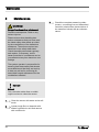
2.3 General safety information
WARNING!
Unauthorised access!
Possible consequence: Fatal or very
serious injuries
– Measure: Ensure that there can be
no unauthorised access to the
device
– Only trained personnel may fit,
install, service and operate this
sensor
CAUTION!
Functional limitations
Possible consequence: Slight or minor
injuries. Material damage
– Check the sensor regularly for dirt
and contamination
– Observe all applicable national
regulations relating to mainte‐
nance, service and calibration
intervals
Safety and responsibility
16

2.4 Intended use
n Only use the sensor to measure and regu‐
late electrolytic conductivity in aqueous
media, which are used in the applications
described in these operating instructions.
n All other uses or modifications are pro‐
hibited.
n The sensor is not a safety component in
the sense of DIN EN ISO
13849-1:2008-12. If there is a critical
process in your measurement and control
circuit, then it is your responsibility to make
sure this process is safe.
2.5 Information in the event of
an emergency
n In the event of an emergency, switch off
the controller
n If liquid escapes from the continuous flow
gauge, close the stopcocks on the inlet
and outlet installed by the customer
n Observe the plant operator's safety infor‐
mation before opening the continuous flow
gauge
Safety and responsibility
17

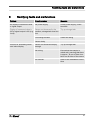
3 How to store and transport the sensor
Original packaging
User qualification: instructed user, see
Ä Chapter 2.2 ‘User qualification’ on page 15
Damage to the product.
n Only transport, ship and store the sensor
in its original packaging.
n Retain the packaging in its entirety
including the polystyrene inserts.
3.1 Storage
Storage and transport temperature:
n complete sensor -20 °C ... 75 °C.
Humidity: maximum 90 % relative air humidity,
non-condensing.
Other: No dust, no direct sunlight.
3.2 Transport
The sensor should be transported in its original
packaging and in compliance with the permis‐
sible environmental conditions. No further spe‐
cial conditions have to be observed in relation
to transport.
How to store and transport the sensor
18

4 Assembly and installation
n User qualification, mechanical installation:
trained and qualified personnel
Ä Chapter
2.2 ‘User qualification’ on page 15
n User qualification, electrical installation:
electrical technician
Ä Chapter 2.2 ‘User
qualification’ on page 15
WARNING!
Danger from hazardous substances!
Possible consequence: Fatal or very
serious injuries.
Please ensure when handling haz‐
ardous substances that you have read
the latest safety data sheets provided
by the manufacture of the hazardous
substance. The actions required are
described in the safety data sheet.
Check the safety data sheet regularly
and replace, if necessary, as the
hazard potential of a substance can be
re-evaluated at any time based on new
findings.
The system operator is responsible for
ensuring that these safety data sheets
are available and that they are kept up
to date, as well as for producing an
associated hazard assessment for the
workstations affected.
Installation site
Ensure that there is unimpeded access for sub‐
sequent calibration.
The mounting must be secure and low-vibra‐
tion.
Avoid direct sunlight.
Make sure that the medium flows correctly
through and around the sensor.
Maintain a minimum distance of 20 mm from
the sensor to the tube wall when installing in
pipework.
Minimum compensation will be achieved with
the “Installation factor” parameter if you cannot
adhere to these minimum spacings.
Provide a representative installation site for typ‐
ical conductivity and/or concentration when
immersing in a tank.
Assembly and installation
19

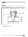
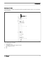
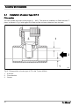
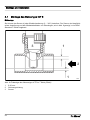
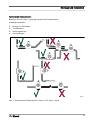
4.1 Installation of sensor type ICT 5
Fitting position
You can operate the sensor at any angle (0 ... 360°). The sensor is installed in a DN40 standard T-
piece, as shown in Fig. 6 with regard to its flow and the minimum distances from the walls.
1
1
3
2
A2618
Fig. 6: Fitting position of sensor type ICT5 in the T-piece (DN40)
1 ≧ 20 mm
2 Flow direction
3 Sensor
Assembly and installation
20
Seite wird geladen ...
Seite wird geladen ...
Seite wird geladen ...
Seite wird geladen ...
Seite wird geladen ...
Seite wird geladen ...
Seite wird geladen ...
Seite wird geladen ...
Seite wird geladen ...
Seite wird geladen ...
Seite wird geladen ...
Seite wird geladen ...
Seite wird geladen ...
Seite wird geladen ...
Seite wird geladen ...
Seite wird geladen ...
Seite wird geladen ...
Seite wird geladen ...
Seite wird geladen ...
Seite wird geladen ...
Seite wird geladen ...
Seite wird geladen ...
Seite wird geladen ...
Seite wird geladen ...
Seite wird geladen ...
Seite wird geladen ...
Seite wird geladen ...
Seite wird geladen ...
Seite wird geladen ...
Seite wird geladen ...
Seite wird geladen ...
Seite wird geladen ...
Seite wird geladen ...
Seite wird geladen ...
Seite wird geladen ...
Seite wird geladen ...
Seite wird geladen ...
Seite wird geladen ...
Seite wird geladen ...
Seite wird geladen ...
Seite wird geladen ...
Seite wird geladen ...
Seite wird geladen ...
Seite wird geladen ...
Seite wird geladen ...
Seite wird geladen ...
Seite wird geladen ...
Seite wird geladen ...
-
 1
1
-
 2
2
-
 3
3
-
 4
4
-
 5
5
-
 6
6
-
 7
7
-
 8
8
-
 9
9
-
 10
10
-
 11
11
-
 12
12
-
 13
13
-
 14
14
-
 15
15
-
 16
16
-
 17
17
-
 18
18
-
 19
19
-
 20
20
-
 21
21
-
 22
22
-
 23
23
-
 24
24
-
 25
25
-
 26
26
-
 27
27
-
 28
28
-
 29
29
-
 30
30
-
 31
31
-
 32
32
-
 33
33
-
 34
34
-
 35
35
-
 36
36
-
 37
37
-
 38
38
-
 39
39
-
 40
40
-
 41
41
-
 42
42
-
 43
43
-
 44
44
-
 45
45
-
 46
46
-
 47
47
-
 48
48
-
 49
49
-
 50
50
-
 51
51
-
 52
52
-
 53
53
-
 54
54
-
 55
55
-
 56
56
-
 57
57
-
 58
58
-
 59
59
-
 60
60
-
 61
61
-
 62
62
-
 63
63
-
 64
64
-
 65
65
-
 66
66
-
 67
67
-
 68
68


ProMinent DULCOTEST Assembly And Operating Instructions Manual
- Typ
- Assembly And Operating Instructions Manual
in anderen Sprachen
- English: ProMinent DULCOTEST
Verwandte Artikel
-
ProMinent DULCOTEST ICT 2 Assembly And Operating Instructions Manual
-
-
-
-
-