POLYTRON SPM-PSTI/PTTI DVB-S/DVB-T in AV twin module Bedienungsanleitung
- Typ
- Bedienungsanleitung

1
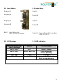
QPSK-PAL-Module / modules
SPM-PSTI
SPM-PTTI
Bedienungsanleitung/
Operating manual
0901333 V2.0

2
ACHTUNG Vor dem Arbeiten am Grund-
gerät bitte unbedingt die Sicherheitsbe-
stimmungen des Grundgeräts sorgfältig lesen!
ACHTUNG Diese Baugruppe ent-
hält ESD-Bauteile!
ESD-Schutzmaßnahmen beachten!
HINWEIS
Der Inhalt dieses Firmenhandbuches ist urhe-
berrechtlich geschützt und darf ohne Geneh-
migung des Erstellers weder ganz noch teil-
weise in irgendeiner Form vervielfältigt oder
kopiert werden. Änderungen in diesem Fir-
menhandbuch, die ohne Zustimmung des
Erstellers erfolgen, können zum Verlust der
Gewährleistung bzw. zur Ablehnung der Pro-
dukthaftung seitens des Herstellers führen. Für
Verbesserungsvorschläge ist der Ersteller
dankbar.
Ersteller:
Polytron-Vertrieb GmbH
Postfach 10 02 33
75313 Bad Wildbad
Germany
Unten stehende Hervorhebungen werden in
diesem Handbuch mit folgenden Bedeutungen
verwendet:
HINWEIS gilt für technische Erfordernis-
se, die der Benutzer der Gerä-
te besonders beachten muss,
um eine einwandfreie Funktion
der Geräte/Anlage zu gewähr-
leisten.
ACHTUNG bezieht sich auf Anweisungen,
die genau einzuhalten sind,
um eine Beschädigung oder
Zerstörung des Gerätes zu
vermeiden.
VORSICHT steht für Anweisungen, deren
Nichtbeachtung eine Gefähr-
dung von Personen nicht aus-
schließt.
Bei Hinweisen auf ein durch eine Ortszahl ver-
sehenes Bauteil z.B. (Bild 1/3) bezieht sich in
diesem Beispiel der Hinweis auf Bild 1 Orts-
zahl 3.
ATTENTION Before working on the basie-
unit please read the safety precautions of the
base unit carefully!
ATTENTION This unit is equipped
with ESD-components!
Take protective measures against static
discharge!
NOTE
The contents of this company manual are
copyrighted and must not be duplicated or cop-
ied in any form, either partially or in full, without
the prior consent of the creator. Changes in
this company manual which are carried out
without consent of the creator can lead to the
loss of the guarantee or to the rejection of the
product liability on the part of the manufacturer.
The creator is grateful for suggestions for im-
provement.
Creator:
Polytron-Vertrieb GmbH
Postfach 10 02 33
75313 Bad Wildbad
Germany
The following emphases are used in this man-
ual with the following meanings:
NOTE apply to technical require-
ments which the user of the
equipment must particularly
take into account to ensure
a faultless function of the
equipment/plant.
ATTENTION refers to instructions which
have to be adhered exactly
to avoid damage or destruc-
tion of the device.
CAUTION stand for instructions whose
nonobservance doesn't ex-
clude endangering of per-
sons.
At references to a component e.g. (figure 1/3)
provided by a place number the reference to
picture 1 place number 3 refers in this exam-
ple.

3
1 Beschreibung
Die Module SPM-PSTI/PTTI sind
Twin-DVB-S / DVB-T Empfangsmo-
dule zur Umsetzung von zwei von
einander unabhängigen
QPSK/COFDM modulierten Pro-
grammen in AV-Signale. Das AV-
Signal wird anschließend von einem
Modulator aus der SPM-Serie, der
über eine Sub-D-Steckverbindung mit
dem eingesetzten Digitalmodul ver-
bunden wird, in einen TV-Kanal ge-
wandelt.
Zwei unabhängige Tuner erlauben
den Empfang von zwei Programmen
von unterschiedlichen Transpondern.
Werden 2 Programme vom gleichen
Transponder empfangen kann der
Tuner B als Slave programmiert und
damit abgeschaltet werden (niedriger
Energieverbrauch).
Der Common Interface Steckplatz
ermöglicht das Einstecken eines Kar-
tenlesers für das entsprechende Ent-
schlüsselungssystem einer Smart-
Card.
Abhängig von dem CAM-Modul und
der Smartkarte können 2 Programme
gleichzeitig entschlüsselt werden.
1 Description
The modules SPM-PSTI/SPM-PTTI
are DVB-S / DVB-T reception mod-
ules for the conversion of QPSK /
COFDM modulated programs into AV
signals. Afterwards the AV signal is
converted into a TV channel by a
modulator from the SPM series. The
modulator is connected with the used
digital module by a Sub-D connec-
tion.
Two independent tuners support the
the conversion of two TV channels of
two different MPEG2 data streams.
IF two TV channels from one data
stream should be received, the tuner
B can be programme as slave and
can be deactivated (lower power
consumption).
The Common interface slot enables
to plug in a card reader for the corre-
sponding deciphering system of a
Smart card.
Depending on the CAM and the
smart card, it´s possible to decode
two programs simultaneousley.

4
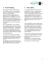
2 Inbetriebnahme
Die Bestückung des Grundgerätes
erfolgt in Abwechslung zwischen ei-
nem SPM-Modul und einem Modula-
tor, d.h.
Steckplatz 1: Twin-Modulator
Steckplatz 2: SPM-PSTI-Modul
Steckplatz 3: Twin-Modulator
Steckplatz 4: SPM-PTTI-Modul usw.
Die Module müssen mit den jeweili-
gen Sub-D-Verbindungskabel mitein-
ander verbunden werden. (Bild 2)
2 Putting into operation
The assembly of the base unit takes
place in alternation between a SPM
module and a modulator, i.e.
Module slot 1: Twin modulator
Module slot 2: SPM-PSTI module
Module slot 3: Modulator
Module slot 4: SPM-PTTI module
etc.
The modules will be connected with
each other by the Sub-D connecting
cables. (Figure 2)
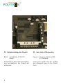
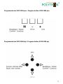
Bild 2 Module im SPM 1000
Figure 2 Modules in the SPM 1000

5
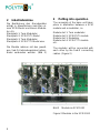
2.1 Anschlüsse
Eingang A
Ausgang A
Eingang B
Ausgang B
Bild 3 Anschlüsse am
SPM-PSTI/PTTI-Modul
2.2 LED Anzeige
2.1Connections
Input A
Output A
Input B
Output B
Figure 3 Connections of the module
SPM-PSTI/PTTI
2.2 LED Indication
LNB/5 V Spannung/
LNB/5 Voltage
Signal LED-Anzeige
AUS / OFF OK Grün / Green
AUS / OFF Nicht / NOT OK Grün blinkend /
Green blinking
AN / ON OK Orange
AN / ON Nicht / NOT OK Rot/orange blinkend
Red /Orange blinking

6
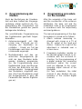
2.3 Kartenaufnahme des Moduls
Bild 5 Schnittstelle SPM-PSTI-
Modul
Kartenleser in das Modul einschieben
und anschließend die Smart-Card
einstecken.
2.3 Card slots of the module
Figure 5 Common interface SPM-
PSTI-module
Insert card reader into the module
and afterwards plug in the Smart-
Card.

7
3 Programmierung der
Module
Nach der Bestückung der Grundein-
heit und dem Aufbau der Eingangs-
verteilung erfolgt zunächst die Pro-
grammierung der Grundeinheit und
der Modulatoren gemäß der jeweils
beiliegenden Anleitung.
Die anschließende Programmierung
der Digitalmodule geschieht folgen-
dermaßen:
1. Antennenmessgerät mit Bild-
schirm bzw. TV-Gerät am HF-
Ausgang der Kopfstation an-
schließen – Grund: ein Teil der
Einstellungen wird über ein Bild-
schirmmenü angezeigt.
2. Modulatormodul auf den ge-
wünschten Ausgangskanal, ge-
mäß der dem Modulator beilie-
genden Anleitung programmie-
ren. Zur Programmierung eines
Digitalmoduls muss das Messge-
rät bzw. der Bildschirm auf den
entsprechenden Ausgangskanal
des Modulators eingestellt wer-
den. (Bei Twin-Modulatoren zeigt
der Ausgangskanal A auch die
Parameter des zweiten Digitalzu-
ges an.)
3 Programming procedure
for the modules
After the assembly of the base unit
and the construction of the entrance
distribution, the base unit and the
modulators have to be programmed
in accordance with the respectively
enclosed guidance.
The manual programming of the digi-
tal modules is carried out as follows:
1. Attach antenna measuring in-
strument with screen or a TV at
the RF output of the head end
station – Reason for: a part of the
adjustment is indicated over a
screen menu.
2. Programm modulator module on
the desired output channel, in ac-
cordance with the enclosed in-
struction. For the programming of
a digital module the measuring
instrument and/or the screen
must be adjusted to the corre-
sponding output channel of the
modulator.
(At Twin modulators, the initial
channel A also displays the pa-
rameters of the second digital
channel.)

8
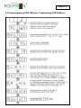
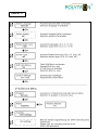
3. Programmierung der Digitalmo-
dule gemäß des auf den folgen-
den Seiten abgebildeten Pro-
grammierablaufs. Hierbei ist zu
beachten, dass der, dem einge-
setzten Grundgerät entsprechen-
de, Programmierablauf gewählt
wird.
Die Anwahl und Bestätigung der
Bedienschritte erfolgt über die
Tastatur unterhalb des Displays.
HINWEIS
Während des Programmiervor-
gangs werden sowohl auf dem
Display der Grundeinheit als auch
auf der Bildschirmanzeige Pro-
grammierungshinweise angezeigt!
Nach einem Steckplatzwechsel
oder dem Übertragen von Daten
mit einem CopyKey, müssen die-
se neu bestätigt werden.
ACHTUNG
Die im Grundgerät benötigte
min. Softwareversion zur fehler-
freien Programmierung der Mo-
dule, ist auf dem Modul ange-
geben.
3. Programm the digital modules in
accordance with the program se-
quence shown on the following
pages. Note, that the program
sequence corresponding to the
assigned base unit is selected.
The selection and confirmation of
the operating steps is carried out
via the keyboard below the dis-
play.
NOTE
During the programming process,
programming references are dis-
played on the base unit and on
the screen display!
After a card location change or
transferring data with a CopyKey,
the data must be confirmed again.
ATTENTION
The min. required software ver-
sion of the base unit for error-
free programming, is specified
on the module.

9
Programmtasten SPM 1000 plus / Program button SPM 1000 plus
Programmtasten SPM 1000 digi / Program button SPM 1000 digi

10
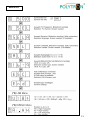
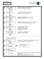
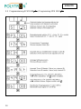
3.1 Programmierung SPM 1000 plus / Programming SPM 1000 plus
SPM-PSTI

11
SPM-PSTI

12
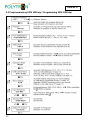
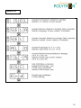
3.2 Programmierung SPM 1000 digi / Programming SPM 1000 digi
SPM-PSTI

13
SPM-PSTI

14
3.3 Programmierung SPM 1000 plus
plusplus
plus / Programming SPM 1000 plus
plusplus
plus
SPM-PTTI

15
SPM-PTTI

16
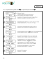
3.4 Programmierung SPM 1000 digi
digidigi
digi / Programming SPM 1000 digi
digidigi
digi
SPM-PTTI

17
SPM-PTTI

18
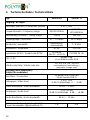
4 Technische Daten / Technical Data
Typ SPM-PSTI SPM-PTTI
Eingang / RF-Input
Anschluss (Buchse) / Connection (socket) 2 x F / 75 Ω
Frequenzbereich / Frequency range 950-2150 MHz
174-230/
470-862 MHz
Abstimmung (Schritte) / Tuning (steps) 1-MHz 250 kHz
Eingangspegel / Input level 47 ... 70 dBµV 50-75 dBµV
Bandbreite / bandwidth
automatisch /
automatically
7 / 8 MHz
Modulation / Modulation QPSK COFDM
Symbolrate QPSK / Symbol rate QPSK
40 MBit/S
(MCPC + SCPC)
COFDM 2k, 8k
FEC / FEC
gemäß DVB
in accordance with DVB
Viterbi code Rate / Viterbi code rate
1/2, 2/3, 3/4, 5/6, 7/8, 8/9
(automatische Umschaltung) /
(automatic change over)
Ausgang (zum Modulator) /
Output (to modulator)
Anschluss / Connection
15-polige SUB-D-Buchse
15-pin female SUB-D
Videopegel / Video level
1 V
pp
/ 75 Ω
(1-dB-Schritte/steps, 0 … -3 dB)
Video-Bandbreite / Video bandwidth 20 Hz … 5 MHz
Audiopegel / Audio level
1 V
pp
/ 10 kΩ
(3-dB-Schritte/steps, -6 dB … +6 dB)
Audio-Bandbreite / Audio bandwidth 40 Hz … 15 kHz
Leistungsaufnahme (typische ohne CI)
Power consumption (typical without CI)
7 W 8 W

19
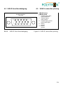
4.1 SUB-D Anschlussbelegung 4.1 SUB-D connection pinning
Bild 6 SUB-D Anschlussbelegung Figure 6 SUB-D connection pinning
SUB
-
D Buchse
SUB-D socket
1 Audioausgang links
audio output left
2 Videoausgang
video output
6 Audioausgang rechts
audio output right
8 Masse
ground
11 Masse
ground
Ansicht von oben
Top view
1
6 10
5
11
15

20
Polytron-Vertrieb GmbH
Postfach 10 02 33
75313 Bad Wildbad
Zentrale/Bestellannahme
H.Q. Order department + 49 (0) 70 81/1702 - 0
Technische Hotline
Technical hotline + 49 (0) 70 81/1702 - 12
Telefax + 49 (0) 70 81) 1702 - 50
Internet http://www.polytron.de
eMail [email protected]
Technische Änderungen vorbehalten
Subject to change without prior notice
Copyright © Polytron-Vertrieb GmbH
-
 1
1
-
 2
2
-
 3
3
-
 4
4
-
 5
5
-
 6
6
-
 7
7
-
 8
8
-
 9
9
-
 10
10
-
 11
11
-
 12
12
-
 13
13
-
 14
14
-
 15
15
-
 16
16
-
 17
17
-
 18
18
-
 19
19
-
 20
20


POLYTRON SPM-PSTI/PTTI DVB-S/DVB-T in AV twin module Bedienungsanleitung
- Typ
- Bedienungsanleitung
in anderen Sprachen
Verwandte Artikel
-
POLYTRON SPM-S2AVT Twin digital DVB-S/S2 in AV Bedienungsanleitung
-
-
-
-
-
-
-
-
-