POLYTRON SPM-PT/PTT DVB-T-PAL module Bedienungsanleitung
- Typ
- Bedienungsanleitung
Seite laden ...

2
ACHTUNG Vor Inbetriebnahme des
Polytron Gerätes bitte unbedingt die Si-
cherheits- und Bedienhinweise lesen!
ACHTUNG Diese Baugruppe ent-
hält ESD-Bauteile!
ESD-Schutzmaßnahmen beachten!
HINWEIS
Der Inhalt dieses Firmenhandbuches ist urhe-
berrechtlich geschützt und darf ohne Geneh-
migung des Erstellers weder ganz noch teil-
weise in irgendeiner Form vervielfältigt oder
kopiert werden. Änderungen in diesem Fir-
menhandbuch, die ohne Zustimmung des
Erstellers erfolgen, können zum Verlust der
Gewährleistung bzw. zur Ablehnung der Pro-
dukthaftung seitens des Herstellers führen. Für
Verbesserungsvorschläge ist der Ersteller
dankbar.
Ersteller:
Polytron-Vertrieb GmbH
Postfach 10 02 33
75313 Bad Wildbad
Germany
Unten stehende Hervorhebungen werden in
diesem Handbuch mit folgenden Bedeutungen
verwendet:
HINWEIS gilt für technische Erfordernis-
se, die der Benutzer der Gerä-
te besonders beachten muss,
um eine einwandfreie Funktion
der Geräte/Anlage zu gewähr-
leisten.
ACHTUNG bezieht sich auf Anweisungen,
die genau einzuhalten sind,
um eine Beschädigung oder
Zerstörung des Gerätes zu
vermeiden.
VORSICHT steht für Anweisungen, deren
Nichtbeachtung eine Gefähr-
dung von Personen nicht aus-
schließt.
Bei Hinweisen auf ein durch eine Ortszahl ver-
sehenes Bauteil z.B. (Bild 1/3) bezieht sich in
diesem Beispiel der Hinweis auf Bild 1 Orts-
zahl 3.
ATTENTION All safety and operation in-
structions should be read before this Poly-
tron product is operated.
ATTENTION This unit is equipped
with ESD-components!
Take protective measures against static
discharge!
NOTE
The contents of this company manual are
copyrighted and must not be duplicated or cop-
ied in any form, either partially or in full, without
the prior consent of the creator. Changes in
this company manual which are carried out
without consent of the creator can lead to the
loss of the guarantee or to the rejection of the
product liability on the part of the manufacturer.
The creator is grateful for suggestions for im-
provement.
Creator:
Polytron-Vertrieb GmbH
Postfach 10 02 33
75313 Bad Wildbad
Germany
The following emphases are used in this man-
ual with the following meanings:
NOTE apply to technical require-
ments which the user of the
equipment must particularly
take into account to ensure
a faultless function of the
equipment/plant.
ATTENTION refers to instructions which
have to be adhered exactly
to avoid damage or destruc-
tion of the device.
CAUTION stand for instructions whose
nonobservance doesn't ex-
clude the endangering of
persons.
At references to a component e.g. (figure 1/3)
provided by a place number the reference to
picture 1 place number 3 refers in this exam-
ple.

3
1 Beschreibung
Bei den Modulen SPM-PT und SPM-
PTT handelt es sich um Empfangs-
module zur Umsetzung von terrestri-
schen, COFDM modulierten Pro-
grammen in AV-Signale. Das AV-
Signal wird anschließend von einem
Modulator aus der SPM-Serie, der
über eine Sub-D-Steckverbindung mit
dem eingesetzten Modul verbunden
wird, in einen TV-Kanal gewandelt.
Das Twinmodul SPM-PTT unterstützt
die simultane Umsetzung von zwei
Programmen.
2 Inbetriebnahme
Die Bestückung des Grundgerätes
erfolgt in Abwechslung zwischen ei-
nem Empfangsmodul und einem Mo-
dulator, d.h.
Steckplatz 1: Modulator
Steckplatz 2: z.B. SPM-PTT-Modul
Steckplatz 3: Modulator
Steckplatz 4: z.B. SPM-PTT-Modul
usw.
Die Module werden durch die beige-
legten Sub-D-Verbindungskabel mit-
einander verbunden. (Bild 1)
1 Description
The modules SPM-PT and SPM-PTT
are receiving modules for the conver-
sion of terrestrial COFDM modulated
programs into AV signals. Afterwards
the AV signal is converted into a TV
channel by a modulator from the
SPM series. The modulator is con-
nected with the inserted digital mod-
ule by a Sub-D connection.
The twin module SPM-PTT supports
the simultaneous conversion of two
channels.
2 Putting into operation
The assembly of the basic equipment
takes place in alternation between a
receiving module and a modulator,
i.e.
Module slot 1: Modulator
Module slot 2: e.g. SPM-PTT module
Module slot 3: Modulator
Module slot 4: e.g. SPM-PTT module
etc.
The modules will be connected with
each other by the enclosed Sub-D in-
terconnecting cables. (Figure 1)

4
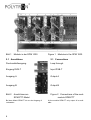
Bild 1 Module in der SPM 1000
2.1 Anschlüsse
Durchschleifausgang
Eingang DVB-T
Ausgang A
Ausgang B
Bild 2 Anschlüsse am
SPM-PTT-Modul
Bei dem Modul SPM-PT ist nur der Ausgang A
vorhanden.
Figure 1 Modules in the SPM 1000
2.1 Connections
Loop through
Input DVB-T
Output A
Output B
Figure 2 Connections of the mod-
module SPM-PTT
At the module SPM-PT only output A is avail-
able.

5
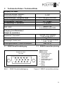
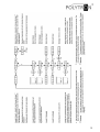
3 Technische Daten / Technical Data
Eingang / RF-Input
Anschluss (Buchse / Stecker) /
Connection (socket / plug)
2 x IEC
Frequenzbereich / Frequency range 174 - 230 / 470 - 862 MHz
Abstimmung (Schritte) / Tuning (steps) 250 kHz
Eingangspegel / Input level 50 - 75 dBµV
ZF-Bandbreite / IF bandwidth 7 / 8 MHz
Modulation / Modulation COFDM 2k, 8k
FEC / FEC
gemäß DVB
in accordance with DVB
Ausgang (zum Modulator) /
Output (to modulator)
Anschluss / Connection
15-polige SUB-D-Buchse
15-pin female SUB-D
Videopegel / Video level 1 V
pp
/ 75 Ω
Audiopegel / Audio level
1 V
pp
/ 10 kΩ (3-dB-Schritte/steps,
-6 dB - +6 dB)
Leistungsaufnahme / Power consumption max. 8,5 W
3.1 SUB-D Anschlussbelegung 3.1 SUB-D connection pinning
Bild 3 SUB-D Anschlussbelegung Figure 3 SUB-D connection pinning
SUB-D Buchse
SUB-D socket
1 Audioausgang links
audio output left
2 Videoausgang
video output
6 Audioausgang rechts
audio output right
8 Masse
ground
11 Masse
ground
Ansicht von oben
Top view
1
6 10
5
11
15

6
4 Programmierung der
Module
Nach der Bestückung der Grundein-
heit und dem Aufbau der Eingangs-
verteilung erfolgt zunächst die Pro-
grammierung der Grundeinheit und
der Modulatoren auf die gewünsch-
ten Ausgangskanäle gemäß der je-
weils beiliegenden Anleitung.
Die anschließende Programmierung
der Digitalmodule geschieht folgen-
dermaßen:
1. Antennenmessgerät mit Bild-
schirm bzw. TV-Gerät am HF-
Ausgang der Kopfstation an-
schließen – ein Teil der Einstel-
lungen wird über ein Bild-
schirmmenü angezeigt.
2. Zur Programmierung eines Digi-
talmoduls muss das Messgerät
auf den entsprechenden Aus-
gangskanal des Modulators, zu-
gehörig zum Kanalzug A des Di-
gitalmoduls, eingestellt werden.
Die Einstellung des Kanals B er-
folgt ebenfalls über den Kanal-
zug A. Nach Bestätigung der Pa-
rameter am Ende der Program-
mierung, wird der Kanalzug B
auf die gewünschten Werte ein-
gestellt.
4 Programming procedure
for the modules
After the assembly of the basic unit
and the construction of the entrance
distribution, the basic unit and the
modulators have to be programmed
on the desired output channels in
accordance with the respectively en-
closed guidance.
The following programming of the
digital modules is carried out as fol-
lows:
1. Attaching antenna measuring in-
strument with screen or a TV at
the RF output of the head end
station – a part of the adjustment
is indicated over a screen menu.
2. For the programming of a digital
module the measuring instru-
ment must be adjusted to the
corresponding output channel of
the modulator, associated to the
channel A of the digital module.
The adjustment of the channel B
is also carried out via the chan-
nel A. After confirmation of the
parameters at the end of the
programming, the channel B has
to be adjusted to the desired
values.

7
3. Programmierung der Digitalmo-
dule gemäß des auf den folgen-
den Seiten abgebildeten Pro-
grammierablaufs. Hierbei ist zu
beachten, dass der, dem einge-
setzten Grundgerät entspre-
chende, Programmierablauf ge-
wählt wird.
Die Anwahl und Bestätigung der
Bedienschritte erfolgt über die
Tastatur unterhalb des Displays.
HINWEIS
¾ Während des Programmiervor-
gangs werden sowohl auf der
Grundeinheit als auch auf der
Bildschirmanzeige Programmie-
rungshinweise angezeigt!
¾ Nach einem Steckplatzwechsel
oder dem Übertragen von Daten
mit einem CopyKey, müssen die
Parameter neu bestätigt werden.
ACHTUNG
¾ Die im Grundgerät benötigte
Softwareversion zur fehlerfrei-
en Programmierung der Modu-
le, ist auf dem Modul angege-
ben und kann der Software-
matrix unter "www.polytron.de
Æ Service Æ Software" ent-
nommen werden.
3. Programming of the digital mo-
dules in accordance with the
program sequence shown on the
following pages. Note, that the
program sequence correspond-
ing to the assigned basic unit is
selected.
The selection and confirmation
of the operating steps is carried
out via the keyboard below the
display.
NOTE
¾ During the programming process,
programming references are dis-
played on the basic unit and on
the screen display!
¾ After a card location change or
transferring data with a CopyKey,
the parameters must be con-
firmed again.
ATTENTION
¾ The required software version
of the basic unit for error-free
programming, is specified on
the module and can be seen in
the software matrix at
"www.polytron.de Æ Service Æ
Software".
Seite laden ...
Seite laden ...

10
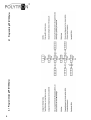
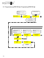
4.2 Programmierung SPM 1000 digi / Programming SPM 1000 digi
→ Program
↨ Service
Polytron Headend
SPM1000 DIGI X.X
←PL01 SPM-PTT→ ↨
PL02 SPM-MSTQ
Modulsteckplatz wählen
choose modul slot
gedrückt halten bis Anzeige
aktiviert ist
keep pressed until display is
activated
Select A,B,ESC:
↨ Channel A →
Select Programm
↨ from OSD →
Select A,B,ESC:
↨ Channel B →
Select A,B,ESC:
↨ Escape →
Confirm Settings
↨ from OSD →
Auswahl des einzustel-
lenden Kanals
Selection of the channel to
be adjusted
Bestätigung
confirmation
Programmauswahl auf dem
Bildschirm
Select a channel (displayed
on screen)
Select Language
↨ from OSD →
Sprachauswahl auf dem
Bildschirm
Select language (displayed
on screen)
Wahl bestätigen,
weiter zum nächsten Punkt
Confirm choice,
forward to the next
p
oint

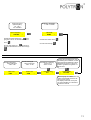
11
Video Level
↨ -3 dB →
Audio Level
↨ -3 dB →
SCREEN TYPE
↨ 4:3 →
Auswahl Videopegel
select video level
-3 dB - 0 dB
Umschaltung / switching
16:9 or 4:3 or
AUTO or OFF
Auswahl Audiopegel
select audio level
-6 dB - +6 dB
Input Frequency
↨ 474 MHz →
Auswahl der Ziffernstelle durch Bewe-
gung des Cursors und Auswahl des Wertes
durch
.
Choose digit position by movement of
the cursor and selection of the value through
.
Eingangsfrequenz
Input Frequency
174 - 230 /
470 - 862 MHz
Bandwidth
↨ 8 MHz →
Bandbreite / bandwidth
7 oder / or 8 MHz
Auswahl des Wertes durch
.
Choose value through
.
Select Subtitle
↨ from OS →
Auswahl der Untertitelsprache oder
Abschaltung des Untertitels, auf dem
angeschlossenen Bildschirm. Dieser
Menüpunkt erscheint nur wenn Un-
tertitel im gewählten Programm vor-
handen sind.
Select language for subtitles, or
switch off the subtitle (the list is dis-
played on the screen).
The display shows this menu point
only when subtitles are contained in
the selected channel.

12
Polytron-Vertrieb GmbH
Postfach 10 02 33
75313 Bad Wildbad
Zentrale/Bestellannahme
H.Q. Order department + 49 (0) 70 81/1702 - 0
Technische Hotline
Technical hotline + 49 (0) 70 81/1702 - 12
Telefax + 49 (0) 70 81) 1702 - 50
Internet http://www.polytron.de
eMail info@polytron.de
Technische Änderungen vorbehalten
Subject to change without prior notice
Copyright © Polytron-Vertrieb GmbH
-
 1
1
-
 2
2
-
 3
3
-
 4
4
-
 5
5
-
 6
6
-
 7
7
-
 8
8
-
 9
9
-
 10
10
-
 11
11
-
 12
12


POLYTRON SPM-PT/PTT DVB-T-PAL module Bedienungsanleitung
- Typ
- Bedienungsanleitung
in anderen Sprachen
Verwandte Papiere
-
POLYTRON SPM-S2AVT Twin digital DVB-S/S2 in AV Bedienungsanleitung
-
-
-
-
-
-
-
-
-

