POLYTRON SPM-FM/TV FM in TV channel modulator Bedienungsanleitung
- Typ
- Bedienungsanleitung

1
UKW-Modul
VHF modul
SPM-FM/TV
Bedienungsanleitung/
Operating manual
0901087 V1.0

2
ACHTUNG Vor dem Arbeiten am Grund-
gerät bitte unbedingt die Sicherheitsbestim-
mungen des Grundgeräts sorgfältig lesen!
ACHTUNG Diese Baugruppe ent-
hält ESD-Bauteile!
ESD-Schutzmaßnahmen beachten!
HINWEIS
Der Inhalt dieses Firmenhandbuches ist urhe-
berrechtlich geschützt und darf ohne Geneh-
migung des Erstellers weder ganz noch teil-
weise in irgendeiner Form vervielfältigt oder
kopiert werden. Änderungen in diesem Fir-
menhandbuch, die ohne Zustimmung des
Erstellers erfolgen, können zum Verlust der
Gewährleistung bzw. zur Ablehnung der Pro-
dukthaftung seitens des Herstellers führen.
Für Verbesserungsvorschläge ist der Ersteller
dankbar.
Ersteller:
Polytron-Vertrieb GmbH
Postfach 10 02 33
75313 Bad Wildbad
Germany
Unten stehende Hervorhebungen werden in
diesem Handbuch mit folgenden Bedeutun-
gen verwendet:
HINWEIS gilt für technische Erforder-
nisse, die der Benutzer der
Geräte besonders beachten
muss, um eine einwandfreie
Funktion der Geräte/Anlage
zu gewährleisten.
ACHTUNG bezieht sich auf Anweisun-
gen, die genau einzuhalten
sind, um eine Beschädigung
oder Zerstörung des Gerätes
zu vermeiden.
VORSICHT steht für Anweisungen, deren
Nichtbeachtung eine Gefähr-
dung von Personen nicht
ausschließt.
Bei Hinweisen auf ein durch eine Ortszahl
versehenes Bauteil z.B. (Bild 1/3) bezieht sich
in diesem Beispiel der Hinweis auf Bild 1
Ortszahl 3.
ATTENTION Before working on the basic
equipment please read the safety precautions
of the basic equipment carefully!
ATTENTION This unit is equipped
with ESD-components!
Take protective measures against static
discharge!
NOTE
The contents of this company manual are
copyrighted and must not be duplicated or
copied in any form, either partially or in full,
without the prior consent of the creator.
Changes in this company manual which are
carried out without consent of the creator can
lead to the loss of the guarantee or to the re-
jection of the product liability on the part of the
manufacturer. The creator is grateful for sug-
gestions for improvement.
Creator:
Polytron-Vertrieb GmbH
Postfach 10 02 33
75313 Bad Wildbad
Germany
The following emphases are used in this man-
ual with the following meanings:
NOTE apply to technical require-
ments which the user of the
equipment must particularly
take into account to ensure
a faultless function of the
equipment/plant.
ATTENTION refers to instructions which
have to be adhered exactly
to avoid damage or de-
struction of the device.
CAUTION stand for instructions
whose nonobservance
doesn't exclude the endan-
gering of persons.
At references to a component e.g. (figure 1/3)
provided by a place number the reference to
picture 1 place number 3 refers in this exam-
ple.

3
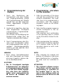
1 Beschreibung
Das Modul SPM-FM/TV wurde spe-
ziell für Hotels konzipiert und ermög-
licht die Verbreitung eines UKW-
Programms über einen Audiokanal
eines Fernsehgerätes.
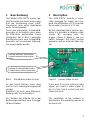
Durch den integrierten Schwarzbild-
generator ist es möglich einen dunk-
len Bildschirm darzustellen. Durch
Umstecken der in Bild 1 gezeigten
Steckbrücke kann vom Schwarzbild-
generator auf ein externes Videosig-
nal umgeschaltet werden.
Bild 1 Steckbrücke Video int./ext.
An der Sub-D Buchse muss dann
am Pin 2 ein Videosignal eingespeist
werden.
Zusätzlich ist noch eine Massever-
bindung mit Pin 8 erforderlich.
Der Einbau der Module ist in der
Bedienungsanleitung vom Grundge-
rät beschrieben.
1 Description
The SPM-FM/TV module is espe-
cially designed for hotels and sup-
ports the distribution of FM channels
by an audio channel of a TV set.
By the integrated black picture gen-
erator it is possible to display a dark
screen. By changing over the
jumper, shown in figure 1, you can
switch between the black picture
generator and an external video sig-
nal.
Figure 1 Jumper video int./ext.
If you want to use the external video
signal, you need a video signal at
pin 2 of the Sub-D socket and also
chassis at pin 8.
The installation of the modules is
described in the operating manual of
the base unit.
Stellung externes Videosignal
Position external video signal
Input
Stellung Schwarzbildgenerator
Position black picture generator
Input

4
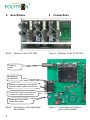
2 Anschlüsse
Bild 2 Module in der SPM 1000
Bild 3 Anschlüsse und Pegelsteller
des Module
2 Connections
Figure 2 Modules in the SPM 1000
Figure 3 Connections and attenu-
ators of the module
Audiopegel
Audio level
Steckbrücke Video extern/intern
Jumper for video extern/intern
Ausgangs-Pegelsteller
Output attenuator
Eingang
Input
Externes Videosignal und Masse
External video signal and chassis

5
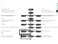
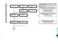
3 Programmierung der
Module
1. Nach der Bestückung der
Grundeinheit und dem Aufbau
der Eingangsverteilung erfolgt
die Programmierung der Module
gemäß des auf den folgenden
Seiten abgebildeten Program-
mierablaufs.
2. Hierbei ist zu beachten, dass der
dem eingesetzten Grundgerät
entsprechende Programmierab-
lauf gewählt wird.
Die Anwahl und Bestätigung der
Bedienschritte erfolgt über die
Tastatur unterhalb des Displays.
3. Nach Programmierung aller Mo-
dule einer Grundeinheit sollten
die Ausgangspegel über den je-
weiligen Ausgangspegelsteller
(Bild 3) auf den gleichen Wert
eingestellt werden.
HINWEIS
Nach einem Steckplatzwechsel
oder dem Übertragen von Daten
mit einem CopyKey, müssen die-
se neu bestätigt werden.
ACHTUNG
Die im Grundgerät benötigte
Softwareversion zur fehlerfrei-
en Programmierung der Modu-
le, ist auf dem Modul angege-
ben oder kann der Software-
matrix unter www.polytron.de
Service
Software ent-
nommen werden.
3 Programming procedure
for the modules
1. After the assembly of the base
unit and the construction of the
entrance distribution, the mod-
ules have to be programmed in
accordance with the program
sequence shown on the follow-
ing pages.
2. Note, that the program sequence
should correspond to the as-
signed base unit.
The selection and confirmation
of the operating steps is carried
out by the buttons below the dis-
play.
3. After programming the modules,
output levels should be adjusted
to a common value by the at-
tenuators placed on each mod-
ule (Figure 3).
NOTE
After changing the module slot
position of a module or data have
been transferred by a CopyKey,
the data must be confirmed a-
gain.
ATTENTION
The required software version
of the basic unit for error-free
programming is specified on
the module label or can be
seen in the software matrix at
www.polytron.de
Service
Software.

6
6
.
S
6.
..
.
4
P L 0 1 P L 0 5 P L 1 0
t
Y 3 3
8 7.
..
. 5
9
2.
..
.
5 1 0
8.
..
.
0
S t 1 S t 3 S t 6
S E t C S E t F
S 0 2 C 2 1 C 7 5
8
7.
..
.
0 4 7
2.
..
.
0 8 6
2.
..
.
0
Eingangsfrequenz des Kanals wählen (MHz)
Modultyp
Anzeige im Standby modus
Anzeige der Softwareversion der Grundeinheit
Taste
M
drücken, um das Menü zu starten
Den zu programmierenden Modulplatz wählen und
durch Drücken der Taste
M
bestätigen
Module type
Choose input frequency for the channel (MHz)
Auswahl: Kanaleingabe (C)
①
oder
Frequenzeingabe (F)
②
Select: channel setting (C)
①
or
frequency setting (F)
②
standby
Press key
M
to start the menu
Shows the software version of the basic unit
Choosing the module place to be programmed and
confirming by pressing the button
M
.
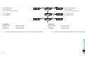
(Channel center frequency)
TV-standardTV-Standard
(Kanalmittenfrequenz)
(D/K, I, M, N)
Einstellung Ausgangskanal (B/G) Select output channel (B/G)
oder or
(D/K, I, M, N)
Einstellung Ausgangsfrequenz (MHz)
in 250-kHz-Schritten in 250-kHz-steps
Select output frequency (MHz)
M
+
-
M
M
+
-
+
-
M
M
+
-
+
-
M
M
+
Kanaleingabe
channel setting
①
①①
①
Frequenzeingabe
frequency setting
②
②②
②

7
7
F 0 0 F - 0 7 F - 1 2
t o n t o F F
P L 0 1 P L 0 5 P L 1 0
Standard 5= L Standard 6 = B/B
TV-standard
*) *)
Nach der Feinabstimmung der Module muss die Anlage neu eingepegelt werden! After the fine tuning of the modules the plant must be adjusted again!
standard 1 = B/G standard 2 = D/K
standard 3 = I
Frequency IF-finetuning *)
F -07 = Standard F -07 = standard
F -12 = max. ZF-Frequenzversatz F -12 = max. IF frequency offset
ZF-Feinabstimmung *)
standard 4 = M,N
standard 5= L standard 6 = B/B
t on = Testbild ein
t off = Testbild aus
t on = test pattern on
t off = test pattern off
TV-Standard
Standard 1 = B/G Standard 2 = D/K
Standard 3 = I Standard 4 = M,N
+
-
+
M
+
M
+
-
M

8
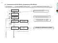
3.2 Programmierung SPM 1000 digi / Programming SPM 1000 digi
8
→ Program
↨ Service
Compact Headend
SPM1000 DIGI X.X.
← PL01 SPM-FMTV
→
↨ PL02 SPM-XXX
Zu programmierenden Modulsteckplatz mit
▼▲ wä
h
len
select module slot to be programmed by ▼▲
gedrückt halten bis Anzeige aktiviert ist
keep pressed until display is activated
← FM-IN Freq. →
↨ TV Standard
← TV Standard →
↨ Set Chan/Freq.
Eingangsfrequenz wählen
87,5
-
108 MHz
select intput frequency 87,5 - 108 MHz
Input Frequency
↨ 92,5 MHz →
TV Standard
↨ B/G →
◄ : zurück/ back
► : weiter + bestätigen /
forward
+ co
n
firm
▼▲ : hoch + runter
(scrollen) / up + down (scroll
)
TV-Standard mit
▼▲
wählen und durch ► bestätigen!
select TV standard by
▼▲
and confirm data by pressing ► !
1

9
ZF
-
Feinabstimmung wählen
/
select IF
-
finetuning
F-07 Standard
F-12 max. ZF-Frequenzversatz /
max. IF frequency offset
Einzelne Ziffern der Ausgangsfrequenz mit
◄
a
n
wählen
und mit ▼▲ auswählen.
Achtung: mit Drücken von ► werden die Daten bestätigt;
Choose individual digit of the output frequency by ◄ and
select number by ▼▲
Attention: by pressing
►
the data will be co
n
firmed!;
Ausgangskanal mit
▼▲
auswählen und
Auswahl mit ► bestätigen!
Choose Output channel by ▼▲ and
confirm Selection by pressing ► !
Testbildstatus
(
On/O
ff) mit
▼▲
auswählen.
Daten durch Drücken von ► bestätigen
Choose testpicture setting (On/Off) by ▼▲
Confirm data by pressing ► !
←
Set Chan/Freq.
→ ↨ IF-Finetuning
← IF-Finetuning →
↨ Testpicture
← Testpicture →
↨ FM-IN Freq.
Testpicture
↨ On →
Set output by
↨ Frequency →
IF-Finetuning
↨ F-07 →
Set output by
↨ Channel →
Output Frequency
↨ 407.50 MHz →
Output Channel
↨ C 21 →
1
9

10
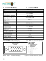
4 Technische Daten 4 Technical Data
4.1 SUB-D Anschlussbelegung 4.1 SUB-D connection pinning
Bild 4 SUB-D Anschlussbelegung Figure 4 SUB-D connection pinning
Typ SPM-FM/TV
Eingang / Input
Frequenzbereich /
Frequency range
87,5 - 108 MHz
Eingangspegel / Input level min. 15 dBµV
Externer Videoeingang
Extern video input level
1 V
pp
(±1 dB) 75 Ω
AV-Anschluss
AV-connection
SUB-D
TV-Normen
TV-Normen
TV-standards
B/G, D/K, I, M, N
Ausgang / Output
Frequenzbereich /
Frequency range
47 – 862 MHz
Ausgangspegel
Output level
95 dBµV
Anschluss / Connector F / 75 Ω
Sonstiges / Others
Leistungsaufnahme
Power consumption
3 W
Gewicht / Weight 0,42 kg
Modulgehäuse (B x H xT) /
Module housing (w x h x d)
31 x 117 x 235 mm
SUB
-
D Buchse
SUB-D socket
1 Audioeingang links
audio input left
2 Videoeingang
video input
6 Audioeingang rechts
audio input right
8 Masse
ground
11 Masse
ground
Ansicht von oben
Top view
1
6 10
5
11
15

11

12
Polytron-Vertrieb GmbH
Postfach 10 02 33
75313 Bad Wildbad
Zentrale/Bestellannahme
H.Q. Order department + 49 (0) 70 81/1702 - 0
Technische Hotline
Technical hotline + 49 (0) 70 81/1702 - 12
Telefax + 49 (0) 70 81) 1702 - 50
Internet http://www.polytron.de
eMail [email protected]
Technische Änderungen vorbehalten
Subject to change without prior notice
Copyright © Polytron-Vertrieb GmbH
-
 1
1
-
 2
2
-
 3
3
-
 4
4
-
 5
5
-
 6
6
-
 7
7
-
 8
8
-
 9
9
-
 10
10
-
 11
11
-
 12
12


POLYTRON SPM-FM/TV FM in TV channel modulator Bedienungsanleitung
- Typ
- Bedienungsanleitung
in anderen Sprachen
Verwandte Papiere
-
POLYTRON SPM-MS/MST-Q AV/TV modulator stereo Bedienungsanleitung
-
-
-
-
-
-
-
-
-

