
1
DVB-S/-S2 DVB-T/-T2 DVB-C
DVB-C / DVB-T
Twin-AV Modul / module
SPM-UT-AVT
Bedienungsanleitung/
Operating manual
0901867

2
ACHTUNG Vor Arbeiten am Grundgerät
bitte unbedingt die Sicherheitsbestimmungen
des Grundgeräts sorgfältig lesen!
ACHTUNG Diese Baugruppe enthält ESD-
Bauteile!
ESD-Schutzmaßnahmen beachten!
HINWEIS
Der Inhalt dieses Firmenhandbuches ist urhe-
berrechtlich geschützt und darf ohne Geneh-
migung des Erstellers weder ganz noch teil-
weise in irgendeiner Form vervielfältigt oder
kopiert werden. Änderungen in diesem Fir-
menhandbuch, die ohne Zustimmung des Er-
stellers erfolgen, können zum Verlust der Ge-
währleistung bzw. zur Ablehnung der Produkt-
haftung seitens des Herstellers führen. Für
Verbesserungsvorschläge ist der Ersteller
dankbar.
Ersteller:
Polytron-Vertrieb GmbH
Postfach 10 02 33
75313 Bad Wildbad
ATTENTION Before working on the basic
unit please read the safety precautions of the
base unit carefully!
ATTENTION This unit is equipped with
ESD-components!
Observe ESD protective measures!
NOTE
The contents of this company manual are cop-
yrighted and must not be duplicated or copied
in any form, either partially or in full, without the
prior consent of the creator. Changes in this
company manual which are carried out without
consent of the creator can lead to the loss of
the guarantee or to the rejection of the product
liability on the part of the manufacturer. The
creator is grateful for suggestions for improve-
ment.
Creator:
Polytron-Vertrieb GmbH
Postfach 10 02 33
75313 Bad Wildbad
Germany

3
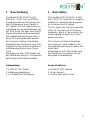
1 Beschreibung
Das Modul SPM-UT-AVT ist ein
DVB-S(2)- / DVB-T(2)- und DVB-C-
Empfangsmodul zur Umsetzung von
zwei Programmen eines Kanals in
AV-Signale. Das AV-Signal kann an-
schließend von einem Modulator aus
der SPM-Serie, der über eine Sub-D-
Steckverbindung mit dem eingesetz-
ten Digitalmodul verbunden wird, in
einen TV-Kanal gewandelt werden.
Der Common Interface Steckplatz
ermöglicht das Einstecken eines Kar-
tenlesers für das entsprechende Ent-
schlüsselungssystem einer Smart-
Card.
Abhängig von dem CAM-Modul und
der Smartkarte können 2 Programme
gleichzeitig entschlüsselt werden.
Lieferumfang
1 x SPM-UT-AVT Modul
1 x Bedienungsanleitung
1 x Frontplatte mit Schrauben
1 Description
The module SPM-UT-AVT is a DVB-
S(2) / DVB-T(2) and DVB-C reception
module for converting two programs
of a channel into AV signals.
The AV signal can then be converted
into a TV channel by a SPM series
modulator, which is connected to the
inserted digital module via a sub-D
plug connection.
The Common Interface slot allows
you to plug in a card reader for the
corresponding decryption system of a
smart card.
Depending on the CAM module and
the Smartcard, 2 programs can be
decrypted simultaneously.
Scope of delivery
1 x SPM-UT-AVT module
1 x User manual
1 x Cover plate with screws

4
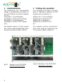
2 Inbetriebnahme
Die Bestückung des Grundgerätes
erfolgt in Abwechslung zwischen ei-
nem SPM-Modul und einem Modula-
tor, d.h.
Steckplatz 1: Twin-Modulator
Steckplatz 2: SPM-UT-AVT-Modul
Steckplatz 3: Twin-Modulator
Steckplatz 4: SPM-UT-AVT-Modul
usw.
Die Module müssen mit den jeweili-
gen Sub-D-Verbindungskabeln mitei-
nander verbunden werden. (Bild 2)
Bild 2 Module in der SPM 2000
(Abbildung beispielhaft)
2 Putting into operation
The assembly of the base unit takes
place in alternation between a SPM
module and a modulator, i.e.
Module slot 1: Twin modulator
Module slot 2: SPM-UT-AVT
Module slot 3: Modulator
Module slot 4: SPM-UT-AVT
etc.
The modules must be connected to
each other using the respective sub-
D connection cables. (Figure 2)
Figure 2 Modules in the SPM 2000
(Illustration example)

5
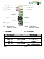
2.1 Anschlüsse
Eingang DVB-T/-T2/-C
Eingang DVB-S/-S2
Ausgang AV
USB für Update
Bild 3 Anschlüsse am
SPM-UT-AVT Modul
2.2 LED-Anzeige
2.1 Connections
Input DVB-T/-T2/-C
Input DVB-S/-S2
Output AV
USB for Update
Figure 3 Connections on
SPM-UT-AVT module
2.2 LED indication
LNB Spannung /
LNB voltage
Signal
LED-Anzeige /
LED indicator
AUS / OFF
OK
Grün / Green
AUS / OFF
Nicht / Not OK
Grün blinkend /
Green flashing
AN / ON
OK
Orange
AN / ON
Nicht / Not OK
Rot / Orange blinkend
Red / Orange flashing
Bild 4 Figure 4
Tuner-LED
USB-LED

6
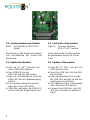
2.3 Kartenaufnahme des Moduls
Bild 5 Schnittstelle SPM-UT-AVT
Modul
Kartenleser in das Modul einschieben
und anschließend die Smart-Card
einstecken.
2.4 Update des Modules
a) Das File „UT_AVT_Vxxx.bin“ auf
einen USB-Stick kopieren.
b) Den USB-Stick in den
USB-Slot stecken und warten.
c) Nach ca. 30 Sekunden leuchtet die
USB-LED und der Updatevorgang
startet.
d) Der Updatevorgang ist beendet
wenn die Tuner-LED blinkt.
e) USB-Stick abziehen, die USB-LED
erlischt und das Modul startet neu.
2.3 Card slots of the module
Figure 5 Common interface
SPM-UT-AVT module
Insert card reader into the module
and afterwards plug in the Smart-
Card.
2.4 Update of the module
a) Copy the “UT_AVT_Vxxx.bin” to a
USB memory stick.
b) Insert the USB stick into the USB
slot and wait.
c) After approximately 30 seconds,
the USB LED will light up and the
update process will start.
d) The update process is terminated
when the tuner LED flashes.
e) Remove the USB stick, the USB
LED turns off and the module re-
starts.

7
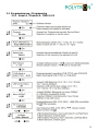
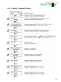
3 Programmierung der
Module
Nach der Bestückung der Grundein-
heit und dem Aufbau der Eingangs-
verteilung erfolgt zunächst die Pro-
grammierung der Grundeinheit und
der Modulatoren gemäß der jeweils
beiliegenden Anleitung.
Die anschließende Programmierung
der Digitalmodule geschieht folgen-
dermaßen:
1. Antennenmessgerät zur Kontrolle
des Ausgangssignals am HF-
Ausgang der Kopfstation an-
schließen. Die Programmierung
ist sowohl über das Bildschirm-
menü, als auch über das Display
möglich.
2. Modulatormodul auf den ge-
wünschten Ausgangskanal, ge-
mäß der dem Modulator beilie-
genden Anleitung programmie-
ren. Zur Programmierung eines
Digitalmoduls muss das Messge-
rät bzw. der Bildschirm auf den
entsprechenden Ausgangskanal
des Modulators eingestellt wer-
den. (Bei Twin-Modulatoren zeigt
der Ausgangskanal A auch die
Parameter des zweiten Digitalzu-
ges an.)
3. Programmierung der Digitalmo-
dule gemäß des auf den folgen-
den Seiten abgebildeten Pro-
grammierablaufs
Die Anwahl und Bestätigung der
Bedienschritte erfolgt über die
Tastatur unterhalb des Displays.
3 Programming procedure
for the modules
After the assembly of the base unit
and the construction of the entrance
distribution, the base unit and the
modulators have to be programmed
in accordance with the respectively
enclosed guidance.
The manual programming of the digi-
tal modules is carried out as follows:
1. Connect an antenna meter to the
output of the head-end station to
control the output signal. The
programming is possible via the
on-screen menu as well as via
the display.
2. Program modulator module on
the desired output channel, in ac-
cordance with the enclosed in-
struction. For the programming of
a digital module the measuring
instrument and/or the screen
must be adjusted to the corre-
sponding output channel of the
modulator.
(At Twin modulators, the initial
channel A also displays the pa-
rameters of the second digital
channel.)
3. Program the digital modules in
accordance with the program se-
quence shown on the following
pages.
The selection and confirmation of
the operating steps is carried out
via the keyboard below the dis-
play.

8
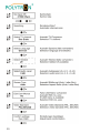
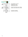
HINWEIS
Während des Programmiervor-
gangs werden sowohl auf dem
Display der Grundeinheit als auch
auf der Bildschirmanzeige Pro-
grammierungshinweise angezeigt!
Nach einem Steckplatzwechsel
müssen die Daten neu bestätigt
werden.
ACHTUNG
Die im Grundgerät benötigte
min. Softwareversion zur fehler-
freien Programmierung der Mo-
dule, ist auf dem Modul ange-
geben.
NOTE
During the programming process,
programming references are dis-
played on the base unit and on
the screen display!
After a slot change the data has to
be confirmed again.
ATTENTION
The min. required software ver-
sion of the base unit for error-
free programming, is specified
on the module.
Beispiel / Example
Programmtasten SPM 2000 / Program button SPM 2000

9
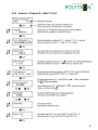
3.1 Programmierung / Programming
3.1.1 Kanal A / Channel A DVB-S/-S2

10

11
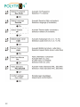
3.1.2 Kanal A / Channel A DVB-T/-T2/-C

12

13
3.1.3 Kanal B / Channel B (Slave)

14

15
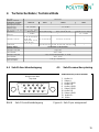
4 Technische Daten / Technical Data
Typ / Type
Artikel-Nr. / Article No.
HF-Eingänge / RF-Inputs DVB-S/-S2 DVB-T DVB-T2 DVB-C
Anschluss / Connection
Eingangspegel / Input level
Frequenzbereich /
Frequency range
950…2150 MHz
LNB-Steuerung / LNB control 14/18 V / 22 kHz / DiSEqC
Demodulation 8PSK, QPSK QPSK, QAM 16 / 64 QPSK, QAM 16 / 64 / 256 QAM 16 / 32 / 64 / 128 / 256
Symbolrate / Symbol rate
DVB-S/-S2
1…45 MS/s 0,2…7,2 MS/s
Code-Rate / Code rate
DVB-S / QPSK: 1/4, 1/3,
2/5, 1/2, 3/5, 2/3, 3/4, 4/5,
5/6, 8/9, 9/10
DVB-S2 / 8PSK: 3/5, 2/3,
3/4, 5/6, 8/9, 9/10
1/2, 2/3, 3/4, 5/6, 7/8 1/2, 3/5, 2/3, 3/4, 4/5, 5/6 /
Guard Intervall /
Guard interval
/ 1/4, 1/8, 1/16, 1/32 1/4, 5/32, 1/8, 5/64, 1/16, 1/32, 1/64, 1/128 /
Ausgang / Output
Anschluss / Connection
Videopegel / Video level
Video-Bandbreite /
Video bandwidth
Audiopegel / Audio level
Audio-Bandbreite /
Audio bandwidth
Leistungsaufnahme /
Power consumption
SPM-UT-AVT
5529838
zum Modulator / to the modulator
15-polige Sub-D-Buchse / 15-pin female sub-D
/
110…862 MHz
/
2 x F-Buchse / F-connector (female)
50…80 dBµV
1 Vpp / 75 Ω
20 Hz…5 MHz
1 Vpp / 10 kΩ (3-dB-Schritte/steps, -6…+6 dB)
40 Hz…15 kHz
11 W (typ., ohne/without CI)
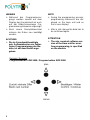
4.1 Sub-D Anschlussbelegung 4.1 Sub-D connection pinning
Bild 6 Sub-D Anschlussbelegung Figure 6 Sub-D pin assignment
Sub-D Buchse, Sub-D socket
1 Audio A L
2 Video A
5 Audio B GND
6 Audio A R
8 Audio A GND
9 Video B GND
10 Audio B R
11 Video A GND
13 Audio B L
14 Video
Ansicht von oben
Top view
1
6
10
5
11
15

16
Polytron-Vertrieb GmbH
Postfach 10 02 33
75313 Bad Wildbad
Zentrale/Bestellannahme
H.Q. Order department + 49 (0) 70 81/1702 - 0
Technische Hotline
Technical hotline + 49 (0) 70 81/1702 - 0
Telefax + 49 (0) 70 81) 1702 - 50
Internet http://www.polytron.de
eMail [email protected]
Technische Änderungen vorbehalten
Subject to change without prior notice
Copyright © Polytron-Vertrieb GmbH
-
 1
1
-
 2
2
-
 3
3
-
 4
4
-
 5
5
-
 6
6
-
 7
7
-
 8
8
-
 9
9
-
 10
10
-
 11
11
-
 12
12
-
 13
13
-
 14
14
-
 15
15
-
 16
16


POLYTRON SPM-UTAVT DVB-S/S2/T/T2/C into AV twin Bedienungsanleitung
- Typ
- Bedienungsanleitung
- Dieses Handbuch eignet sich auch für
in anderen Sprachen
Verwandte Artikel
-
POLYTRON SPM-S2AVT Twin digital DVB-S/S2 in AV Bedienungsanleitung
-
-
-
-
-
-
-
-
POLYTRON SPM-DQT DVB-S-QAM module Bedienungsanleitung
-