Minebea Intec YPS02-XV24 Power Supply for Installation in Hazardous Areas Bedienungsanleitung
- Typ
- Bedienungsanleitung

Installation Instructions | Betriebsanleitung | Notice d’installation
Istruzioni per l’installazione | Instrucciones de funcionamiento
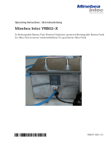
Minebea Intec Power Supply YPS02-XV24
Power Supply for Installation in Hazardous Areas
Netzgerät für den Einsatz im explosionsgefährdeten Bereich
Bloc d’alimentation pour l’utilisation en atmosphère explosible
Alimentatore per l’impiego nelle aree a rischio di esplosione
Alimentador de red para el uso en zonas con riesgo de explosión
98647-003-46
98647-003-46

Installation Instructions | Betriebsannleitung 3
English – page 3
Deutsch – Seite 18
Français – page 33
Italiano – pagina 48
Español – página 63
Declaration of Conformity 88

Installation Instructions | Betriebsannleitung 3
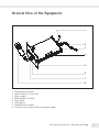
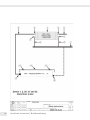
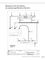
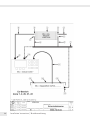
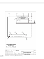
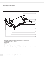
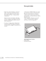
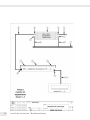
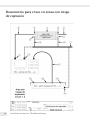
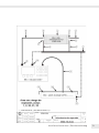
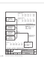
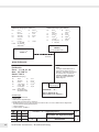
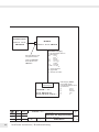
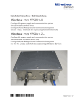
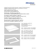
1 Ground/earth terminal
2 Input cable (24 V ±10% DC)
3 Power supply
4 Manufacturer’s ID label
5 Front panel
6 Cable gland
7 Ground/earth terminal
8 Connector for an intrinsically safe power supply
General View of the Equipment
1
2
3
5
6
7
4
8

4 Installation Instructions | Betriebsannleitung Installation Instructions | Betriebsannleitung 5
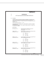
Contents Warnings and
Safety Precautions
3 General View of the Equipment
4 Contents
4 Warnings and Safety Precautions
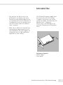
5 Intended Use
6 Installation
7 Specifications
7 Accessories
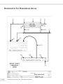
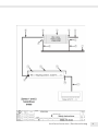
8 Documents for Hazardous Areas
The following symbols are used in
these instructions:
§ indicates required steps
$ indicates steps required only under
certain conditions
> describes what happens after you have
performed a particular step
– indicates an item in a list
! indicates a hazard
– The equipment complies with Directive
94/9/EC for use in the following haz-
ardous areas: Zone 1 and 2 (gases) and
Zone 20, 21 and 22 (dusts).
– When used in hazardous areas in which
combustible dusts are present, the IP65
protection of the equipment must be
intact. For this reason, it is essential
that installation and maintenance
are performed with extreme care;
in particular:
– Make sure all seals are installed
– Observe all instructions carefully
when installing the cover
– Tighten all fastening screws
– Tighten all cable glands and make
sure they are installed in accordance
with instructions
! Disconnect the equipment from power
before opening the equipment housing
– Equipotential bonding conductors are
installed on the housing.
Make sure to ground (earth) the power
supply.
– The power supply may be operated only
within an ambient temperature range of
-20° to +40°C (-4° to +104°F).
– When used in a hazardous area in which
combustible dusts are present, clean
the power supply regularly to prevent
excessive build-up of dust. In a Zone
20 hazardous area, the maximum per-
missible dust layer thickness is 5 mm.
– Installation, maintenance and repair
work should be performed only by ser-
vice technicians trained and authorized
by Minebea Intec .

Installation Instructions | Betriebsannleitung 5
Intended Use
– Any work on the device that is not
performed in accordance with these
instructions and acknowledged techni-
cal standards will result in forfeiture of
the approval for use in hazardous areas,
and of all claims under the manufac-
turer’s warranty.
– Make sure to observe all national laws
and regulations governing the use of
such equipment. Ask your supplier for
information on the legal regulations
applicable in your country.
The YPS02-XV24 power supply must
be connected to 24 V DC voltage.
It supplies intrinsically safe electric
circuits for supply of intrinsically safe
Minebea Intec equipment.
Please refer to the drawings in the
enclosed “Documents for Hazardous
Areas.”
Equipment Supplied
– Power supply
– Front panel

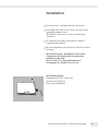
Installation Instructions | Betriebsannleitung 7
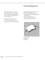
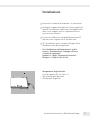
Installation
! Observe all warnings and safety precautions.
! Always disconnect the power supply before
beginning any work on the equipment.
Never perform any work on the equipment while
it is energized.
! Work that affects the IP protection must be carried
out with extreme care.
! Any installation work that does not conform to the
instructions in this manual will result in forfeiture of
all claims under the manufacturer’s warranty.
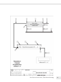
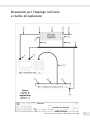
– Make sure to observe the safety information on
sheets 6 and 7 of Drawing No. 65684-740-25-A4
in the attached “Documents for Hazardous Areas”
for important details on installation.
Pin assignments:
Input cable (24 V ±10% DC)
– brown stranded wire (positive pole)
– blue stranded wire (negative pole)

Installation Instructions | Betriebsannleitung 7
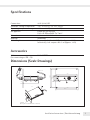
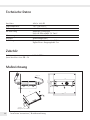
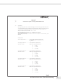
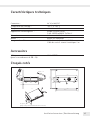
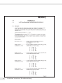
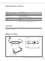
Specifications
Connection: 24 V (±10%) DC
Allowable storage temperature –25° to +70°C (-13° to +158°F)
Operating temperature range: –20° to +40°C (-4° to +104°F)
EX-approval KEMA 03 ATEX2164X
II 2G 1D EEX m[ib]IIC T4 T80°C
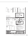
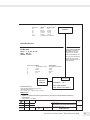
Dimensions: 142 mm + 130 mm + 38 mm
Housing: Aluminum
Cable lengths: Input cable (24 V ±10% DC): 5 m (approx. 16 ft)
Intrinsically safe output cable 5 m (approx. 16 ft)
Accessories
Cable YCC02XRBEX
(for connecting an EB...-IX)
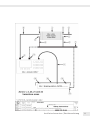
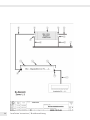
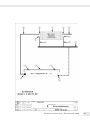
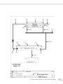
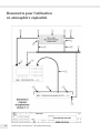
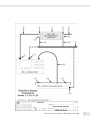
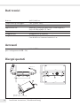
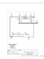
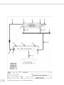
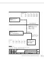
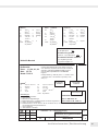
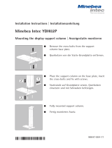
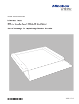
Dimensions (Scale Drawings)
1: 2
optional
(front panel for installation in a 19" rack)
183.1
2.5
Length: 5 m
Length: 5 m 130
31
37.9
122.4
128.4
127
141.9

8 Installation Instructions | Betriebsannleitung Installation Instructions | Betriebsannleitung 9
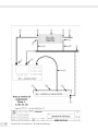
Documents for Hazardous Areas

Installation Instructions | Betriebsannleitung 9

10 Installation Instructions | Betriebsannleitung Installation Instructions | Betriebsannleitung 11

Installation Instructions | Betriebsannleitung 11

12 Installation Instructions | Betriebsannleitung Installation Instructions | Betriebsannleitung 13

Installation Instructions | Betriebsannleitung 13

14 Installation Instructions | Betriebsannleitung Installation Instructions | Betriebsannleitung 15

Installation Instructions | Betriebsannleitung 15

16 Installation Instructions | Betriebsannleitung Installation Instructions | Betriebsannleitung 17

Installation Instructions | Betriebsannleitung 17

18 Installation Instructions | Betriebsannleitung Installation Instructions | Betriebsannleitung 19
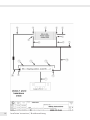
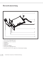
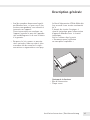
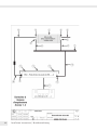
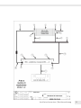
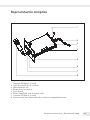
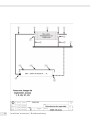
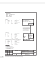
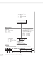
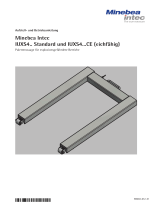
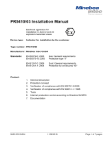
Übersichtsdarstellung
1
2
3
5
6
7
4
8
1 PA-Anschluss (Erdungsklemme)
2 Eingangskabel (24 V ±10% DC)
3 Netzgerät
4 Typenschild
5 Frontplatte
6 Kabelverschraubung
7 PA-Anschluss (Erdungsklemme)
8 Anschlussstecker für eine eigensichere Spannungsversorgung

Installation Instructions | Betriebsannleitung 19
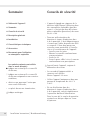
Inhalt Warn- und
Sicherheitshinweise
18 Übersichtsdarstellung
19 Inhalt
19 Warn- und Sicherheitshinweise
20 Verwendungszweck
21 Installation
22 Technische Daten
23 Zubehör
29 Dokumente für den Einsatz im
explosionsgefährdeten Bereich
Folgende Symbole werden in dieser
Anleitung verwendet:
§ steht vor Handlungsanweisungen
$ steht vor Handlungsanweisungen, die
nur unter bestimmten Voraussetzungen
ausgeführt werden sollen
> beschreibt das, was nach einer ausge-
führten Handlung geschieht
– steht vor einem Aufzählungspunkt
! weist auf eine Gefahr hin
– Das Gerät erfüllt die Anforderungen
der Richtlinie 94/9/EG für den Einsatz
in Gasexplosionsgefährdeten Bereichen
der Zone 1 und 2, sowie in Staub-
explosionsgefährdeten Bereichen der
Zone 20, 21 und 22.
– Für den Einsatz im Staubexplosions-
gefährdeten Bereich muss der IP-Schutz
(IP65) sichergestellt sein. Die Instal-
lation und Wartung erfordert deshalb
besondere Aufmerksamkeit:
– Alle Dichtungen einsetzen
– Deckel vorschriftsmäßig montieren
– die Schrauben fest anziehen
– Kabelverschraubungen fest anziehen
und vorschriftsmäßig montieren
! Vor jedem Öffnen das Gerät von der
Versorgungsspannung trennen.
– An dem Gehäuse befinden sich Poten-
zialausgleichsanschlüsse.
Das Gerät erden.
– Das Gerät nur in einer Umgebungstem-
peratur von -20° C bis +40°C betreiben.
– Bei Verwendung in Staubexplosions-
gefährdeten Bereichen das Neztgerät
regelmäßig von Staub zu befreien. In
Zone 20 ist nur eine maximale Staub-
schichtdicke von 5mm zulässig.

20 Installation Instructions | Betriebsannleitung Installation Instructions | Betriebsannleitung 21
Verwendungszweck
– Ein Eingriff in das Gerät sollte nur
durch von Minebea Intec geschultes
und autorisiertes Personal erfolgen.
Ein unsachgemäßer Eingriff führt zum
Verlust der Ex-Zulassung und aller
Garantieansprüche.
– Nationale Gesetze, Normen und
Vorschriften sind zu beachten.
Den Lieferanten nach den in Ihrem
Land geltenden Bestimmungen fragen.
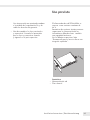
Das Netzgerät YPS02-XV24 wird an 24 V
Gleichspannung angeschlossen.
Es liefert eigensichere Stromkreise zur
Versorgung eigensicherer Minebea Intec
- Betriebsmittel.
Siehe die Zeichnugen unter
„Dokumente für den Einsatz im
explosionsgefährdeten Bereich“.
Lieferumfang
– Netzgerät
– Frontplatte
Seite wird geladen ...
Seite wird geladen ...
Seite wird geladen ...
Seite wird geladen ...
Seite wird geladen ...
Seite wird geladen ...
Seite wird geladen ...
Seite wird geladen ...
Seite wird geladen ...
Seite wird geladen ...
Seite wird geladen ...
Seite wird geladen ...
Seite wird geladen ...
Seite wird geladen ...
Seite wird geladen ...
Seite wird geladen ...
Seite wird geladen ...
Seite wird geladen ...
Seite wird geladen ...
Seite wird geladen ...
Seite wird geladen ...
Seite wird geladen ...
Seite wird geladen ...
Seite wird geladen ...
Seite wird geladen ...
Seite wird geladen ...
Seite wird geladen ...
Seite wird geladen ...
Seite wird geladen ...
Seite wird geladen ...
Seite wird geladen ...
Seite wird geladen ...
Seite wird geladen ...
Seite wird geladen ...
Seite wird geladen ...
Seite wird geladen ...
Seite wird geladen ...
Seite wird geladen ...
Seite wird geladen ...
Seite wird geladen ...
Seite wird geladen ...
Seite wird geladen ...
Seite wird geladen ...
Seite wird geladen ...
Seite wird geladen ...
Seite wird geladen ...
Seite wird geladen ...
Seite wird geladen ...
Seite wird geladen ...
Seite wird geladen ...
Seite wird geladen ...
Seite wird geladen ...
Seite wird geladen ...
Seite wird geladen ...
Seite wird geladen ...
Seite wird geladen ...
Seite wird geladen ...
Seite wird geladen ...
Seite wird geladen ...
Seite wird geladen ...
Seite wird geladen ...
Seite wird geladen ...
Seite wird geladen ...
Seite wird geladen ...
Seite wird geladen ...
Seite wird geladen ...
Seite wird geladen ...
Seite wird geladen ...
Seite wird geladen ...
Seite wird geladen ...
Seite wird geladen ...
Seite wird geladen ...
-
 1
1
-
 2
2
-
 3
3
-
 4
4
-
 5
5
-
 6
6
-
 7
7
-
 8
8
-
 9
9
-
 10
10
-
 11
11
-
 12
12
-
 13
13
-
 14
14
-
 15
15
-
 16
16
-
 17
17
-
 18
18
-
 19
19
-
 20
20
-
 21
21
-
 22
22
-
 23
23
-
 24
24
-
 25
25
-
 26
26
-
 27
27
-
 28
28
-
 29
29
-
 30
30
-
 31
31
-
 32
32
-
 33
33
-
 34
34
-
 35
35
-
 36
36
-
 37
37
-
 38
38
-
 39
39
-
 40
40
-
 41
41
-
 42
42
-
 43
43
-
 44
44
-
 45
45
-
 46
46
-
 47
47
-
 48
48
-
 49
49
-
 50
50
-
 51
51
-
 52
52
-
 53
53
-
 54
54
-
 55
55
-
 56
56
-
 57
57
-
 58
58
-
 59
59
-
 60
60
-
 61
61
-
 62
62
-
 63
63
-
 64
64
-
 65
65
-
 66
66
-
 67
67
-
 68
68
-
 69
69
-
 70
70
-
 71
71
-
 72
72
-
 73
73
-
 74
74
-
 75
75
-
 76
76
-
 77
77
-
 78
78
-
 79
79
-
 80
80
-
 81
81
-
 82
82
-
 83
83
-
 84
84
-
 85
85
-
 86
86
-
 87
87
-
 88
88
-
 89
89
-
 90
90
-
 91
91
-
 92
92


Minebea Intec YPS02-XV24 Power Supply for Installation in Hazardous Areas Bedienungsanleitung
- Typ
- Bedienungsanleitung
in anderen Sprachen
Verwandte Artikel
-
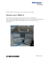
 Minebea Intec YRB02-X Ex Rechargeable Battery Pack Bedienungsanleitung
-
 Minebea Intec Pit Frame Edges YEG01...08 For Midrics Weighing Platforms of the MW1… | MW2… | MAPP1...4 | MAPS1...4Series Bedienungsanleitung
-
 Minebea Intec IS06BBE-SX, IS2CCE-SX, IS6CCE-HX, IS16EDE-HX, IS34EDE-HX, IS64EDE-SX, IS150IGG-HX, IS300IGG-HX Wägeplattformen für explosionsgefährdete Bereiche Bedienungsanleitung
-
 Minebea Intec Configurable power supply and communication system for use inside hazardous areas Bedienungsanleitung
-
 Minebea Intec Mounting the display support column Bedienungsanleitung
-
 Minebea Intec IUXS4 Palettenwaage für explosionsgefährdete Bereiche Bedienungsanleitung
-
 Minebea Intec IF, IF 0CE Bedienungsanleitung
-
 Minebea Intec Pallet Scale/Flat-bed Scale: Option Y2 for Use in Zone 2 and 22 Hazardous Areas Bedienungsanleitung
-
 Minebea Intec IFXS4 Durchfahrwaage für explosionsgefährdete Bereiche Bedienungsanleitung
-
 Minebea Intec PR 5410/03 Installationsanleitung


