Minebea Intec Pallet Scale/Flat-bed Scale: Option Y2 for Use in Zone 2 and 22 Hazardous Areas Bedienungsanleitung
- Typ
- Bedienungsanleitung

98647-003-63
98647-003-63
98647-003-63
Installation Instructions and Safety Information | Installation und Sicherheitshinweise |
Installation et conseils de sécurité | Istruzioni per l’installazione e di sicurezza |
Instalación y advertencias de seguridad
Pallet Scale/Flat-bed Scale: Option Y2
for Use in Zone 2 and 22 Hazardous Area
Palettenwaage | Durchfahrwaage: Option Y2
für den Einsatz in explosionsgefährdeten Bereichen der Zone 2 und 22
Pèse-palettes | Bascules surbaissées : Option Y2
pour l’utilisation en atmosphères explosives des zones 2 et 22
Pesapallet | Basamenti extra piatti: Opzione Y2
per le aree a rischio di esplosione delle zone 2 e 22
Báscula de paletas | báscula de bajo perfil : opción Y2
para las áreas con peligro de explosión, zonas 2 y 22
IUS4.. (Standard) and IUS4..CE
(Verifiable) Models
IFS4.. (Standard) and IFS4..CE
(Verifiable) Models
IUS4... Standard und IUS4...CE (eichfähig)
IFS4... Standard und IFS4...CE (eichfähig)
IUS4... non approuvé et IUS4...CE
(pour usage en métrologie légale)
IFS4... non approuvé et IFS4...CE
(pour usage en métrologie légale)
IUS4... standard e IUS4...CE (omologabile)
IFS4... standard e IFS4...CE (omologabile)
IUS4... estándar e IUS4...CE (verificable)
IFS4... estándar e IFS4...CE (verificable)

2 Pallet Scale/Flat-bed Scale: Option Y2 Pallet Scale/Flat-bed Scale: Option Y2 3
English – page 3
Deutsch – Seite 13
Français – page 23
Italiano – pagina 33
Español – página 43
Certificate – page 53

2 Pallet Scale/Flat-bed Scale: Option Y2 Pallet Scale/Flat-bed Scale: Option Y2 3
3
1 Weighing platform
2 Handle / guide bar
3 Level indicator
4 Drive-on ramp
5 Load cell with load-bearing foot
6 Junction box
General View of the Equipment
1
6
2
4
3
5
1
2
3
4
5
6
1 Weighbridge
2 Handle
3 Level indicator
4 Junction box
5 Load cell with load-bearing foot
6 Transport roller

4 Pallet Scale/Flat-bed Scale: Option Y2 Pallet Scale/Flat-bed Scale: Option Y2 5
4
Contents
3 General View of the Equipment
4 Intended Use
4 Warnings and Safety Precautions
5 Installation Instructions
5 Installation
8 Connecting the IUS.. or IFS..
9 Care and Maintenance
10 Certificates for Safety of the Equipment
The following symbols are used in these instructions:
§indicates required steps
$indicates steps required only under certain conditions
> describes what happens after you have performed a particular step
– indicates an item in a list
!indicates a hazard
Intended Use
The weighing platform is a component of a modular scale, consisting
of the weighing platform and an indicator (which is comprised of an
analog/digital converter and a display and operator terminal), such as
a Combics CIS2 | CIS3 indicator. Each indicator comes with a separate
installation and operating manual.
Note:
The verifiable models (“-.CE") can be verified for use as a scale only
when connected to an indicator.
Read the installation and operating instructions carefully before
connecting the weighing platform and putting it into operation.
Warnings and Safety Precautions
Note:
Improper use or handling can result in damage and/or injury. The pallet
or flat-bed scale may be installed and operated by qualified personnel
only. Make sure you observe the warning and safety information in its
entirety during installation and operation, as well as while performing
maintenance and repair work on the equipment. The standards, regula-
tions, occupational safety requirements and environmental protection
laws valid in your country must be observed. It is important that all
personnel using the equipment understand this warning and safety
information, and have access to the relevant documents at all times.
Furthermore, the warning and safety information supplied with any
electrical equipment connected, such as peripheral devices, must be
observed as well. The warnings and safety precautions may have to be
supplemented by the equipment operator. All operating personnel must
be informed of any additions to these instructions. Make sure the
equipment is accessible at all times.
– The area of use for the IUS.., IUS..CE, IFS.. and IFS..CE are defined in the
manufacturer's declaration. All restrictions listed in the manufacturer's
declaration must be strictly observed. Operating the IUS.., IUS..CE, IFS..
and IFS..CE models beyond the restrictions indicated is not permitted,
and is considered use of the equipment for other than its intended pur-
pose. Any installation work that does not conform to the instructions in
this manual will result in forfeiture of all claims under the manufactur-
er's warranty. When the equipment is operated in a Zone 2 or 22
hazardous area, the national laws and regulations applicable at the place
of use must be observed (e.g., EN60079-14 (gases); EN50281-1-2
(dusts). Ask your supplier for information on the legal regulations
applicable in your country.
– The seals affixed to the equipment by Minebea Intec indicate that the equip-
ment was in faultless condition when it left the factory. After performing
installation or maintenance, the service technician trained and autho-
rized by Minebea Intec will affix new seals to the equipment. Removing, dam-
aging or destroying any of these seals will result in forfeiture of all
claims under the manufacturer's warranty.
– Installation of the indicator must be performed by a certified electrician
who is familiar with the assembly, start-up and operation of the system
and the relevant guidelines and regulations, and has the required qualifi-
cations for performing the installation. If you need assistance, contact
your Minebea Intec dealer or the Minebea Intec Service Center.
– Avoid generating static electricity. The weighing platform is connected
to the indicator by the shield of the connecting cable. Connect an
equipotential bonding conductor. Disconnecting equipotential bonding
conductors is not permitted. The grounding conductor is connected to a
threaded bolt or terminal screw, or a bore hole (M6) is provided, marked
by a “ground" symbol. To use the bore hole provided, attach a stainless
steel screw to connect the grounding conductor. Use of a tooth lock
washer is recommended to prevent the screw from coming loose.
The wire used for the grounding conductor should have a cross-sectional
diameter of at least 4 mm2and have a suitable ring lug attached. Con-
nect all equipment, including peripheral devices, to the equipotential
bonding conductor.
– If the weighing platform is moved in a hazardous area, the speed of
movement must be limited to <1 m/s; alternatively, a separate ground-
ing conductor may be connected.
For the User
– Always make sure the equipment is disconnected from AC power before
performing any installation, cleaning, maintenance or repair work on the
scale.
– If you see any indication that the scale cannot be operated safely (for
example, due to damage), turn it off and lock it in a secure place or oth-
erwise prevent use of the equipment for the time being.
Note:
If the scale has been verified for use in legal metrology (legal for trade),
the seals affixed to the equipment indicate that only authorized service
technicians are allowed to open the scale and perform maintenance
work, so that safe and trouble-free operation of the equipment is
ensured and the warranty remains in effect. (IUS.., IUS..CE, IFS.. and
IFS..CE models can be verified only when connected to a display and
control unit/indicator, such as the Combics CIS3). If any of the verifica-
tion seals are damaged, make sure to observe the national regulations
and standards applicable in your country in such cases. In some
countries, the verification becomes null and void and the equipment
must be re-verified.
– Chemicals (e.g., gases, liquids or dusts) that can corrode and damage the
equipment or the cables on the inside or outside of the device, must be
kept away from the equipment. Handle the equipment and any acces-
sories in accordance with the IP rating (IP65 or higher) and EN 60529.
– The casing on all connecting cables, as well as the casing on wires inside
the equipment housing, is made of PVC. The casing of the power cable
is made of rubber.
– Do not expose the scale to aggressive chemical vapors or to extreme
temperatures, moisture, shocks, or vibration. The allowable operating
temperature range during operation is -20 to +40°C (-4 to +104°F) or,
for verified instruments, -10 to +40°C (+14 to +104°F). Make sure the
place of installation is adequately ventilated to prevent build-up of
excessive heat.
– If you use cables purchased from another manufacturer, check the pin
assignments in the cable against those specified by Minebea Intec before
connecting the cable to Minebea Intec equipment, and disconnect any wires
that are assigned differently. The operator shall be solely responsible for
any damage or injuries that occur when using cables not supplied by
Minebea Intec.
– Use only genuine Minebea Intec spare parts.

4 Pallet Scale/Flat-bed Scale: Option Y2 Pallet Scale/Flat-bed Scale: Option Y2 5
5
Unpacking the Equipment
§Please read the enclosed operating instruc-
tions carefully before putting the equipment
into operation.
§After unpacking the equipment, please check
it immediately for any visible damage.
$If you detect any damage, proceed as direct-
ed under “Safety Inspection" in the chapter
entitled “Care and Maintenance."
$It is a good idea to save the box and all parts
of the packaging until you have successfully
installed your equipment. Only the original
packaging provides the best protection for
shipment.
$Before packing your equipment for ship-
ment, unplug all connected cables to prevent
damage.
Equipment Supplied
– IUS.. or IFS.. weighing platform
– Installation and operating instructions
(incl. manufacturer's declaration)
– Installation Instructions and Safety Informa-
tion
Requirements for the Place of Installation
§Observe all safety instructions.
The IUS.. or IFS.... scale is designed to pro-
vide reliable results under normal ambient
conditions. When choosing a location to set
up the IUS.. or IFS.., observe the following so
that you will be able to work with added
speed and accuracy:
– Set up the IUS../IFS.. on a stable, even sur-
face. The work surface must be able to carry
a load that includes both the weighing plat-
form and any load on the platform. Level the
scale using the built-in level indicator.
– Avoid placing the equipment in close prox-
imity to a heater or otherwise exposing it to
heat or direct sunlight.
– Protect the IUS../IFS.. from direct
exposure to drafts that come from open
windows or doors.
– Avoid exposing the IUS../IFS.. to excessive
vibration.
– Protect the IUS../ IFS.. from aggressive
chemical vapors.
– Do not expose the equipment to excessive
moisture over long periods.
Turn off the power when the system is not in
use.
– The allowable operating temperature range is
-20°C to +40°C (-4 °F to +104°F) or, for
verified instruments, -10°C to +40°C (+14°F
to +104°F.
– If there is any indication that the equipment
does not function properly (e.g., display
remains blank, or no display backlighting)
due to damage during transport, disconnect
the equipment from power and notify your
nearest Minebea Intec Service Center; see also
“Safety Inspection" in the chapter entitled
“Care and Maintenance."
Shock Resistance
Even though the IUS.. and IFS.. scales fea-
ture highly rugged construction, there are
some limits. Avoid exposing the system to
falling objects, side impact, or shocks.
Installation
Notes on Integration into Conveyor
Systems
Any moving or rotating parts intended to be
permanently attached to the IUS../IFS.. scale
must be designed so that they cannot affect
the weighing results. For example, rotating
mechanisms must be properly balanced.
The IUS.. or IFS.. must be clear on all sides
during weighing so that any dirt or parts
that fall will not create a connection
between the weighing platform and any per-
manently mounted preload components.
Make sure there are no cables or other
objects exerting force on the load plate.
Avoid generating static electricity.
Using the IUS..CE or IFS..CE in Legal
Metrology in the EU*
The type-approval certificate for verification
applies only to non-automatic weighing
instruments. For automatic operation with or
without auxiliary measuring devices or
equipment, you must comply with the regu-
lations applicable to the place of installation.
Conditioning the Weighing System
Moisture in the air can condense on the sur-
face of a cold weighing instrument or other
device whenever it is moved to a substantial-
ly warmer place. If you transfer the equip-
ment to a warmer area, make sure to condi-
tion it for about 2 hours at room
temperature, leaving it unplugged from AC
power. Afterwards, if you keep the equip-
ment connected to AC power, the constant
positive difference in temperature between
the inside of the equipment and the outside
will practically rule out the effects of mois-
ture condensation.
* including the Signatories of the Agreement
on the European Economic Area
Note:
Connecting the weighing platform to an
indicator, installing, configuring, and putting
the scale into operation must be performed
by a trained dealer or service repre-
sentative. Details on additional settings are
contained in the service manual.
– Unplug the power cord from the wall socket
(mains) before performing any work on the
equipment.
– The special tools indicated must be used
when performing installation.
– Installation work that affects the IP65 or
IP68 protection rating must be performed
with extreme care.
– Any installation work that does not conform
to the instructions in this manual will result
in forfeiture of all claims under the manu-
facturer's warranty.
– When installing the equipment in a weighing
system, the EU Directive on Machinery
(98/37/EC) must be observed.
– Level the scale as follows:
At the place of installation, level the weigh-
ing platform by adjusting the load-bearing
feet so that the air bubble is centered within
the circle on the built-in level indicator.
Check to ensure that all four feet rest secure-
ly on the work surface.
Note:
Make sure there is a faultless connection
between the indicator and the platform
(resistance: <1 ohm). The shield must be
connected to the cable gland on the indicator
and to the cable gland on the junction box.
IP68 Rating (Stainless Steel Models)
The IUS.. and IFS.. weighing platforms have
the IP68 protection rating; the levels of
protection indicated by these ratings are as
follows:
First digit: rating 6 indicates that the equip-
ment is dust-tight; i.e., completely resistant
to penetration by grains of dust. Second
digit: rating 8 indicates resistance to ingress
of water during complete, continuous sub-
mersion in water to a depth of up to 10
meters (approx. 32 feet).
IP68 protection is guaranteed only if:
– the seals on the junction box are installed
correctly in accordance with industry stan-
dards, and
– the connecting cables, protective caps and
cable glands were installed and connected by
a qualified technician.
Affixing Equipment Designation Labels to
the IUS..CE/IFS..CE
Equipment designation labels that
correspond to configuration of the scale
must be affixed to the equipment prior to
initial verification. To do this, affix the labels
to the indicator or, in special cases, to the
plates provided. If plates are required, they
are included in the equipment supplied with
the indicator. Fasten the plate to the con-
necting cable between the IUS..CE/IFS..CE
and the indicator.
Connecting the Equipment to AC Power
The scale is powered over the connecting
cable from the indicator.
Installation Instructions

6 Pallet Scale/Flat-bed Scale: Option Y2 Pallet Scale/Flat-bed Scale: Option Y2 7
Installation Instructions
Unpacking the Equipment
§Please read the enclosed operating
instructions carefully before putting
the equipment into operation.
§After unpacking the equipment,
please check it immediately for any
visible damage.
§Open the wooden pallet at the top.
$Lift the scale until it is completely
free of the wooden pallet
(see below).
Note:
The height of the load-bearing
feet can be adjusted. The scale
is adjusted at the factory for
a level floor. Improper handling
of the scale can result in damage to
the components, which negatively
affects the safety of the device.
Make sure to read and follow the
safety instructions.
§Fasten the straps in four places,
as shown here:
– Front: handles
– Rear: carrier frame.
§Lift the scale evenly.
§Move the scale to the place of
installation.
!Warning: Danger of personal injury!
Do not stand or move beneath the
scale while it is suspended.
Make sure to read and follow the
safety instructions.
§Lower the scale evenly to the place
of installation.
$The place of installation must be
clean, level and able to withstand
the weight of the scale and any load
that will be placed on it. Eliminate
any unevenness of the floor surface.
§Level the scale at the place of instal-
lation using the level indicator.
Check the angularity of the base
frame and make sure it is correct.
Measure the diagonals to check this
dimension.
§Mark the positions for drilling
anchor holes.
– 8 fastening anchors, sizes M10
to M15 (length: 85 mm),
are included in delivery
§Clear the place of installation.
Lift the scale evenly.
!Warning: Danger of personal injury!
Do not stand or move beneath the
scale while it is suspended.
Make sure to read and follow the
safety instructions.
§Drill the holes (size: M10) for the
anchors. Minimum depth: 65 mm.
§Check the depth; remove all dust
from the bore hole (use a blower if
necessary).
§Clean the place of installation.
§Carefully re-position the scale at the
place of installation. Make sure to
align the holes drilled for the
anchors
with the bore holes on the
base frame.
§Level the scale at the place of
installation using the level indicator.
Check the angularity of the base
frame and make sure it is correct.
Measure the diagonals to check
this dimension.
§Fasten the scale as follows:
Drive in the anchors and tighten the
bolts (size M10; wrench size: 17).
§Check the gap between the down-
holders (right and left) and the scale;
it should be 2 mm.
– Use a 2-mm thick spacing plate
or
– Measure the gap.
$Check this gap at regular intervals
to make sure the 2-mm space is
maintained.
6
§Adjust the gap as needed.
If necessary, loosen the bolts that
attach the downholder.
Bolt size: M8; wrench size: 13.
§Before the scale platform can be
raised to a vertical position, loosen
the stop bolts on the right and left.
!Danger of damage to the stop
bolts! The rear stop bolts must be
disengaged!
§Grasp the platform by the handles
and raise it to the vertical position.
Note:
Two persons are required for raising
the platform.
!Please observe the safety instruc-
tions, as there is a hazard of person-
al injury. Always wear safety gloves
while raising or lowering the
platform.
!Warning: Danger of personal injury!
Do not stand or move beneath the
platform.
§Turn the left and right stop bolts.
The bolts slide into the side plate
and secure the platform in the verti-
cal position.
$The surface under the platform
can now be cleaned easily.
§Install the pneumatic springs
(right and left) as shown in the
illustration.
Tighten the bolts (size M10;
wrench size: 17).
§Following installation, return the
platform to the horizontal position.
§Turn the rear stop bolts (right and
left). The bolts slide out of the side
plate and release the platform.
!Danger of damage to the stop bolts!
The stop bolts must be disengaged!
§Grasp the platform by the handles
and lower it to the horizontal
position.
Note:
Two persons are required for
lowering the platform.
!Please observe the safety instruc-
tions, as there is a hazard of person-
al injury. Always wear safety gloves
while raising or lowering the plat-
form. Do not stand or move beneath
the platform.
§The platform is now in the horizon-
tal position.
§Place your foot on the right-hand
downholder to press the side plate
of the scale to the floor; repeat
this procedure on the left-hand side
as well.
§Position the front stop bolts (right
and left) to fix the scale in position
and turn the lever.
§Remove the right and left mounting
aids as follows:
Unscrew the four M8 bolts as shown
(wrench size: 13).
§Hook the drive-on ramp onto the
right and left retainers.
7

8 Pallet Scale/Flat-bed Scale: Option Y2 Pallet Scale/Flat-bed Scale: Option Y2 9
Connecting the IUS../IFS..
Connecting Cable: IUS.. or IFS.. to Indicator Cable type A or Cable type B
V + (Supply voltage +) (white) or blue
V – (Supply voltage -) (brown) or black
Signal + (Output signal +) (green) or white
Signal – (Output signal -) (yellow) or red
Sense + (Shield +) (pink) or green
Sense – (Shield -) (gray) or gray
Ground (Shield)
Floor-mounting the IFS4..
(Option T8)
§Remove the floor-mounting brack-
et from the packaging (included
when Option T8 is ordered).
§Position the equipment at the
desired place of installation.
$Align the stainless steel plates so
that they are parallel.
§Mark the positions for drilling the
required holes, using the floor-
mounting bracket as a template.
§Drill pilot holes using your mark-
ings as a guide.
§Move the bracket and flat-bed scale
out of the way and drill the holes
for the attaching the floor-mount-
ing bracket.
§Clean the surface thoroughly.
§Position the scale over the holes
and affix it in place with the floor-
mounting bracket.
$Make sure to avoid putting strain
on any part of the equipment.
Transporting the IFS4..
(Option T8)
§Remove the drive-on ramp from
the front of the scale.
§Make sure there is no load on the
platform.
$Make sure to observe the safety
instructions.
§
Remove the threaded caps from
the four threaded fasteners and
keep them in a safe place.
$Lubricate the threaded fasteners
regularly, so that the caps can be
removed and the hand cranks
attached at any time without dif-
ficulty.
§Attach the two hand cranks to the
two threaded fasteners at the
front of the scale.
§Turn the cranks clockwise to lower
the transport rollers.
$Repeat this procedure for the two
rear rollers.
Note: make sure there is no load
on the platform.
●The scale can now be pulled into
the desired position (rate of speed:
<1 m/s).
Please observe the safety
instructions.
§If available, fasten the towing bar
(optional) as shown.
$The scale can now be pushed into
the desired position (rate of speed:
<1 m/s).
Please observe the safety
instructions.
$This procedure is useful, for
example, for cleaning the surface
beneath the scale at the place of
installation.
§Return the weighing platform
to the place of installation and
retract the rollers.
§Remove the hand cranks.
§Replace the four threaded caps.
§Fasten the drive-on ramp to the
front of the scale.
$Make sure to observe the safety
instructions.

8 Pallet Scale/Flat-bed Scale: Option Y2 Pallet Scale/Flat-bed Scale: Option Y2 9
9
Care and Maintenance
Service
Regular servicing by a minebea Intec technician will extend the service life of
your IUS../IFS.. scale, and help to ensure its continued weighing accuracy.
MInebea Intec can offer you service contracts, with your choice of regular main-
tenance intervals ranging from 1 month to 2 years.
Repairs
!Disconnect defective equipment from power immediately.
Repairs may be performed only authorized service technicians
using genuine Minebea Intec parts. Any attempt by untrained persons to
perform repairs may result in considerable hazards for the user.
!If a cable or cable gland is damaged or defective, replace the cable as
a complete unit with all its connectors.
Cleaning
!Always handle the equipment in keeping with its IP rating.
Make sure that no liquid enters the IUS.. or IFS.. housing.
$Unplug the system from power before cleaning or performing any main-
tenance or repair work. Clean the system regularly to remove all impurities.
$Use a damp cloth to wipe down the IUS.. or IFS.. scale.
!Avoid generating static electricity. Devices rated to IP65 can be rinsed
down with a jet of water that strikes the load plate from above.
!
When using high-pressure cleaning equipment to clean the IUS.. or IFS..
scale, do not point the jet of steam directly at the load cells.
> If the water that you use to clean the equipment is too hot or too cold,
the difference in temperature between the water and the weighing plat-
form can cause condensation within the weighing platform. This conden-
sation can lead to equipment malfunctions.
Cleaning Beneath the Load Plate (Option T8)
Important Note:
The load plate must be locked into the vertical position or held in this
position by a second person.
Warning: Danger of personal injury! Make sure to observe all warnings
and the safety precautions. All personnel must wear steel-toed boots
while performing work that involves lifting or raising the load plate.
Cleaning Stainless Steel Surfaces
Clean all stainless steel parts regularly. Use a damp cloth or sponge to
clean any stainless steel parts on the system. You can use any commer-
cially available household cleaning agent that
is suitable for use on stainless steel. Clean stainless steel surfaces by wip-
ing them down. Then rinse the equipment thoroughly, making sure to
remove all residues. Wipe down stainless steel parts again using a clean,
damp cloth or sponge. Afterwards, allow the equipment to dry. If
desired, you can apply oil to the cleaned surfaces as additional protec-
tion.
!
Do not use stainless steel cleaning agents that contain soda lye (caustic),
acetic acid, hydrochloric acid, sulfuric acid or citric acid. The use of scrub-
bing sponges made with steel wool is not permitted. Solvents are permitted
only for cleaning stainless steel parts.
Corrosive Environment
$Remove all traces of corrosive substances on a regular basis.
Safety Inspection
If there is any indication that safe operation of the IUS../IFS..
is no longer warranted; i.e.:
– there is visible damage to the connecting cable,
– the equipment no longer functions properly,
– the equipment has been stored for a relatively long period under
unfavorable conditions, or
– the equipment has been subjected to rough handling during shipment,
§make sure all safety instructions are observed, and notify your nearest
Service Center or the International Technical Support Unit
based in Goettingen, Germany. Maintenance and repair work may be
performed only by authorized Minebea Intec service technicians who have
access to the required maintenance manuals and have received the
necessary training.
!The seals affixed to this equipment indicate that only authorized service
technicians are allowed to open the equipment and perform mainte-
nance work so that safe and trouble-free operation of the equipment
is ensured and the warranty remains in effect.
Storage and Shipping Conditions
$The packaging used for shipping your equipment is optimally
designed to prevent damage during transport. It is a good idea to save
the box and all parts of the packaging for future storage or shipment of
the equipment. Only the original packaging provides the best protection
for shipment.
$Allowable storage temperature: –20°C to +75°C (–4°F to +158°F)
$Allowable humidity during storage: max. 90%
$Please refer to the information under "Warnings and Safety Precautions."
Instructions for Recycling the Packaging
If you no longer need the packaging after successful
installation of the equipment, you should return it for
recycling. The packaging is made from environmentally
friendly materials and is a valuable source of secondary
raw material. Batteries are hazardous waste and must be
disposed of separately. Please deposit empty batteries in
the collection boxes set up in your area for this purpo-
se. On request, Minebea can provide GRS boxes for col-
lecting used batteries (GRS stands for “Gemeinsames
Rücknahme System,” a German organization for battery disposal*). Con-
tact your local waste disposal authorities if you wish to scrap the equip-
ment. Remove batteries before scrapping the equipment.Minebea Intec in
Goettingen will take back equipment and packaging for disposal
in accordance with the applicable laws.*
* These services are offered only within Germany. If you set up the equip-
ment in a country other than Germany, please contact your local waste
disposal authorities for information on similar services.
§Use the foot switches on the
right and left and lower the
safety catch.
§Use the handle to lift the front
of the load plate upwards.
Observe all warnings and safety
precautions!
Important: Lock the load plate
into the vertical position.
§Clean the area beneath the
load plate.
●Unlock the load plate from the
vertical position, use the handle to
lower the load plate, and secure the
safety catches on the right and left.
Important:
If you do not unlock the load plate,
the locking mechanism will be
damaged.
Make sure the warnings and safety
precautions are observed.

10 Pallet Scale/Flat-bed Scale: Option Y2 Pallet Scale/Flat-bed Scale: Option Y2 11
Page of
1 3
36116-751-61-A4
Installation Instructions
11.06.04
11.06.04
11.06.04
Date
Klausgrete
Weitemeier
Klausgrete
Name
Drawing No.
Designation
Released by
Reviewed by
Written by
Revision
00
Gas: Group II, temperature T6 (all gases)
Dust: Surface temperature of the equipment 80°C max.
Ambient temperature: -20°C ... +40°4)
Zone 2 or Zone 22 hazardous area
Nominal power supply
voltage: <= 15Vdc
2. Connecting the Weighing Platform to Equipment Outside a
Hazardous Area
This equipment may also be
installed in Zone 2 or 22 if it is
suitable for Category 3 according to
the ATEX Directive.
Non-hazardous area
Shielded cable (with
shield) for deflecting
electrostatic charges
1) 2)
IU.4-......-..... with Option Y2
or
IF.4-......-.....with Option Y2
Indicator3
(e.g., CIS.. with Option Y2)
External indicator
or PC, etc.
2)
1. Connecting the Weighing Platform to Equipment in a Hazardous Area
Shielded cable [w/
screen]
for deflecting
electrostatic charges
1)
2) Alternative 2
IU.4-......-..... with Option Y2
or
IF.4-......-.....with Option Y2
Gas: Group II, temperature class T6 (all gases)
Dust: Surface temperature of the equipment 80°C max.
Ambient temperature: -20°C ... +40°C 4)
Zone 2 or Zone 22 hazardous area
1: Equipotential bonding busbar
2: Connecting cable, cross section (gauge) at least 4 mm2
3: Please follow the (Ex) installation instructions for this equipment
4: The temperature range may be restricted for operational reasons (please see Data Sheet for platform) .

10 Pallet Scale/Flat-bed Scale: Option Y2 Pallet Scale/Flat-bed Scale: Option Y2 11
13
Pag
e
o
f
2
3
36116-751-61-A4
Installat
i
on Instruct
i
on
s
11.06.04
11.06.04
11.06.04
Date
Klausgrete
Weitemeier
Klausgrete
Name
Drawing No.
Designation
Released by
Reviewed by
Written by
R
ev
i
s
i
o
n
00
IU.4-......-..... or IF.4-......-.....
Avoid generating static electricity:
Pull the weighing platform slowly
(< 1m/s)
or connect a grounding cable
Plastic rollers
(included in
standard
equipment
supplied)
Option:
Grounding (earthing) cable
suitable for hazardous
areas; non-sparking; not
included in standard
equipment supplied
IF.4-......-.....
Avoid generating static electricity:
Pull the weighing platform slowly
(< 1m/s)
or connect a grounding cable
Option:
Grounding (earthing)
cable suitable for
hazardous areas; non-
sparking; not included in
standard equipment
supplied
Lifting mechanism:
Rollers can be extended
Plastic rollers
3. Static Electricity in Hazardous Areas

12 Pallet Scale/Flat-bed Scale: Option Y2 Pallet Scale/Flat-bed Scale: Option Y2 13
Page of
3 3
36116-751-61-A4
Installation Instructions
11.06.04
11.06.04
11.06.04
Date
Klausgrete
Weitemeier
Klausgrete
Name
Drawing No.
Designation
Released by
Reviewed by
Written by
Revision
00
Marking / Test certificate nos.:
IU.4-......-..... II 3 GD EEx nA II T6 T80°C IP65/67 (*)
IF.4-......-..... II 3 GD EEx nA II T6 T80°C IP65/67 (*)
*: Manufacturer's declaration (Document SAG04ATEX002)
Temperature range / Output parameters:
IU.4-......-..... -20°C ... +40°C (*) ---
IF.4-......-..... -20°C ... +40°C (*) ---
*: The temperature range may be restricted for operational reasons (please see Data Sheet for platform) .
Instructions and information:
1) Install the equipment in compliance with applicable laws, rules and regulations,
ordinances and standards. In particular, be sure to conform to the European Standards
EN 60079-14 (Electrical apparatus for use in potentially explosive atmospheres) and EN
50281-1-2 (Electrical apparatus for use in the presence of combustible dust).
2) Be sure to follow the installation, operating, maintenance and servicing instructions given
in the manuals supplied.
3) The cable glands must be secured so that they cannot work loose.
4) The housing of equipment connected to power may only be opened outside the
hazardous area.
5) All metallic parts (housing, column, load plate, drive-on ramp, bench, etc.) must be
electrically connected to the terminal for the equipotential bonding conductor so that any
electrostatic charges can be conducted away from the equipment.
6) Avoid generating static electricity. Use only a damp cloth to wipe down the equipment.
7) If you wish to use other manufacturer's equipment in a Zone 2 hazardous area, be sure
that it has the required group and temperature class; to use such equipment in Zone 22,
make sure that this equipment has the maximum surface temperature specified.
8) If you plan to use the equipment in Zone 22: prevent a layer of dust of more than 5 mm
from accumulating on the equipment.
9) Observe the installation instructions and information for equipment connected to the
platform, such as 35751-000-16-A4 for ISI or QCT connections and 35739-004-16-A4 for
connecting CIS. + Option Y2.

12 Pallet Scale/Flat-bed Scale: Option Y2 Pallet Scale/Flat-bed Scale: Option Y2 13
15
1 Wägeplattform
2 Halte- und Führungsgriffe
3 Libelle
4 Auffahrrampe
5 Wägezelle mit Lastfuß
6 Kabelanschlusskasten
Übersichtsdarstellung
1
2
3
4
5
6
1 Wägebrücke
2 Tragegriff
3 Libelle
4 Kabelanschlußkasten
5 Wägezelle mit Lastfuß
6 Transportrolle
1
6
2
4
3
5

14 Pallet Scale/Flat-bed Scale: Option Y2 Pallet Scale/Flat-bed Scale: Option Y2 15
16
Inhalt
13 Übersichtsdarstellung
14 Inhalt
14 Verwendungszweck
14 Sicherheits- und Warnhinweise
15 Aufstellhinweise
15 Installation
16 Anschluss der IUS... oder IFS...
17 Pflege und Wartung
18 Zertifikate für die Sicherheit der Waage
Folgende Symbole werden in dieser Anleitung verwendet:
§steht vor Handlungsanweisungen
$steht vor Handlungsanweisungen, die nur unter bestimmten Vorausset-
zungen ausgeführt werden sollen
> beschreibt das, was nach einer ausgeführten Handlung geschieht
– steht vor einem Aufzählungspunkt
!Weist auf eine Gefahr hin!
Verwendungszweck
Die Wägeplattform ist Bestandteil einer modular aufgebauten Waage,
bestehend aus der Wägeplattform und einem Auswertegerät (bestehend
aus Analog- Digitalwandler, sowie Anzeige- und Bedieneinrichtung),
z.B. Combics CIS2 | CIS3 | CAIS2 | CAIS3.
Für das jeweilige Auswertegerät gibt es eine separate Betriebsanleitung.
Hinweis:
Die eichfähigen Modelle -.CE sind nur in Verbindung mit einem Auswer-
tegerät als Waage eichfähig!
Bevor die IU../IF.. Wägeplattform angeschlossen und in Betrieb genom-
men wird, die Aufstell- und Betriebsanleitung aufmerksam durchlesen
und aufbewahren.
Sicherheits- und Warnhinweise
Hinweis:
Ein unsachgemäßer Gebrauch kann zu Schäden an Personen und Sachen
führen. Die Modelle nur von qualifiziertem Personal installieren und
betreiben. Die Sicherheits- und Warnhinweise in ihrer Gesamtheit bei der
Installation, beim Betrieb, bei der Wartung und Reparatur des Gerätes
befolgen. Normen, Verordnungen, sowie Unfallverhütung und den
Umweltschutz des jeweiligen Landes befolgen und einhalten. Diese
Hinweise sollten alle Beteiligten verstehen und die Dokumente stets
griffbereit sein. Die Sicherheits- und Warnhinweise in den Unterlagen der
angeschlossenen elektrischen Betriebsmittel wie z.B. Zubehör, befolgen.
Diese Sicherheits- und Warnhinweise muss der Betreiber ggf. ergänzen.
Das Bedienpersonal entsprechend einweisen. Die Einrichtungen immer
frei zugänglich halten!
Allgemeine Bestimmungen für die Installation der Modelle
IUS.., IUS...CE, IFS.. und IFS...CE
Ferner erfüllt das Modell IUS.., IUS...CE, IFS.. oder IFS...CE die Anforde-
rungen der EG-Richtlinien für elektromagnetische Verträglichkeit und
elektrische Sicherheit.
– Der Einsatzbereich der IUS.., IUS...CE, IFS.. oder IFS...CE ist in der Her-
stellerklärung definiert. Alle in der Herstellerklärunggenannten Beschrän-
kungen sind einzuhalten. Ein Betrieb der IUS.., IUS...CE, IFS.. oder
IFS...CE über die Beschränkungen hinaus ist nicht zulässig und gilt als
nicht bestimmungsgemäßer Gebrauch. Bei unsachgemäßer Installation
entfällt die Gewährleistung. Bei einem Einsatz des Gerätes in explosions-
gefährdeten Bereichen der Zone 2 und 22 sind die nationalen
Gesetzte/Vorschriften und Normen einzuhalten (z.B.: EN60079-14 für
Gas und EN50281-1-2 für Staub).
Den Lieferanten nach den in Ihrem Land geltenden Bestimmungen
befragen.
– kennzeichnet durch die angebrachten Siegelmarken den ein-
wandfreien Zustand des Produktes. Bei der Installation oder Wartung
durch von Minebea geschulte und autorisierte Servicetechniker wird das
Gerät anschließend wieder versiegelt. Bei zerstörten Siegelmarken über-
nimmt die Minebea Intec keine Garantie.
– Die Installation des Auswertegeräts muss von einer Elektrofachkraft
erfolgen. Als Fachkraft gilt eine Person, die mit der Montage, Inbetrieb-
nahme und Betrieb der Anlage vertraut ist. Die Elektrofachkraft verfügt
über die entsprechende Qualifikation, die einschlägigen Bestimmungen
und Vorschriften sind Ihr bekannt. Bei Bedarf den Händler oder
Kundendienst ansprechen.
– Elektrostatische Aufladung vermeiden. Die Wägeplattform ist über
den Schirm des Verbindungskabels mit dem Auswertegerät verbunden.
Potentialausgleichsklemme anschließen. Eine Unterbrechung der Poten-
tialausgleichsleitungen ist untersagt. Die Erdung erfolgt über einen
Gewindebolzen, eine Schraubklemme oder ist als Bohrung (M6)
vorhanden. Die Stelle ist mit einem Erdungssymbol gekennzeichnet.
Bei der Bohrung die Erdung mit einer Edelstahlschraube vornehmen.
Zum Schutz vor Selbstlösen sollte eine Zahnscheibe untergelegt sein.
Das Erdungskabel muss einen Mindestquerschnitt von 4 mm2haben
und mit einer geeigneten Ringöse ausgestattet sein. Alle Geräte und
Zubehörteile mit dem Potentialausgleich (PA) verbinden.
– Wird die Wägeplattform im Explosionsgefährdeten Bereich bewegt,
gezogen: Schritttempo <1m/s, alternativ ein optionales Erdungskabel
anschließen.
Für den Benutzer
– Wartungs-, Reinigungs- und Reparaturarbeiten an der Waage sind
grundsätzlich im spannungsfreiem Zustand der errichteten Anlage
durchzuführen.
– Erscheint Ihnen ein gefahrloser Betrieb nicht mehr gewährleistet, die
Waage von der Betriebsspannung trennen und gegen weitere Benutzung
sichern (z.B. bei einer Beschädigung).
Hinweis:
Wenn die Waage geeicht wird (eichfähig ist nur die komplette Waage,
d.h.: IUS.., IUS...CE, IFS.. oder IFS...CE Wägeplattform in Verbindung mit
einem Auswertegerät/Indicator (Analog-/Digitalwandler, z.B.: Indicator
CIS3), weisen die angebrachten Siegelmarken darauf hin, dass die Waage
nur durch geschulte und autorisierte Fachkräfte geöffnet und gewartet
werden darf. Der einwandfreie und sichere Betrieb ist dann gewähr-
leistet. Bei zerstörten Siegelmarken erlischt die Eichgültigkeit.
Die nationalen Gesetze und Vorschriften einhalten. In Deutschland ist
eine Nacheichung durch das Eichamt erforderlich.
– Chemikalien (zB.: Gase, Flüssigkeiten oder Stäube), die die Geräte
oder Kabel innen oder aussen angreifen und beschädigen können, sind
fernzuhalten. Der IP Schutz des Gerätes und des Zubehörs (ab IP 65)
einhalten, (DIN EN 60529).
– Die Ummantelung aller Verbindungskabel, sowie die der Litzen
der inneren Verdrahtungen bestehen aus PVC-Material. Verkabelung:
Die Ummantelung des Netzkabels besteht aus Gummi.
– Die Waage/Wägeanlage nicht unnötig extremen Temperaturen, aggres-
siven chemischen Dämpfen, Feuchtigkeit, Stößen und Vibrationen aus-
setzen. Die zulässige Umgebungstemperatur im Betrieb beträgt –20°C
bis +40°C, bei geeichten Geräten -10°C bis +40°C. Eine gute Belüftung
der Geräte ist erforderlich um Wärmestau zu vermeiden.
– Bei Verwendung fremdbezogener Kabel auf die Pinbelegungen achten.
Die Anschlüsse des Kabels deshalb vor Anschluss an Geräte
nach dem entsprechenden Verbindungsplan prüfen und die abweichend
belegten Leitungen trennen. Nicht von Sartorius gelieferte Kabel unter-
liegen der Verantwortung des Betreibers.
– Nur original Sartorius-Ersatzteile verwenden!
Aufstellhinweise
Auspacken
§
Die beiliegende Betriebsanleitung vor
Inbetriebnahme aufmerksam durchlesen.
§Das Gerät sofort nach dem Auspacken
auf eventuell sichtbare äussere Beschädi-
gungen überprüfen
$Im Beschädigungsfall Kapitel »Pflege
und Wartung«, Abschnitt »Sicherheits-
überprüfung« beachten
$Alle Teile der Verpackung für einen
eventuell notwendigen Versand aufbe-
wahren, denn nur die Originalverpackung
gewährleistet sicheren Transport
$Vor dem Versand alle angeschlossenen
Kabel trennen, um unnötige Beschädi-
gungen zu vermeiden
Lieferumfang
– Wägeplattform IUS.. oder IFS..
– Aufstell- und Betriebsanleitung
(incl. Herstellerklärung)
– Installation und Sicherheitshinweise
Anforderungen an den Aufstellort
§Die Sicherheits- und Warnhinweise
befolgen!
Die IUS.. oder IFS.. ist so konstruiert,
dass unter den im Betrieb üblichen Ein-
satzbedingungen zuverlässige Wägeer-
gebnisse erzielt werden. Exakt und
schnell arbeitet die IUS.. oder IFS.. ,
wenn der richtige Standort gewählt ist:
– IUS.. oder IFS.. auf eine stabile, gerade
Fläche stellen. Die Bodenbelastung muss
für die Wägeplattform und deren Bela-
stung ausreichen. Das Gerät in Libelle
stellen.
– extreme Wärme durch Aufstellen neben
der Heizung oder direkte Sonnenein-
strahlung vermeiden
– IIUS.. oder IFS..vor direktem Luftzug
schützen (geöffnete Fenster und Türen)
– starke Erschütterungen vermeiden
– IUS.. oder IFS..vor aggressiven chemi-
schen Dämpfen schützen
– extreme Feuchte vermeiden.
Bei Nichtgebrauch ist die Anlage auszu-
schalten
– Der Arbeitstemperaturbereich liegt zwi-
schen –20°C und +40°C, bei geeichten
Geräten –10°C bis +40°C.
– Zeigen sich bei dieser Inbetriebnahme
durch Transportschäden Abweichungen
(keine Anzeige, keine Hinterleuchtung
an dem Auswertegerät, so ist die Anlage
vom Netz zu trennen und der Service zu
informieren, siehe: »Pflege und Wartung«,
Abschnitt »Sicherheitsüberprüfung«
Schockbelastbarkeit
Die IUS.. oder IFS..-Modelle sind robust
konstruiert, aber fallende Wägegüter,
seitliche Stöße und Schockbelastungen
sollten vermieden werden.
Hinweise zum Planen von Aufbauten
Bewegte oder rotierende Teile auf der
IUS.. oder IFS.. müssen so gestaltet sein,
dass sie das Wägeergebnis nicht beein-
flussen können. Rotierende Teile sind
z.B. auszuwuchten.
Die IUS.. oder IFS.. muss beim Wägen
auf allen Seiten frei sein, so dass durch
herabfallende Teile oder Schmutz keine
Verbindung zwischen der Lastplatte
und fest montierten Teilen entsteht.
Kabel oder andere Gegenstände dürfen
keine Kräfte auf die Lastplatte ausüben.
Elektrostatische Aufladung vermeiden.
Einsatz der IUS...CE oder IFS...CE im
eichpflichtigen Verkehr
Die Bauartzulassung zur Eichung
gilt nur für nichtselbsttätige Waagen.
Für selbsttätigen Betrieb mit oder
ohne zusätzlich angebauten Zusatz-
einrichtungen die für den Aufstellort
geltenden nationalen Vorschriften
einhalten.
Die Wägeanlage akklimatisieren
Eine Betauung kann auftreten (Kon-
densation von Luftfeuchtigkeit am
Gerät), wenn ein kaltes Gerät in eine
wesentlich wärmere Umgebung
gebracht wird. Das vom Netz getrennte
Gerät ca. 2 Stunden bei Raumtempera-
tur akklimatisieren. Das Gerät ständig
am Netz lassen. Durch die dauernde
positive Temperaturdifferenz zwischen
Geräteinnenraum und Umgebung ist
dann ein Feuchteeinfluss nahezu aus-
zuschließen.
Hinweis:
Der Anschluss des Auswertegerätes,
Aufstellung, Konfiguration, Inbetrieb-
nahme, und Ersteinweisung darf nur
durch geschulte Händler oder
Kundendienstmitarbeiter erfolgen!
Zu weiteren Einstellungen wird das
Service Handbuch benutzt.
– Nicht unter Spannung am Gerät arbeiten!
– Die Installationsarbeiten nur mit Spezial-
werkzeug durchführen!
– IP65- oder IP68-Schutz beeinflussende
Arbeiten sind äußerst sorgfältig durch-
zuführen!
– Bei unsachgemäßer Installation entfällt
die Gewährleistung.
– bei Einbau in Wägeanlagen ist die Maschi-
nenrichtlinie (98/37/EG) zu beachten.
– Das Gerät in Libelle stellen. Die Einstellung
der Libelle erfolgt mit den Lastfüßen.
Die Wägeplattform am Aufstellort mit den
Lastfüßen so ausrichten, dass die Luftbla-
se der Libelle in Kreismitte steht. Prüfen,
ob alle 4 Lastfüßen Bodenkontakt haben.
Hinweis:
Eine einwandfreie Masseverbindung
zwischen dem Auswertegerät und der
Plattform einhalten (Widerstand <1
Ohm). Der Schirm muss mit der Kabel-
Verschraubung am Auswertegerät und
mit der Kabel-Verschraubung an der
Junctionbox verbunden werden.
IP68-Schutz bei Edelstahl Ausführung
Nach Schutzart IP68 ist die Wägeplattform
Staubdicht: (erste Ziffer = 6: Gegen das
Eindringen von Staubteilchen) und
Wasserdicht: (zweite Ziffer = 8: Gegen
das Eindringen von Wasser beim Unter-
tauchen bis 10 Meter).
Der IP68-Schutz ist nur gewährleistet bei:
– fachgerecht eingebauter Dichtung am
Klemmanschlusskasten
– fachgerechter Verlegung, Installation und
Verbindung der Anschlussleitungen und
Kabel- Verschraubungen.
Kennzeichnungsschilder der Modelle
IUS...CE und IFS...CE anbringen
Je nach Konfiguration der Waage sind
entsprechende Kennzeichnungsschilder
vor der Ersteichung erforderlich. Die
Schilder sind auf dem Auswertegerät oder
in besonderen Fällen auf dem hierfür vor-
gesehenen Kennzeichnungsschildträger
anzubringen. Der Kennzeichnungsschild-
träger befindet sich, wenn benötigt, im
Lieferumfang des Auswertegerätes. Der
Kennzeichnungsschildträger wird an dem
Verbindungskabel zwischen der IUS..CE
oder IFS..CE und Auswertegerät befestigt.
Netzanschluss
Die Stromversorgung erfolgt über das
Verbindungskabel des Auswertegerätes.
17
Installation
16
Inhalt
13 Übersichtsdarstellung
14 Inhalt
14 Verwendungszweck
14 Sicherheits- und Warnhinweise
15 Aufstellhinweise
15 Installation
16 Anschluss der IUS... oder IFS...
17 Pflege und Wartung
18 Zertifikate für die Sicherheit der Waage
Folgende Symbole werden in dieser Anleitung verwendet:
§steht vor Handlungsanweisungen
$steht vor Handlungsanweisungen, die nur unter bestimmten Vorausset-
zungen ausgeführt werden sollen
> beschreibt das, was nach einer ausgeführten Handlung geschieht
– steht vor einem Aufzählungspunkt
!Weist auf eine Gefahr hin!
Verwendungszweck
Die Wägeplattform ist Bestandteil einer modular aufgebauten Waage,
bestehend aus der Wägeplattform und einem Auswertegerät (bestehend
aus Analog- Digitalwandler, sowie Anzeige- und Bedieneinrichtung),
z.B. Combics CIS2 | CIS3 | CAIS2 | CAIS3.
Für das jeweilige Auswertegerät gibt es eine separate Betriebsanleitung.
Hinweis:
Die eichfähigen Modelle -.CE sind nur in Verbindung mit einem Auswer-
tegerät als Waage eichfähig!
Bevor die IU../IF.. Wägeplattform angeschlossen und in Betrieb genom-
men wird, die Aufstell- und Betriebsanleitung aufmerksam durchlesen
und aufbewahren.
Sicherheits- und Warnhinweise
Hinweis:
Ein unsachgemäßer Gebrauch kann zu Schäden an Personen und Sachen
führen. Die Modelle nur von qualifiziertem Personal installieren und
betreiben. Die Sicherheits- und Warnhinweise in ihrer Gesamtheit bei der
Installation, beim Betrieb, bei der Wartung und Reparatur des Gerätes
befolgen. Normen, Verordnungen, sowie Unfallverhütung und den
Umweltschutz des jeweiligen Landes befolgen und einhalten. Diese
Hinweise sollten alle Beteiligten verstehen und die Dokumente stets
griffbereit sein. Die Sicherheits- und Warnhinweise in den Unterlagen der
angeschlossenen elektrischen Betriebsmittel wie z.B. Zubehör, befolgen.
Diese Sicherheits- und Warnhinweise muss der Betreiber ggf. ergänzen.
Das Bedienpersonal entsprechend einweisen. Die Einrichtungen immer
frei zugänglich halten!
Allgemeine Bestimmungen für die Installation der Modelle
IUS.., IUS...CE, IFS.. und IFS...CE
Ferner erfüllt das Modell IUS.., IUS...CE, IFS.. oder IFS...CE die Anforde-
rungen der EG-Richtlinien für elektromagnetische Verträglichkeit und
elektrische Sicherheit.
– Der Einsatzbereich der IUS.., IUS...CE, IFS.. oder IFS...CE ist in der Her-
stellerklärung definiert. Alle in der Herstellerklärunggenannten Beschrän-
kungen sind einzuhalten. Ein Betrieb der IUS.., IUS...CE, IFS.. oder
IFS...CE über die Beschränkungen hinaus ist nicht zulässig und gilt als
nicht bestimmungsgemäßer Gebrauch. Bei unsachgemäßer Installation
entfällt die Gewährleistung. Bei einem Einsatz des Gerätes in explosions-
gefährdeten Bereichen der Zone 2 und 22 sind die nationalen
Gesetzte/Vorschriften und Normen einzuhalten (z.B.: EN60079-14 für
Gas und EN50281-1-2 für Staub).
Den Lieferanten nach den in Ihrem Land geltenden Bestimmungen
befragen.
– kennzeichnet durch die angebrachten Siegelmarken den ein-
wandfreien Zustand des Produktes. Bei der Installation oder Wartung
durch von Minebea geschulte und autorisierte Servicetechniker wird das
Gerät anschließend wieder versiegelt. Bei zerstörten Siegelmarken über-
nimmt die Minebea Intec keine Garantie.
– Die Installation des Auswertegeräts muss von einer Elektrofachkraft
erfolgen. Als Fachkraft gilt eine Person, die mit der Montage, Inbetrieb-
nahme und Betrieb der Anlage vertraut ist. Die Elektrofachkraft verfügt
über die entsprechende Qualifikation, die einschlägigen Bestimmungen
und Vorschriften sind Ihr bekannt. Bei Bedarf den Händler oder
Kundendienst ansprechen.
– Elektrostatische Aufladung vermeiden. Die Wägeplattform ist über
den Schirm des Verbindungskabels mit dem Auswertegerät verbunden.
Potentialausgleichsklemme anschließen. Eine Unterbrechung der Poten-
tialausgleichsleitungen ist untersagt. Die Erdung erfolgt über einen
Gewindebolzen, eine Schraubklemme oder ist als Bohrung (M6)
vorhanden. Die Stelle ist mit einem Erdungssymbol gekennzeichnet.
Bei der Bohrung die Erdung mit einer Edelstahlschraube vornehmen.
Zum Schutz vor Selbstlösen sollte eine Zahnscheibe untergelegt sein.
Das Erdungskabel muss einen Mindestquerschnitt von 4 mm2haben
und mit einer geeigneten Ringöse ausgestattet sein. Alle Geräte und
Zubehörteile mit dem Potentialausgleich (PA) verbinden.
– Wird die Wägeplattform im Explosionsgefährdeten Bereich bewegt,
gezogen: Schritttempo <1m/s, alternativ ein optionales Erdungskabel
anschließen.
Für den Benutzer
– Wartungs-, Reinigungs- und Reparaturarbeiten an der Waage sind
grundsätzlich im spannungsfreiem Zustand der errichteten Anlage
durchzuführen.
– Erscheint Ihnen ein gefahrloser Betrieb nicht mehr gewährleistet, die
Waage von der Betriebsspannung trennen und gegen weitere Benutzung
sichern (z.B. bei einer Beschädigung).
Hinweis:
Wenn die Waage geeicht wird (eichfähig ist nur die komplette Waage,
d.h.: IUS.., IUS...CE, IFS.. oder IFS...CE Wägeplattform in Verbindung mit
einem Auswertegerät/Indicator (Analog-/Digitalwandler, z.B.: Indicator
CIS3), weisen die angebrachten Siegelmarken darauf hin, dass die Waage
nur durch geschulte und autorisierte Fachkräfte geöffnet und gewartet
werden darf. Der einwandfreie und sichere Betrieb ist dann gewähr-
leistet. Bei zerstörten Siegelmarken erlischt die Eichgültigkeit.
Die nationalen Gesetze und Vorschriften einhalten. In Deutschland ist
eine Nacheichung durch das Eichamt erforderlich.
– Chemikalien (zB.: Gase, Flüssigkeiten oder Stäube), die die Geräte
oder Kabel innen oder aussen angreifen und beschädigen können, sind
fernzuhalten. Der IP Schutz des Gerätes und des Zubehörs (ab IP 65)
einhalten, (DIN EN 60529).
– Die Ummantelung aller Verbindungskabel, sowie die der Litzen
der inneren Verdrahtungen bestehen aus PVC-Material. Verkabelung:
Die Ummantelung des Netzkabels besteht aus Gummi.
– Die Waage/Wägeanlage nicht unnötig extremen Temperaturen, aggres-
siven chemischen Dämpfen, Feuchtigkeit, Stößen und Vibrationen aus-
setzen. Die zulässige Umgebungstemperatur im Betrieb beträgt –20°C
bis +40°C, bei geeichten Geräten -10°C bis +40°C. Eine gute Belüftung
der Geräte ist erforderlich um Wärmestau zu vermeiden.
– Bei Verwendung fremdbezogener Kabel auf die Pinbelegungen achten.
Die Anschlüsse des Kabels deshalb vor Anschluss an Geräte
nach dem entsprechenden Verbindungsplan prüfen und die abweichend
belegten Leitungen trennen. Nicht von Sartorius gelieferte Kabel unter-
liegen der Verantwortung des Betreibers.
– Nur original Sartorius-Ersatzteile verwenden!

14 Pallet Scale/Flat-bed Scale: Option Y2 Pallet Scale/Flat-bed Scale: Option Y2 15
Aufstellhinweise
Auspacken
§
Die beiliegende Betriebsanleitung vor
Inbetriebnahme aufmerksam durchlesen.
§Das Gerät sofort nach dem Auspacken
auf eventuell sichtbare äussere Beschädi-
gungen überprüfen
$Im Beschädigungsfall Kapitel »Pflege
und Wartung«, Abschnitt »Sicherheits-
überprüfung« beachten
$Alle Teile der Verpackung für einen
eventuell notwendigen Versand aufbe-
wahren, denn nur die Originalverpackung
gewährleistet sicheren Transport
$Vor dem Versand alle angeschlossenen
Kabel trennen, um unnötige Beschädi-
gungen zu vermeiden
Lieferumfang
– Wägeplattform IUS.. oder IFS..
– Aufstell- und Betriebsanleitung
(incl. Herstellerklärung)
– Installation und Sicherheitshinweise
Anforderungen an den Aufstellort
§Die Sicherheits- und Warnhinweise
befolgen!
Die IUS.. oder IFS.. ist so konstruiert,
dass unter den im Betrieb üblichen Ein-
satzbedingungen zuverlässige Wägeer-
gebnisse erzielt werden. Exakt und
schnell arbeitet die IUS.. oder IFS.. ,
wenn der richtige Standort gewählt ist:
– IUS.. oder IFS.. auf eine stabile, gerade
Fläche stellen. Die Bodenbelastung muss
für die Wägeplattform und deren Bela-
stung ausreichen. Das Gerät in Libelle
stellen.
– extreme Wärme durch Aufstellen neben
der Heizung oder direkte Sonnenein-
strahlung vermeiden
– IIUS.. oder IFS..vor direktem Luftzug
schützen (geöffnete Fenster und Türen)
– starke Erschütterungen vermeiden
– IUS.. oder IFS..vor aggressiven chemi-
schen Dämpfen schützen
– extreme Feuchte vermeiden.
Bei Nichtgebrauch ist die Anlage auszu-
schalten
– Der Arbeitstemperaturbereich liegt zwi-
schen –20°C und +40°C, bei geeichten
Geräten –10°C bis +40°C.
– Zeigen sich bei dieser Inbetriebnahme
durch Transportschäden Abweichungen
(keine Anzeige, keine Hinterleuchtung
an dem Auswertegerät, so ist die Anlage
vom Netz zu trennen und der Service zu
informieren, siehe: »Pflege und Wartung«,
Abschnitt »Sicherheitsüberprüfung«
Schockbelastbarkeit
Die IUS.. oder IFS..-Modelle sind robust
konstruiert, aber fallende Wägegüter,
seitliche Stöße und Schockbelastungen
sollten vermieden werden.
Hinweise zum Planen von Aufbauten
Bewegte oder rotierende Teile auf der
IUS.. oder IFS.. müssen so gestaltet sein,
dass sie das Wägeergebnis nicht beein-
flussen können. Rotierende Teile sind
z.B. auszuwuchten.
Die IUS.. oder IFS.. muss beim Wägen
auf allen Seiten frei sein, so dass durch
herabfallende Teile oder Schmutz keine
Verbindung zwischen der Lastplatte
und fest montierten Teilen entsteht.
Kabel oder andere Gegenstände dürfen
keine Kräfte auf die Lastplatte ausüben.
Elektrostatische Aufladung vermeiden.
Einsatz der IUS...CE oder IFS...CE im
eichpflichtigen Verkehr
Die Bauartzulassung zur Eichung
gilt nur für nichtselbsttätige Waagen.
Für selbsttätigen Betrieb mit oder
ohne zusätzlich angebauten Zusatz-
einrichtungen die für den Aufstellort
geltenden nationalen Vorschriften
einhalten.
Die Wägeanlage akklimatisieren
Eine Betauung kann auftreten (Kon-
densation von Luftfeuchtigkeit am
Gerät), wenn ein kaltes Gerät in eine
wesentlich wärmere Umgebung
gebracht wird. Das vom Netz getrennte
Gerät ca. 2 Stunden bei Raumtempera-
tur akklimatisieren. Das Gerät ständig
am Netz lassen. Durch die dauernde
positive Temperaturdifferenz zwischen
Geräteinnenraum und Umgebung ist
dann ein Feuchteeinfluss nahezu aus-
zuschließen.
Hinweis:
Der Anschluss des Auswertegerätes,
Aufstellung, Konfiguration, Inbetrieb-
nahme, und Ersteinweisung darf nur
durch geschulte Händler oder
Kundendienstmitarbeiter erfolgen!
Zu weiteren Einstellungen wird das
Service Handbuch benutzt.
– Nicht unter Spannung am Gerät arbeiten!
– Die Installationsarbeiten nur mit Spezial-
werkzeug durchführen!
– IP65- oder IP68-Schutz beeinflussende
Arbeiten sind äußerst sorgfältig durch-
zuführen!
– Bei unsachgemäßer Installation entfällt
die Gewährleistung.
– bei Einbau in Wägeanlagen ist die Maschi-
nenrichtlinie (98/37/EG) zu beachten.
– Das Gerät in Libelle stellen. Die Einstellung
der Libelle erfolgt mit den Lastfüßen.
Die Wägeplattform am Aufstellort mit den
Lastfüßen so ausrichten, dass die Luftbla-
se der Libelle in Kreismitte steht. Prüfen,
ob alle 4 Lastfüßen Bodenkontakt haben.
Hinweis:
Eine einwandfreie Masseverbindung
zwischen dem Auswertegerät und der
Plattform einhalten (Widerstand <1
Ohm). Der Schirm muss mit der Kabel-
Verschraubung am Auswertegerät und
mit der Kabel-Verschraubung an der
Junctionbox verbunden werden.
IP68-Schutz bei Edelstahl Ausführung
Nach Schutzart IP68 ist die Wägeplattform
Staubdicht: (erste Ziffer = 6: Gegen das
Eindringen von Staubteilchen) und
Wasserdicht: (zweite Ziffer = 8: Gegen
das Eindringen von Wasser beim Unter-
tauchen bis 10 Meter).
Der IP68-Schutz ist nur gewährleistet bei:
– fachgerecht eingebauter Dichtung am
Klemmanschlusskasten
– fachgerechter Verlegung, Installation und
Verbindung der Anschlussleitungen und
Kabel- Verschraubungen.
Kennzeichnungsschilder der Modelle
IUS...CE und IFS...CE anbringen
Je nach Konfiguration der Waage sind
entsprechende Kennzeichnungsschilder
vor der Ersteichung erforderlich. Die
Schilder sind auf dem Auswertegerät oder
in besonderen Fällen auf dem hierfür vor-
gesehenen Kennzeichnungsschildträger
anzubringen. Der Kennzeichnungsschild-
träger befindet sich, wenn benötigt, im
Lieferumfang des Auswertegerätes. Der
Kennzeichnungsschildträger wird an dem
Verbindungskabel zwischen der IUS..CE
oder IFS..CE und Auswertegerät befestigt.
Netzanschluss
Die Stromversorgung erfolgt über das
Verbindungskabel des Auswertegerätes.
17
Installation

16 Pallet Scale/Flat-bed Scale: Option Y2 Pallet Scale/Flat-bed Scale: Option Y2 17
Aufstellhinweise
Auspacken
§Die beiliegende Betriebsanleitung
vor Inbetriebnahme aufmerksam
durchlesen.
§Das Gerät sofort nach dem Aus-
packen auf eventuell sichtbare
äußere Beschädigungen überprüfen.
§Holzpalette oben öffnen.
$Die Waage soll komplett aus der
Holzpalette herausgehoben werden.
Hinweis:
Die höhenverstellbaren Lastfüße sind
bereits für eine ebene Bodenfläche
ab Werk eingestellt!
Eine unsachgemäße Handhabung
der Waage kann zu Beschädigungen
der Bauteile führen.
Die Sicherheit des Gerätes ist dann
eingeschränkt.
Sicherheitshinweise befolgen!
§Gurte einhängen:
– Vorne um die Haltegriffe.
– Hinten um den Mitnehmerrahmen.
§Waage gleichmäßig anheben.
§Waage an den Aufstellort bringen.
!Nicht unter die Last treten, es
besteht Verletzungsgefahr!
Sicherheitshinweise befolgen!
§Waage gleichmäßig am Aufstellort
absetzen.
$Der Aufstellort muss sauber, eben
und für die Aufnahme der Last
(Druckbelastung) geeignet sein.
Bodenunebenheiten entfernen.
§Waage am Aufstellort nach Libelle
ausrichten, Bodenrahmen auf
Winkeligkeit prüfen. Winkeligkeit
einhalten! Zur Kontrolle die
Diagonalen messen.
§Dübellöcher für die Befestigungs-
anker (im Lieferumfang) anzeichnen.
–8+Befestigungsanker: M 10-15/85
§Den Aufstellort frei machen. Waage
gleichmäßig anheben.
!Nicht unter die Last treten, es
besteht Verletzungsgefahr!
Sicherheitshinweise befolgen!
§Ankerlöcher (M10) in die Markierun-
gen bohren. Mindesttiefe: 65 mm.
§Tiefe prüfen, Bohrstaub aus den
Bohrungen entfernen (ggf.
ausblasen).
§Aufstellort reinigen.
§Waage wieder vorsichtig auf den
Aufstellort aufsetzen. Die Waage an
den Bohrungen mit dem Bodenrah-
men zur Deckung bringen.
§Waage am Aufstellort nach Libelle
ausrichten, Bodenrahmen auf
Winkeligkeit prüfen. Winkeligkeit
einhalten! Zur Kontrolle die
Diagonalen messen.
§Die Waage befestigen:
Die Befestigungsanker in die Bohr-
löcher einschlagen. Die Schrauben
anziehen: M10 (SW:17).
§Die Distanz der Niederhalter (rechts
und links) kontrollieren:
– jeweils ein 2 mm starkes
Distanzblech unterlegen,
oder
– die Distanz messen.
$Die Distanz: 2 mm in regelmäßigen
Abständen prüfen.
18

16 Pallet Scale/Flat-bed Scale: Option Y2 Pallet Scale/Flat-bed Scale: Option Y2 17
§Den Abstand: 2 mm einstellen.
Wenn nötig, die Schrauben des Nie-
derhalters lösen: Befestigungs-
schrauben: M 8 (SW: 13)
§Bevor die Plattform der Waage in die
vertikale Position geklappt werden
kann, die Rastbolzen (rechts und
links) lösen.
!Beschädigungsgefahr der Rast-
bolzen! Die hinteren Rastbolzen
dürfen nicht eingerastet sein!
§Die Plattform an den Haltegriffen
fassen und in die vertikale Position
stellen.
Hinweis:
Die Plattform nur mit zwei Personen
in die vertikale Position bringen!
!Sicherheitshinweise beachten,
es besteht Verletzungsgefahr.
Sicherheitsschuhe tragen.
!Verletzungsgefahr!
Nicht unter die Plattform treten!
§Rastbolzen (recht und links)
umlegen. Der Bolzen fährt in die
Wange und sichert die Plattform in
der vertikalen Stellung.
$Die Fläche unter der Plattform kann
jetzt auch problemlos gereinigt
werden.
§Gasdruckfedern (rechts und links)
nach Abbildung einbauen. Die
Schrauben anziehen: M10 (SW:17).
§Nach dem Einbau die Plattform
wieder in die horizontale Lage
klappen.
§Hintere Rastbolzen (recht und links)
umlegen. Der Bolzen fährt aus der
Wange und gibt die Plattform frei.
!Beschädigungsgefahr der Rast-
bolzen! Die vorderen Rastbolzen
dürfen nicht eingerastet sein!
§Die Plattform an den Haltegriffen
fassen und in die horizontale
Position stellen.
Hinweis:
Die Plattform nur mit zwei Personen
in die horizontale Position bringen!
!Sicherheitshinweise beachten, es
besteht Verletzungsgefahr. Sicher-
heitsschuhe tragen. Nicht unter die
Plattform treten!
§Die Plattform befindet sich in der
horizontalen Position.
§Mit dem Fuß auf den Niederhalter
treten (rechts und links), die Wangen
der Waagen auf den Boden drücken.
§Mit den vorderen Rastbolzen (rechts
und links) die Plattform fixieren,
Hebel umlegen.
§Montagehilfe (rechts und links)
demontieren: Die Schrauben heraus
drehen: 4 +M8 (SW:13).
§Die Auffahrrampe rechts und links in
die Vorrichtung einhängen.
19

18 Pallet Scale/Flat-bed Scale: Option Y2 Pallet Scale/Flat-bed Scale: Option Y2 19
.
Anschluss der IUS.. oder IFS..
Verbindungskabel IUS.. oder IFS.. zum Auswertegerät
Kabel, Typ: A oder Kabel, Typ: B
V + (Versorgungsspannung +) (Weiss) oder Blau
V – (Versorgungsspannung -) (Braun) oder Schwarz
Signal + (Ausgangssignal +) (Grün) oder Weiss
Signal – (Ausgangssignal -) (Gelb) oder Rot
Sense + (Schirmleitung +) (Rosa) oder Grün
Sense – (Schirmleitung -) (Grau) oder Grau
Masse (Schirm)
Bodenfixierung der IFS4...
(Option T8)
§
Die beiliegenden Bodenanker für
die Sondermodelle entnehmen.
§
Das Gerät an den gewünschten
Aufstellort bringen.
$
Die Flachstähle parallel ausrichten.
§
Die Markierungen zum Bohren der
Löcher anbringen.
§
Die Löcher für die Bodenanker
anbohren.
§
Das Gerät verschieben, die Löcher
für die Bodenanker bohren.
§
Die Fläche sorgfältig säubern!
§
Das Gerät über die Bohrungen
schieben und mit den Boden-
ankern fixieren.
$
Eine Verspannung des Gerätes
vermeiden!
Transport der IFS4...
(Option T8)
§
Die Rampe vor der Lastplatte
entfernen.
§
Die Lastplatte muss unbelastet
sein!
$
Sicherheitshinweise beachten!
§
Die vier Gewindeabdeckungen
abschrauben und aufbewahren.
$
Die Gewindestangen gängig halten,
Gewindestangen regelmäßig ein-
fetten!
§
Die zwei Handkurbeln auf die
vorderen Gewinde schrauben.
§
Im Uhrzeigersinn drehen,
die Räder des Gerätes werden
ausgefahren.
$
Den Vorgang für die hinteren
Räder wiederholen.
Achtung:
Die Plattform muss unbelastet
sein.
●Das Gerät kann jetzt verschoben
werden, (Schritttempo <1 m/s)
Sicherheitshinweise beachten!
§
Wenn eine Deichsel (Option) vor-
handen ist, die Deichsel einhän-
gen.
$
Das Gerät kann jetzt gezogen
werden, (Schritttempo <1 m/s)
Sicherheitshinweise beachten!
$
Der Untergrund unter der Wäge-
plattform kann jetzt gereinigt
werden.
§
Das Gerät an den Aufstellort
bringen, die Räder einfahren.
§
Handkurbeln abnehmen.
§
Die vier Gewindeabdeckungen
aufschrauben.
§
Die Rampe vor die Lastplatte ein-
hängen.
$
Sicherheitshinweise beachten!
Pflege und Wartung
Service
Eine regelmäßige Wartung Ihrer IUS.. oder IFS.. oder der Waage
durch einen Mitarbeiter des Kundendienstes gewährlei-
stet deren fortdauernde Messsicherheit. Minebea Intec kann Ihnen
Wartungsverträge mit Zyklen von 1 Monat bis zu 2 Jahren anbie-
ten.
Reparaturen
!Defektes Gerät sofort von Netz trennen! Reparaturen nur durch
von Minebea Intec autorisiertes Fachpersonal mit Originalersatzteilen
durchführen lassen. Durch unsachgemäße Reparaturen können
erhebliche Gefahren für den Benutzer entstehen.
!Defekte oder beschädigte Kabel oder Kabelverschraubungen als
Einheit austauschen lassen!
Reinigung
!IP-Schutz einhalten! Es darf keine Flüssigkeit in die IUS.. oder
IFS.. gelangen!
$Vor der Reinigung, Wartung oder Reparatur die Anlage von der
Betriebsspannung trennen. Die Anlage regelmäßig von Verunrei-
nigungen befreien.
$Die IUS.. oder IFS.. feucht abwischen.
!Elektrostatische Aufladung vermeiden. Geräte mit einem
IP-Schutz ab IP65 können auch mit einem von oben auf die
Lastplatte gerichteten Wasserstrahl abgespült werden.
!Bei Reinigung mit einem Hochdruckreiniger den Dampfstrahl
nicht auf die Wägezellen richten.
> Bei Reinigung mit zu heißem oder kaltem Wasser kann sich durch
den Temperaturunterschied Schwitzwasser im Gerät bilden.
Schwitzwasser kann zu Fehlfunktionen im Gerät führen.
Reinigung unter der Lastplatte (Option T8)
Hinweis: Die Lastplatte ist in der Vertikalen Stellung zu arretieren,
oder von einer zweiten Person in dieser Stellung festzuhalten.
Achtung Verletzungsgefahr, Sicherheitshinweise befolgen, Sicher-
heitsschuhe tragen!
Reinigung der Edelstahloberflächen
Grundsätzlich alle Edelstahlteile in regelmäßigen Abständen
reinigen. Edelstahlteile an der Anlage mit einem feuchten Tuch
oder Schwamm reinigen. Handelsübliche Haushaltsreiniger, die
für Edelstahl geeignet sind (z. B. Stahlfix), können gefahrlos ein-
gesetzt werden. Edelstahloberflächen durch einfaches Abreiben
reinigen. Danach gründlich nachspülen, bis alle Rückstände
beseitigt sind. Edelstahlteile am Gerät mit einem feuchten Tuch
oder Schwamm nachreinigen. Anschließend das Gerät trocknen
lassen. Als zusätzlicher Schutz kann ein Pflegeöl aufgetragen
werden.
!Keine Reinigungsmittel für Edelstahlteile verwenden, die
Natronlauge, Essig-, Salz-, Schwefel- oder Zitronensäure enthal-
ten. Die Verwendung von Putzschwämmen aus Stahlwolle (z. B.
AKOpads) ist verboten! Lösungsmittel nur ausschließlich für die
Reinigung von Edelstahlteilen verwenden.
Korrosive Umgebung
$Korrosionsauslösende Substanzen regelmäßig entfernen.
Sicherheitsüberprüfung
Ein gefahrloser Betrieb der IUS.. oder IFS.. nicht mehr gewährlei-
stet:
– Wenn das Verbindungskabel sichtbare Beschädigungen aufweist
– Wenn das Gerät nicht mehr arbeitet
– Nach längerer Lagerung unter ungünstigen Verhältnissen
– Nach schweren Transportbeanspruchungen
§Die Sicherheits- und Warnhinweise beachten!
Den Kundendienst benachrichtigen. Instandsetzungs-
maßnahmen dürfen ausschließlich von Fachkräften ausgeführt
werden, die Zugang zu den nötigen Instandsetzungs-Unterlagen
und Anweisungen haben und an entsprechend geschult sind.
!Die auf dem Gerät angebrachten Siegelmarken weisen darauf
hin, dass das Gerät nur durch autorisierte Fachkräfte geöffnet
und gewartet werden darf, damit der einwandfreie und sichere
Betrieb des Gerätes gewährleistet ist und die Garantie erhalten
bleibt.
Lager- und Transportbedingungen
$Auf dem Transportweg sind unsere Geräte soweit wie nötig
durch die Verpackung geschützt. Für eine Einlagerung der IUS..
oder IFS.. oder einen eventuell notwendigen Rückversand alle
Teile der Verpackung aufbewahren.
$Lagertemperatur: –20°C ... +75°C
$Zulässige Lagerfeuchte: max. 90%
$Nach den unter Punkt »Sicherheits- und Warnhinweise«
beschriebenen Anweisungen richten.
Entsorgungshinweise
Wird die Verpackung nicht mehr benötigt,
diese der örtlichen Müllentsorgung zuführen.
Die Verpackung besteht durchweg aus umwelt-
verträglichen Materialien, die als wertvolle Sekun-
därrohstoffe dienen. Leere Akkus gehören nicht
in den normalen Hausmüll. Leere Akkus in die
örtlichen Sammelboxen einwerfen.
Auf Anfrage bei Minebea Intec stellt die GRS (Stiftung
Gemeinsames Rücknahmesystem Batterien*) entsprechende
Sammelboxen zur Verfügung. Bei Verschrottung des Gerätes die
örtlichen Behörden ansprechen. Vor Verschrottung des Gerätes
die Akkus entfernen. Auch die Minebea Intec bietet die Rücknah-
me und gesetzeskonforme Entsorgung der Geräte an*.
In anderen Ländern die örtlichen Behörden ansprechen.
* Das Rücknahmesystem kann nur in Deutschland genutzt werden!
21
§Fußtaste Rechts und Links
betätigen, den Sicherungs-
riegel umlegen.
§Lastplatte an dem Griff nach
oben drücken.
Die Sicherheits- und Warnhin-
weise beachten!
Achtung: Die Waage ist in der
vertikalen Stellung zu arretieren!
§Den Stellplatz reinigen. §Arretierung lösen, Lastplatte
an dem Griff wieder nach
unten ziehen, Sicherungsriegel
rechts und links einstecken.
Achtung:
Nicht gelöste Arretierungen
werden beschädigt!
Sicherheitshinweise beachten!

18 Pallet Scale/Flat-bed Scale: Option Y2 Pallet Scale/Flat-bed Scale: Option Y2 19
Pflege und Wartung
Service
Eine regelmäßige Wartung Ihrer IUS.. oder IFS.. oder der Waage
durch einen Mitarbeiter des Kundendienstes gewährlei-
stet deren fortdauernde Messsicherheit. Minebea Intec kann Ihnen
Wartungsverträge mit Zyklen von 1 Monat bis zu 2 Jahren anbie-
ten.
Reparaturen
!Defektes Gerät sofort von Netz trennen! Reparaturen nur durch
von Minebea Intec autorisiertes Fachpersonal mit Originalersatzteilen
durchführen lassen. Durch unsachgemäße Reparaturen können
erhebliche Gefahren für den Benutzer entstehen.
!Defekte oder beschädigte Kabel oder Kabelverschraubungen als
Einheit austauschen lassen!
Reinigung
!IP-Schutz einhalten! Es darf keine Flüssigkeit in die IUS.. oder
IFS.. gelangen!
$Vor der Reinigung, Wartung oder Reparatur die Anlage von der
Betriebsspannung trennen. Die Anlage regelmäßig von Verunrei-
nigungen befreien.
$Die IUS.. oder IFS.. feucht abwischen.
!Elektrostatische Aufladung vermeiden. Geräte mit einem
IP-Schutz ab IP65 können auch mit einem von oben auf die
Lastplatte gerichteten Wasserstrahl abgespült werden.
!Bei Reinigung mit einem Hochdruckreiniger den Dampfstrahl
nicht auf die Wägezellen richten.
> Bei Reinigung mit zu heißem oder kaltem Wasser kann sich durch
den Temperaturunterschied Schwitzwasser im Gerät bilden.
Schwitzwasser kann zu Fehlfunktionen im Gerät führen.
Reinigung unter der Lastplatte (Option T8)
Hinweis: Die Lastplatte ist in der Vertikalen Stellung zu arretieren,
oder von einer zweiten Person in dieser Stellung festzuhalten.
Achtung Verletzungsgefahr, Sicherheitshinweise befolgen, Sicher-
heitsschuhe tragen!
Reinigung der Edelstahloberflächen
Grundsätzlich alle Edelstahlteile in regelmäßigen Abständen
reinigen. Edelstahlteile an der Anlage mit einem feuchten Tuch
oder Schwamm reinigen. Handelsübliche Haushaltsreiniger, die
für Edelstahl geeignet sind (z. B. Stahlfix), können gefahrlos ein-
gesetzt werden. Edelstahloberflächen durch einfaches Abreiben
reinigen. Danach gründlich nachspülen, bis alle Rückstände
beseitigt sind. Edelstahlteile am Gerät mit einem feuchten Tuch
oder Schwamm nachreinigen. Anschließend das Gerät trocknen
lassen. Als zusätzlicher Schutz kann ein Pflegeöl aufgetragen
werden.
!Keine Reinigungsmittel für Edelstahlteile verwenden, die
Natronlauge, Essig-, Salz-, Schwefel- oder Zitronensäure enthal-
ten. Die Verwendung von Putzschwämmen aus Stahlwolle (z. B.
AKOpads) ist verboten! Lösungsmittel nur ausschließlich für die
Reinigung von Edelstahlteilen verwenden.
Korrosive Umgebung
$Korrosionsauslösende Substanzen regelmäßig entfernen.
Sicherheitsüberprüfung
Ein gefahrloser Betrieb der IUS.. oder IFS.. nicht mehr gewährlei-
stet:
– Wenn das Verbindungskabel sichtbare Beschädigungen aufweist
– Wenn das Gerät nicht mehr arbeitet
– Nach längerer Lagerung unter ungünstigen Verhältnissen
– Nach schweren Transportbeanspruchungen
§Die Sicherheits- und Warnhinweise beachten!
Den Kundendienst benachrichtigen. Instandsetzungs-
maßnahmen dürfen ausschließlich von Fachkräften ausgeführt
werden, die Zugang zu den nötigen Instandsetzungs-Unterlagen
und Anweisungen haben und an entsprechend geschult sind.
!Die auf dem Gerät angebrachten Siegelmarken weisen darauf
hin, dass das Gerät nur durch autorisierte Fachkräfte geöffnet
und gewartet werden darf, damit der einwandfreie und sichere
Betrieb des Gerätes gewährleistet ist und die Garantie erhalten
bleibt.
Lager- und Transportbedingungen
$Auf dem Transportweg sind unsere Geräte soweit wie nötig
durch die Verpackung geschützt. Für eine Einlagerung der IUS..
oder IFS.. oder einen eventuell notwendigen Rückversand alle
Teile der Verpackung aufbewahren.
$Lagertemperatur: –20°C ... +75°C
$Zulässige Lagerfeuchte: max. 90%
$Nach den unter Punkt »Sicherheits- und Warnhinweise«
beschriebenen Anweisungen richten.
Entsorgungshinweise
Wird die Verpackung nicht mehr benötigt,
diese der örtlichen Müllentsorgung zuführen.
Die Verpackung besteht durchweg aus umwelt-
verträglichen Materialien, die als wertvolle Sekun-
därrohstoffe dienen. Leere Akkus gehören nicht
in den normalen Hausmüll. Leere Akkus in die
örtlichen Sammelboxen einwerfen.
Auf Anfrage bei Minebea Intec stellt die GRS (Stiftung
Gemeinsames Rücknahmesystem Batterien*) entsprechende
Sammelboxen zur Verfügung. Bei Verschrottung des Gerätes die
örtlichen Behörden ansprechen. Vor Verschrottung des Gerätes
die Akkus entfernen. Auch die Minebea Intec bietet die Rücknah-
me und gesetzeskonforme Entsorgung der Geräte an*.
In anderen Ländern die örtlichen Behörden ansprechen.
* Das Rücknahmesystem kann nur in Deutschland genutzt werden!
21
§Fußtaste Rechts und Links
betätigen, den Sicherungs-
riegel umlegen.
§Lastplatte an dem Griff nach
oben drücken.
Die Sicherheits- und Warnhin-
weise beachten!
Achtung: Die Waage ist in der
vertikalen Stellung zu arretieren!
§Den Stellplatz reinigen. §Arretierung lösen, Lastplatte
an dem Griff wieder nach
unten ziehen, Sicherungsriegel
rechts und links einstecken.
Achtung:
Nicht gelöste Arretierungen
werden beschädigt!
Sicherheitshinweise beachten!

20 Pallet Scale/Flat-bed Scale: Option Y2 Pallet Scale/Flat-bed Scale: Option Y2 21
24
Seite wird geladen ...
Seite wird geladen ...
Seite wird geladen ...
Seite wird geladen ...
Seite wird geladen ...
Seite wird geladen ...
Seite wird geladen ...
Seite wird geladen ...
Seite wird geladen ...
Seite wird geladen ...
Seite wird geladen ...
Seite wird geladen ...
Seite wird geladen ...
Seite wird geladen ...
Seite wird geladen ...
Seite wird geladen ...
Seite wird geladen ...
Seite wird geladen ...
Seite wird geladen ...
Seite wird geladen ...
Seite wird geladen ...
Seite wird geladen ...
Seite wird geladen ...
Seite wird geladen ...
Seite wird geladen ...
Seite wird geladen ...
Seite wird geladen ...
Seite wird geladen ...
Seite wird geladen ...
Seite wird geladen ...
Seite wird geladen ...
Seite wird geladen ...
Seite wird geladen ...
Seite wird geladen ...
Seite wird geladen ...
Seite wird geladen ...
Seite wird geladen ...
Seite wird geladen ...
Seite wird geladen ...
Seite wird geladen ...
-
 1
1
-
 2
2
-
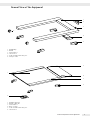 3
3
-
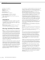 4
4
-
 5
5
-
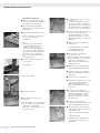 6
6
-
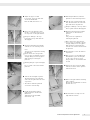 7
7
-
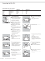 8
8
-
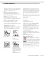 9
9
-
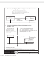 10
10
-
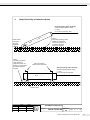 11
11
-
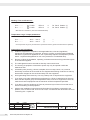 12
12
-
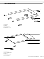 13
13
-
 14
14
-
 15
15
-
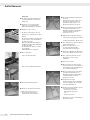 16
16
-
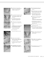 17
17
-
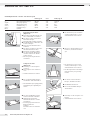 18
18
-
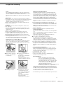 19
19
-
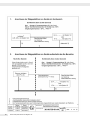 20
20
-
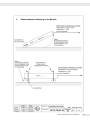 21
21
-
 22
22
-
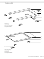 23
23
-
 24
24
-
 25
25
-
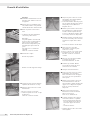 26
26
-
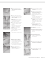 27
27
-
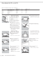 28
28
-
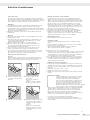 29
29
-
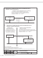 30
30
-
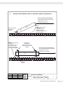 31
31
-
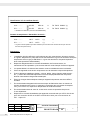 32
32
-
 33
33
-
 34
34
-
 35
35
-
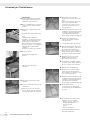 36
36
-
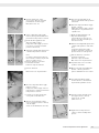 37
37
-
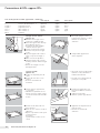 38
38
-
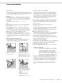 39
39
-
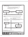 40
40
-
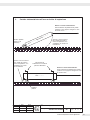 41
41
-
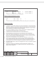 42
42
-
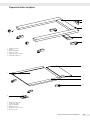 43
43
-
 44
44
-
 45
45
-
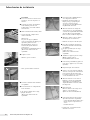 46
46
-
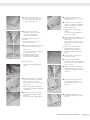 47
47
-
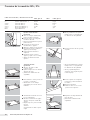 48
48
-
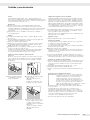 49
49
-
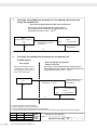 50
50
-
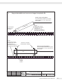 51
51
-
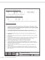 52
52
-
 53
53
-
 54
54
-
 55
55
-
 56
56
-
 57
57
-
 58
58
-
 59
59
-
 60
60


Minebea Intec Pallet Scale/Flat-bed Scale: Option Y2 for Use in Zone 2 and 22 Hazardous Areas Bedienungsanleitung
- Typ
- Bedienungsanleitung
in anderen Sprachen
- English: Minebea Intec Pallet Scale/Flat-bed Scale: Option Y2 for Use in Zone 2 and 22 Hazardous Areas Owner's manual
- français: Minebea Intec Pallet Scale/Flat-bed Scale: Option Y2 for Use in Zone 2 and 22 Hazardous Areas Le manuel du propriétaire
- español: Minebea Intec Pallet Scale/Flat-bed Scale: Option Y2 for Use in Zone 2 and 22 Hazardous Areas El manual del propietario
Verwandte Artikel
-
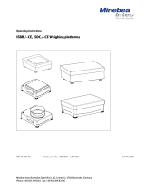 Minebea Intec ISBBS | ISBBP | ISDCS | ISDCP | ISBBS-CE | ISBBP-CE | ISDCS-CE | ISDCP-CE Weighing platforms Bedienungsanleitung
-
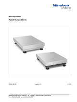 Minebea Intec Puro® Tischplattform Bedienungsanleitung
-
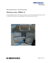 Minebea Intec YRB02-X Ex Rechargeable Battery Pack Bedienungsanleitung
-
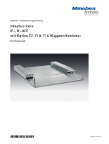 Minebea Intec IF-, IF-0CE Bedienungsanleitung
-
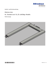 Minebea Intec IU... Palettenwaage Bedienungsanleitung
-
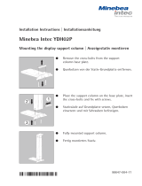 Minebea Intec Mounting the display support column Bedienungsanleitung
-
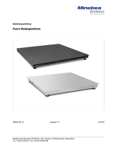 Minebea Intec Puro® Bodenplattform Bedienungsanleitung
-
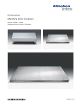 Minebea Intec Combics CAAPP.., CAAPS.. Wägeplattformen Bedienungsanleitung
-
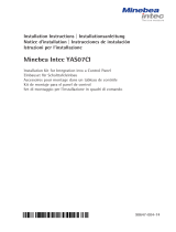 Minebea Intec Installation Kit for Integration into a Control Panel Bedienungsanleitung
-
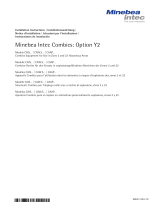 Minebea Intec Combics Option Y2 Models CAIS… | CAW.S… | CAAP… Combics Equipment for Use in Zone 2 and 22 Hazardous Areas Bedienungsanleitung


