Pepperl+Fuchs SB4 Module 4M/165 Bedienungsanleitung
- Typ
- Bedienungsanleitung

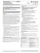
alle Maße in mm
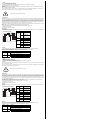
Electrical connection
Elektrischer Anschluss
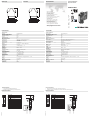
Technische Daten
Technical data
Abmessungen
Dimensions
Adressen/Addresses
Sicherheitshinweise:
•Vor der Inbetriebnahme Betriebsanleitung lesen
• Anschluss, Montage und Einstellung nur durch Fachpersonal
Security Instructions:
• Read the operating instructions before attempting commissioning
• Installation, connection and adjustments should only be undertaken by specialist personnel
all dimensions in mm
www.pepperl-fuchs.com
Pepperl+Fuchs Group
68301 Mannheim · Germany
Tel. +49 621 776-4411
Fax +49 621 776-27-4411
E-mail: fa-inf[email protected]
Worldwide Headquarters
Pepperl+Fuchs Group · Mannheim · Germany
E-mail: fa-inf[email protected]
USA Headquarters
Pepperl+Fuchs Inc. · Twinsburg · USA
E-mail: fa-inf[email protected]
Asia Pacific Headquarters
Pepperl+Fuchs Pte Ltd · Singapore
E-mail: fa-inf[email protected]
Company Registration No. 199003130E
Klemme Funktion
1 24 V Sensorversorgung
2 Sensor 2 IN
3 Sensor 4 IN
4 0 V Sensorversorgung
5 24 V Sensorversorgung
6 Sensor 1 IN
7 Sensor 3 IN
8 0 V Sensorversorgung
9 Eingang Override 1
10 24 V Override 1
11 24 V Override 2
12 Eingang Override 2
13 +24 V DC Versorgungsspannung für Mutinglampen
14 0 V DC Versorgungsspannung für Mutinglampen
15 Ausgang Mutinglampe 1
16 Ausgang Mutinglampe 2
Mutingsensor 3
Mutingsensor 1
Mutingsensor 4
Mutingsensor 2 Override 1
Override 2 Muting-
lampe 2
Muting-
lampe 1
I1
I2
M1
I3
I4
M2
13 14 15 16
9 10 11 12
1 2 3 4
5 6 7 8
I1
I2
M1
I3
I4
M2
- U
+ U
13 14 15 16
9 10 11 12
1 2 3 4
5 6 7 8
Sicherheitsschaltgerät Modul
Safety control unit module
SB4 Module 4M/165
Allgemeine Daten
Betriebsart Mutingbetriebsarten
Kenndaten funktionale Sicherheit
Sicherheits-Integritätslevel (SIL) SIL 3
Performance Level (PL) PL e
Kategorie Kat. 4
Gebrauchsdauer (TM) 20 a
Typ 4
Anzeigen/Bedienelemente
Funktionsanzeige LED gelb (4x): Leuchtmelder Mutingsensor 1 ... 4
LED weiß (2x): Status Mutinglampe
Bedienelemente DIP-Schalter
Elektrische Daten
Betriebsspannung UB24 V DC ± 20 % ,
24 V DC ± 20 % , erfolgt über SB4 Housing
Eingang
Betätigungsstrom ca. 10 mA
Betätigungszeit Override-Eingang 0,4 ... 1,2 s
Ausgang
Schaltspannung 24 V
Schaltstrom 7,5 mA ... 500 mA
Konformität
Funktionale Sicherheit ISO 13849-1 ; EN 61508 part1-4
Produktnorm EN 61496-1
Umgebungsbedingungen
Umgebungstemperatur 0 ... 50 °C (32 ... 122 °F)
Lagertemperatur -20 ... 70 °C (-4 ... 158 °F)
Schockfestigkeit siehe Betriebsanleitung
Vibrationsfestigkeit siehe Betriebsanleitung
Mechanische Daten
Schutzart IP20
Anschluss Federzugklemmen , Leitungsquerschnitt 0,2 ... 1,5 mm2
Material
Gehäuse Polyamid (PA)
Masse ca. 150 g
Zulassungen und Zertifikate
CE-Konformität CE
UL-Zulassung cULus
TÜV-Zulassung TÜV
Terminal
Function
1 24 V sensor supply
2 Sensor 2 IN
3 Sensor 4 IN
4 0 V sensor supply
5 24 V sensor supply
6 Sensor 1 IN
7 Sensor 3 IN
8 0 V sensor supply
9 Input override 1
10 24 V override 1
11 24 V override 2
12 Input override 2
13 +24 V DC supply voltage for muting lamps
14 0 V DC supply voltage for muting lamps
15 Output muting lamp 1
16 Output muting lamp 2
Override 1
Override 2 Muting
lamp 2
Muting
lamp 1
Muting sensor 3
Muting sensor 1
Muting sensor 4
Muting sensor 2
I1
I2
M1
I3
I4
M2
13 14 15 16
9 10 11 12
1 2 3 4
5 6 7 8
I1
I2
M1
I3
I4
M2
- U
+ U
13 14 15 16
9 10 11 12
1 2 3 4
5 6 7 8
06/01/2023
Date:
100,522,6
80,3
99
13 14 15 16
9 10 11 12
1 2 3 4
5 6 7 8
General specifications
Operating mode muting operating modes
Functional safety related parameters
Safety Integrity Level (SIL) SIL 3
Performance level (PL) PL e
Category Cat. 4
Mission Time (TM) 20 a
Type 4
Indicators/operating means
Function indicator LED yellow (4x): indicator lamp muting sensor 1 ... 4
LED white (2x): status muting lamp
Control elements DIP-switch
Electrical specifications
Operating voltage UB24 V DC ± 20 % ,
24 V DC ± 20 % , via SB4 Housing
Input
Activation current approx. 10 mA
Activation time Override-Input 0.4 ... 1.2 s
Output
Switching voltage 24 V
Switching current 7.5 mA ... 500 mA
Conformity
Functional safety ISO 13849-1 ; EN 61508 part1-4
Product standard EN 61496-1
Ambient conditions
Ambient temperature 0 ... 50 °C (32 ... 122 °F)
Storage temperature -20 ... 70 °C (-4 ... 158 °F)
Shock resistance see instruction manuals
Vibration resistance see instruction manuals
Mechanical specifications
Degree of protection IP20
Connection Cage tension spring terminals , Cable cross-section 0.2 ... 1.5 mm2
Material
Housing Polyamide (PA)
Mass approx. 150 g
Approvals and certificates
CE conformity CE
UL approval cULus
TÜV approval TÜV
100.522.6
80.3
99
13 14 15 16
9 10 11 12
1 2 3 4
5 6 7 8
DIN A3 -> A7
Part. 206762 45-2461G
Doc.
Safety
tested
Production
monitored
Functional
Safety

Funktionsbeschreibung
Der Betrieb dieses Moduls ist nur innerhalb eines Auswertegerätes vom Typ SafeBox SB4 möglich.
Die Betriebsanleitung der SafeBox ist zu beachten.
Funktion
Das Muting-Modul realisiert die Muting-Funktion für die Sensorkanäle des unmittelbar links neben dem Modul steckenden 4-
oder 6-kanaligen Sensorkarten-Moduls.
Der Anwender hat darauf zu achten, dass er an die Sensorkarte, die dem Muting-Modul zugeordnet ist, nur Sensoren an-
schließt, die gemutet werden dürfen. Dies sind beispielsweise Lichtschranken oder Lichtgitter
Mutingsensoren
Mutingsensoren sollen die mutenden Objekte detektieren. Wird ein Objekt detektiert, schaltet der Ausgang des Mutingsensors
seine Versorgungsspannung durch. Dazu eignen sich Sensoren mit Relais- oder pnp-Ausgang. Im spannungslosen Zustand
darf der Ausgang des Mutingsensors nicht aktiv sein. Der Sensorausgang sollte in der Lage sein, bei 20 V einen Laststrom von
8 mA zuverlässig zu schalten. Mutingsensoren, die eine Stromaufnahme von max. 30 mA haben, können direkt aus dem Mu-
ting-Modul versorgt werden. Sensoren mit größerer Stromaufnahme sind extern zu versorgen. Mutingsensoren sind so auszu-
wählen, dass sie auch bei einer Versorgungsspannung von mindestens 12 V funktionieren.
Die Leitungen zu den Mutingsensoren sind so zu verlegen, dass keine Kurzschlüsse zwischen den Mutingsensoren möglich
sind.
Als Mutingsensoren können beispielsweise folgende Sensoren eingesetzt werden:
• Reflexionslichtschranken dunkelschaltend oder hellschaltend (dann Reflektor am Objekt),
• Lichttaster (hellschaltend),
• Induktivtaster, mechanische Schalter.
Einstellungen
Auf der Baugruppe befinden sich 8 DIP-Schalter zur Auswahl der verschiedenen Muting-Betriebsarten. Zur Funktionswahl sind
immer 2 Schalter zu betätigen.
Anzeigen
Das Mutingmodul hat je Mutingsensor eine gelbe Anzeige. Für jede Mutinglampe gibt es eine weisse Anzeige.
Besteht ein Fehler im Muting-Modul, so blinken nur die gelben Anzeigen auf dieser Baugruppe.
Bei einem Fehler an den Mutinglampen blinken die weissen Mutinganzeigen.
Function description
The operation of this module is possible only within a control unit of the type SafeBox SB4.
Is the operating instruction of the SafeBox pay attention.
Function
The muting module realises the muting function for the sensor channels of the four to six channel sensor card module immedi-
ately to the right of the module.
The user must make sure to only connect sensors that can be muted to the sensor card that is assigned to the muting module.
These are, for example, light barriers or light grids
Muting sensors
Muting sensors are supposed to detect the muting objects. If an object is detected, the output of the muting sensor switches
through its supply voltage. For this purpose, sensors with relay or pnp output are suitable. In a de-energised state, the output
of the muting sensor must not be active. The sensor output should be capable of reliably switching a load current of 8 mA at 20
V. Muting sensors with a current consumption of a maximum of 30 mA can be supplied directly from the muting module. Sensors
with a higher current consumption require an external power supply. Muting sensors must be selected such that they also work
at a supply voltage of at least 12 V.
The cables to the muting sensors must be laid in such a way that no short circuits are possible between the muting sensors.
As muting sensors, the following sensors can be used, for example:
• Retro-reflective sensors dark on or light on (in this case reflector at the object)
• Photoelectric sensors (light on),
• Inductive sensors, mechanical switches.
Settings
There are 8 DIP switches on this assembly to select various muting operation types. For function selection always operate 2
switches.
Displays
The muting module has a yellow display for each muting sensor. For each muting lamp there is a white display.
If there is an error in the muting module, only the yellow displays on this assembly are flashing.
In the case of an error on the muting lamps, the white muting displays are flashing.
Not-Aus Taster dürfen nicht gemutet werden.
Schalter Position Betriebsart
1
Grup-
pe1 und
2
OFF Mutinglampen-
überwachung
inaktiv
ON Mutinglampen-
überwachung
aktiv
2
Gruppe
1 und 2
OFF einfaches Muting
ON Doppelmuting
3
Gruppe
1 und 2
OFF zeitfensterbe-
grenztes Muting
ON schutzstrahlbe-
grenztes Muting
4
Gruppe
1 und 2
OFF sequentielles
Muting
ON paralleles Muting
Anzeige LED Bedeutung
I1 - I4 gelb Dauerlicht: Mutingsensor aktiviert
Blinkend (5 Hz). Fehler Mutingsensor
M1, M2 weiß Dauerlicht: Muting aktiviert
Blinkend (5 Hz). Fehler Mutinglampe
Emergency off push buttons must not be muted.
Switch Posi-
tion
Operation type
1
Group
1 and 2
OFF Muting lamp moni-
toring inactive
ON Muting lamp moni-
toring active
2
Group
1 and 2
OFF Single muting
ON Double muting
3
Group
1 and 2
OFF Time window-lim-
ited muting
ON Protection beam-
limited muting
4
Group
1 and 2
OFF Sequential muting
ON Parallel muting
Display LED Meaning
I1 - I4 yellow Continuous light: muting sensor activated
Flashing (5 Hz). Muting sensor error
M1, M2 white Continuous light: muting activated
Flashing (5 Hz). Muting lamp error
Gefahr!
Lage der DIP-Schalter
Funktion
Gruppe 1
Funktion
Gruppe 2
ON OFF
12341234
Danger!
Position of the DIP switches
Function
group 1
Function
group 2
ON OFF
12341234
-
 1
1
-
 2
2


Pepperl+Fuchs SB4 Module 4M/165 Bedienungsanleitung
- Typ
- Bedienungsanleitung
in anderen Sprachen
Verwandte Artikel
-
Pepperl+Fuchs SB4 Module 4MD/165 Bedienungsanleitung
-
-
-
-
-
-
-
-
Andere Dokumente
-
schmersal PROTECT-SELECT-CC Bedienungsanleitung
-
 Allen-Bradley Guard Master MSR22LM Operating Instructions Manual
-
SICK MSM Muting Expansion Mudule for MSL Bedienungsanleitung
-
Schneider Electric XPSMC16 / XPSMC32 Safety controler Bedienungsanleitung
-
Leuze MSI-MD-FB Bedienungsanleitung
-
-
CARLO GAVAZZI SB4315915D25 Installationsanleitung
-
ABB Orion3 Extended Excerpts From The Original Instructions
-
