Pepperl+Fuchs SB4 Module 4CO Bedienungsanleitung
- Typ
- Bedienungsanleitung

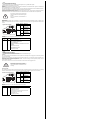
alle Maße in mm
Electrical connection
Elektrischer Anschluss
Technische Daten
Technical data
Abmessungen
Dimensions
Adressen/Addresses
Sicherheitshinweise:
•Vor der Inbetriebnahme Betriebsanleitung lesen
• Anschluss, Montage und Einstellung nur durch Fachpersonal
Security Instructions:
• Read the operating instructions before attempting commissioning
• Installation, connection and adjustments should only be undertaken by specialist personnel
all dimensions in mm
www.pepperl-fuchs.com
Pepperl+Fuchs Group
68301 Mannheim · Germany
Tel. +49 621 776-4411
Fax +49 621 776-27-4411
E-mail: fa-inf[email protected]
Worldwide Headquarters
Pepperl+Fuchs Group · Mannheim · Germany
E-mail: fa-inf[email protected]
USA Headquarters
Pepperl+Fuchs Inc. · Twinsburg · USA
E-mail: fa-inf[email protected]
Asia Pacific Headquarters
Pepperl+Fuchs Pte Ltd · Singapore
E-mail: fa-inf[email protected]
Company Registration No. 199003130E
Klemme Funktion Kanalzuordnung
1 Empfänger 2 Eingang Eingang
2 Empfänger 2 +U Kanal 2
3 Sender 2 +U
4 Sender 2 Ausgang Ausgang
5 Empfänger 1 Eingang Eingang
6 Empfänger 1 +U Kanal 1
7 Sender 1 +U
8 Sender 1 Ausgang Ausgang
9 Sender 3 Ausgang Ausgang
10 Sender 3 +U Kanal 3
11 Empfänger 3 +U
12 Empfänger 3 Eingang Eingang
13 Sender 4 Ausgang Ausgang
14 Sender 4 +U Kanal 4
15 Empfänger 4 +U
16 Empfänger 4 Eingang Eingang
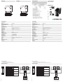
Anschlussbeispiel
(LSS = Lichtschrankensender;
LSE = Lichtschrankenempfänger)
BK
BU
LSS
BN
BU
3
4
LSS
3
1
LSE
R4
R3
R2
R1
13 14 15 16
1 2 3 4
5 6 7 8
9 10 11 12
LSE
R4
R3
R2
R1
13 14 15 16
9 10 11 12
1 2 3 4
5 6 7 8
Sicherheitsschaltgerät Modul
Safety control unit module
SB4 Module 4CO
Allgemeine Daten
Betriebsart ODER-Funktion
Kenndaten funktionale Sicherheit
Sicherheits-Integritätslevel (SIL) SIL 3
Performance Level (PL) PL e
Kategorie Kat. 4
Gebrauchsdauer (TM) 20 a
Typ 4
Anzeigen/Bedienelemente
Funktionsanzeige LED gelb (4x): Leuchtmelder Kanal 1 ... 4
Vorausfallanzeige LED gelb blinkend: Leuchtmelder Kanal 1 ... 4
Bedienelemente DIP-Schalter
Elektrische Daten
Betriebsspannung UB24 V DC ± 20 % , erfolgt über SB4 Housing
Eingang
Betätigungsstrom ca. 7 mA
Konformität
Funktionale Sicherheit ISO 13849-1 ; EN 61508 part1-4
Produktnorm EN 61496-1
Umgebungsbedingungen
Umgebungstemperatur 0 ... 50 °C (32 ... 122 °F)
Lagertemperatur -20 ... 70 °C (-4 ... 158 °F)
Schockfestigkeit siehe Betriebsanleitung
Vibrationsfestigkeit siehe Betriebsanleitung
Mechanische Daten
Schutzart IP20
Anschluss Schraubklemmen , Leitungsquerschnitt 0,2 ... 2 mm2
Material
Gehäuse Polyamid (PA)
Masse ca. 150 g
Zulassungen und Zertifikate
CE-Konformität CE
UL-Zulassung cULus
TÜV-Zulassung TÜV
Terminal
Function Channel assignment
1 Receiver 2 input Input
2 Receiver 2 +U Channel 2
3 Transmitter 2 +U
4 Transmitter 2 output Output
5 Receiver 1 input Input
6 Receiver 1 +U Channel 1
7 Transmitter 1 +U
8 Transmitter 1 output Output
9 Transmitter 3 output Output
10 Transmitter 3 +U Channel 3
11 Receiver 3 +U
12 Receiver 3 input Input
13 Transmitter 4 output Output
14 Transmitter 4 +U Channel 4
15 Receiver 4 +U
16 Receiver 4 input Input
Connection example
(LSS = transmitter of light barrier;
LSE = receiver of light barrier)
BK
BU
LSS
BN
BU
3
4
LSS
3
1
LSE
R4
R3
R2
R1
13 14 15 16
1 2 3 4
5 6 7 8
9 10 11 12
LSE
R4
R3
R2
R1
13 14 15 16
9 10 11 12
1 2 3 4
5 6 7 8
05/31/2023
Date:
100,522,6
80,3
99
13 14 15 16
9 10 11 12
1 2 3 4
5 6 7 8
General specifications
Operating mode ODER-Function
Functional safety related parameters
Safety Integrity Level (SIL) SIL 3
Performance level (PL) PL e
Category Cat. 4
Mission Time (TM) 20 a
Type 4
Indicators/operating means
Function indicator LED yellow (4x): indicator lamp channel 1 ... 4
Pre-fault indicator LED yellow flashing: Indicator lamp channel 1 ... 4
Control elements DIP-switch
Electrical specifications
Operating voltage UB24 V DC ± 20 % , via SB4 Housing
Input
Activation current approx. 7 mA
Conformity
Functional safety ISO 13849-1 ; EN 61508 part1-4
Product standard EN 61496-1
Ambient conditions
Ambient temperature 0 ... 50 °C (32 ... 122 °F)
Storage temperature -20 ... 70 °C (-4 ... 158 °F)
Shock resistance see instruction manuals
Vibration resistance see instruction manuals
Mechanical specifications
Degree of protection IP20
Connection screw terminals , lead cross section 0.2 ... 2 mm2
Material
Housing Polyamide (PA)
Mass approx. 150 g
Approvals and certificates
CE conformity CE
UL approval cULus
TÜV approval TÜV
100.522.6
80.3
99
13 14 15 16
9 10 11 12
1 2 3 4
5 6 7 8
DIN A3 -> A7
Part. 182115 45-1415J
Doc.
Safety
tested
Production
monitored
Functional
Safety

Funktionsbeschreibung
Der Betrieb dieses Moduls ist nur innerhalb eines Auswertegerätes vom Typ SafeBox SB4 möglich.
Die Betriebsanleitung der SafeBox ist zu beachten.
Funktion
Das 4-kanalige Sensorkarten-Modul SB4-4CO ermöglicht den Anschluss von Lichtschranken oder -gittern bzw. kontaktbehaf-
teten Sicherheitssensoren in einkanaliger Ausführung.
Beim Einschalten des Systems ermittelt die Software, ob an einem Kanal eine Lichtschranke oder ein kontaktbehafteter Sicher-
heitssensor angeschaltet ist und überwacht während des Betriebes seine Anwesenheit.
Kontaktbehaftete Sicherheitssensoren, die an die Safebox angeschlossen werden, müssen nach dem Öffnerprinzip arbeiten.
Ein offener Kontakt bedeutet "sicherer Zustand".
Die Kanäle1 und 2 sowie 3 und 4 können beim Einsatz von Lichtschranken über eine ODER-Funktion verknüpft werden.
Betriebsarten
Auf der Baugruppe befinden sich 4 DIP-Schalter zur Auswahl ODER-Verknüpfung benachbarter Kanäle (1 ODER 2 und 3
ODER 4). Zur Funktionswahl sind immer 2 Schalter zu betätigen. Die Funktionen sind nur bei angeschlossenen Lichtschranken
wirksam
Anzeigen
Je Kanal gibt es auf der Frontplatte des Moduls eine gelbe LED..
Function description
This module can only be operated within an evaluation device of the SafeBox SB4 type.
The SafeBox instruction manual should be observed.
Function
The 4-channel sensor card module SB4-4CO makes it possible to connect light barriers or light grids or contact safety sensors
in a one-channel version.
When the system is switched on, the software determines whether a light barrier or a contact safety sensor is switched on at a
channel and monitors its presence during operation.
Contact safety sensors, which are connected to the SafeBox, must work according to the normally closed principle. An open
contact indicates "safe state".
The channels 1 and 2 as well as 3 and 4 can be combined via an OR function when using light barriers.
Operating modes
The assembly has 4 DIP switches for selecting the OR-operation of neighbouring channels (1 OR 2 and 3 OR 4). For selecting
functions, 2 selector switches must always be actuated. The functions are only effective if light barriers are connected.
Displays
For each channel, there is a yellow LED on the front panel of the module..
Es ist darauf zu achten, dass bei Nutzung dieser
Funktion die Wirksamkeit der Absicherung erhal-
ten bleibt.
Dies ist bei Installation und Inbetriebnahme zu
überprüfen.
Schalter Position Betriebsart
1 und 3 OFF keine ODER-
Verknüpfung
Kanal 1 und 2
ON ODER-Verknüp-
fung Kanal 1 und
2
2 und 4 OFF keine ODER-
Verknüpfung
Kanal 3 und 4
ON ODER-Verknüp-
fung Kanal 3 und
4
Anzeige LED Bedeutung
R1 - R4 gelb Status Lichtschranke 1 ... 4
Aus: Lichtstrahl unterbrochen
Ein: Lichtstrahl frei
Blinkend: Lichtstrahl frei, Funktionsreserve unter-
schritten
(Frequenz ca. 2,5 Hz)
Schnell blinkend: Fehler
(Frequenz ca. 5 Hz)
When using this function, it must be ensured that
the effectiveness of the fusing is maintained.
This must be checked on installation and com-
missioning .
Switch Position Operation type
1 and 3 OFF No OR-opera-
tion channel 1
and 2
ON OR-operation
channel 1 and 2
2 and 4 OFF No OR-opera-
tion channel 3
and 4
ON OR-operation
channel 3 and 4
Display LED Meaning
R1 - R4 yellow Status of light barrier 1 ... 4
Off: light beam interrupted
On: light beam released
Flashing: light beam released, function reserve fallen
short of (frequency approx. 2.5 Hz)
Flashing fast: error
(frequency approx. 5 Hz)
Gefahr!
Lage der DIP-Schalter
ON
OFF
4 3 2 1
Danger!
Position of the DIP switches
ON
OFF
4 3 2 1
-
 1
1
-
 2
2


Pepperl+Fuchs SB4 Module 4CO Bedienungsanleitung
- Typ
- Bedienungsanleitung
in anderen Sprachen
Verwandte Artikel
-
Pepperl+Fuchs SB4 Module 4COP Bedienungsanleitung
-
-
-
-
-
-
-
-
-