Pepperl+Fuchs SB4 Module 4XP Bedienungsanleitung
- Typ
- Bedienungsanleitung

alle Maße in mm
Electrical connection
Elektrischer Anschluss
Technische Daten
Technical data
Abmessungen
Dimensions
Adressen/Addresses
Sicherheitshinweise:
•Vor der Inbetriebnahme Betriebsanleitung lesen
• Anschluss, Montage und Einstellung nur durch Fachpersonal
Security Instructions:
• Read the operating instructions before attempting commissioning
• Installation, connection and adjustments should only be undertaken by specialist personnel
all dimensions in mm
www.pepperl-fuchs.com
Pepperl+Fuchs Group
68301 Mannheim · Germany
Tel. +49 621 776-4411
Fax +49 621 776-27-4411
E-mail: fa-inf[email protected]
Worldwide Headquarters
Pepperl+Fuchs Group · Mannheim · Germany
E-mail: fa-inf[email protected]
USA Headquarters
Pepperl+Fuchs Inc. · Twinsburg · USA
E-mail: fa-inf[email protected]
Asia Pacific Headquarters
Pepperl+Fuchs Pte Ltd · Singapore
E-mail: fa-inf[email protected]
Company Registration No. 199003130E
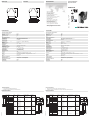
Klemme Funktion Kanal- Anschluss Anschluss 2-kanalig Anschluss
zuordnung Lichtschranke / Lichtgitter p-schaltend Schaltmatte
Sicherheitseinrichtung
1 Empfänger 2 Eingang Eingang Empfängerausgang 2 OSSD-Ausgang 1.2 Schaltmatte 1.4
2 Sensor 2 24 V DC +U Kanal 2 24 V Empfänger 2 24 V Versorgung 1
3 Sensor 2 Masse GND 0 V Empfänger 2, 0 V Versorgung 1
Sender 2
4 Sender 2 Ausgang Ausgang Sendereingang 2 Schaltmatte 1.3
5 Empfänger 1 Eingang Eingang Empfängerausgang 1 OSSD-Ausgang 1.1 Schaltmatte 1.2
6 Sensor 1 24 V DC +U Kanal 1 24 V Empfänger 1
7 Sensor 1 Masse GND 0 V Empfänger 1,
Sender 1
8 Sender 1 Ausgang Ausgang Sendereingang 1 Schaltmatte 1.1
9 Sender 3 Ausgang Ausgang Sendereingang 3 Schaltmatte 2.4
10 Sensor 3 Masse GND Kanal 3 0 V Empfänger 3, 0 V Versorgungsspannung 2
Sender 3
11 Sensor 3 24 V DC +U 24 V Empfänger 3 24 V Versorgungsspannung 2
12 Empfänger 3 Eingang Eingang Empfängerausgang 3 OSSD Ausgang 2.2 Schaltmatte 2.3
13 Sender 4 Ausgang Ausgang Sendereingang 2 Schaltmatte 2.2
14 Sensor 4 Masse GND Kanal 4 0 V Empfänger 4,
Sender 4
15 Sensor 4 24 V DC +U 24 V Empfänger 4
16 Empfänger 4 Eingang Eingang Empfängerausgang 4 OSSD Ausgang 2.1 Schaltmatte 2.1
R4
R3
R2
R1
13 14 15 16
9 10 11 12
1 2 3 4
5 6 7 8
BU
BK
BU
BN
BK
LSS
4
3LSS
LSE
4
1
3
LSE
13 14 15 16
9 10 11 12
1 2 3 4
5 6 7 8
Sicherheitsschaltgerät Modul
Safety control unit module
SB4 Module 4XP
Kenndaten funktionale Sicherheit
Sicherheits-Integritätslevel (SIL) SIL 3
Performance Level (PL) PL e
Kategorie Kat. 4
Gebrauchsdauer (TM) 20 a
Typ 4
Anzeigen/Bedienelemente
Funktionsanzeige LED gelb (4x): Leuchtmelder Kanal 1 ... 4
Vorausfallanzeige LED gelb blinkend: Leuchtmelder Kanal 1 ... 4
Bedienelemente DIP-Schalter
Elektrische Daten
Betriebsspannung UB24 V DC ± 20 % , erfolgt über SB4 Housing
Eingang
Betätigungsspannung ca. 10 V
Betätigungsstrom ca. 4 ... 20 mA
Konformität
Funktionale Sicherheit ISO 13849-1 ; EN 61508 part1-4
Produktnorm EN 61496-1
Umgebungsbedingungen
Umgebungstemperatur 0 ... 50 °C (32 ... 122 °F)
Lagertemperatur -20 ... 70 °C (-4 ... 158 °F)
Schockfestigkeit siehe Betriebsanleitung
Vibrationsfestigkeit siehe Betriebsanleitung
Mechanische Daten
Schutzart IP20
Anschluss Schraubklemmen , Leitungsquerschnitt 0,2 ... 2 mm2
Option /165: Federzugklemmen , Leitungsquerschnitt 0,2 ... 1,5 mm2
Material
Gehäuse Polyamid (PA)
Masse ca. 150 g
Allgemeine Informationen
Bestellinformationen ohne Option /165 -> mit Schraubklemmen
mit Option /165 -> mit Federzugklemmen
Zulassungen und Zertifikate
CE-Konformität CE
UL-Zulassung cULus
TÜV-Zulassung TÜV
Terminal Function Channel Connection Connection 2-channel Connection
classification Beam sensor / Light grid p ON Switching pad
safety feature
1 Receiver 2 Input Input Receiver output 2 OSSD Output 1.2 Switching pad 1.4
2 Sensor 2 24 V DC +U Channel 2 24 V Receiver2 24 V Power supply 1
3 Sensor 2 Mass GND 0 V Receiver 2, 0 V Power supply 1
Emitter 2
4 Emitter 2 Output Output Emitter input 2 Switching pad 1.3
5 Receiver 1 Input Input Receiver output 1 OSSD Output 1.1 Switching pad 1.2
6 Sensor 1 24 V DC +U Channel 1 24 V Receiver 1
7 Sensor 1 Mass GND 0 V Receiver 1,
Emitter 1
8 Emitter 1 Output Output Emitter input 1 Switching pad 1.1
9 Emitter 3 Output Output Emitter input 3 Switching pad 2.4
10 Sensor 3 Mass GND Channel 3 0 V Receiver 3, 0 V Power supply 2
Emitter 3
11 Sensor 3 24 V DC +U 24 V Receiver 3 24 V Power supply 2
12 Receiver 3 Input Input Receiver output 3 OSSD Output 2.2 Switching pad 2.3
13 Emitter 4 Output Output Emitter input 2 Switching pad 2.2
14 Sensor 4 Mass GND Channel 4 0 V Receiver 4,
Emitter 4
15 Sensor 4 24 V DC +U 24 V Receiver 4
16 Receiver 4 Input Input Receiver output 4 OSSD Output 2.1 Switching pad 2.1
R4
R3
R2
R1
13 14 15 16
9 10 11 12
1 2 3 4
5 6 7 8
BU
BK
BU
BN
BK
LSS
4
3LSS
LSE
4
1
3
LSE
13 14 15 16
9 10 11 12
1 2 3 4
5 6 7 8
06/01/2023
Date:
100,522,6
80,3
99
13 14 15 16
9 10 11 12
1 2 3 4
5 6 7 8
Functional safety related parameters
Safety Integrity Level (SIL) SIL 3
Performance level (PL) PL e
Category Cat. 4
Mission Time (TM) 20 a
Type 4
Indicators/operating means
Function indicator LED yellow (4x): indicator lamp channel 1 ... 4
Pre-fault indicator LED yellow flashing: Indicator lamp channel 1 ... 4
Control elements DIP-switch
Electrical specifications
Operating voltage UB24 V DC ± 20 % , via SB4 Housing
Input
Actuating voltage approx. 10 V
Activation current approx. 4 ... 20 mA
Conformity
Functional safety ISO 13849-1 ; EN 61508 part1-4
Product standard EN 61496-1
Ambient conditions
Ambient temperature 0 ... 50 °C (32 ... 122 °F)
Storage temperature -20 ... 70 °C (-4 ... 158 °F)
Shock resistance see instruction manuals
Vibration resistance see instruction manuals
Mechanical specifications
Degree of protection IP20
Connection screw terminals , lead cross section 0.2 ... 2 mm2
Option /165: Cage tension spring terminals , Cable cross-section 0.2 ... 1.5 mm2
Material
Housing Polyamide (PA)
Mass approx. 150 g
General information
Ordering information without Option /165 -> with screw terminals
with Option /165 -> spring clamp terminals
Approvals and certificates
CE conformity CE
UL approval cULus
TÜV approval TÜV
100.522.6
80.3
99
13 14 15 16
9 10 11 12
1 2 3 4
5 6 7 8
DIN A3 -> A7
Part. 192145 45-1998K
Doc.
Safety
tested
Production
monitored
Functional
Safety

Der Betrieb dieses Moduls ist nur innerhalb eines Auswertegerätes vom Typ SafeBox SB4 möglich.
Die Betriebsanleitung der SafeBox ist zu beachten.
Das 4-kanalige Sensor-Modul -4X* ermöglicht den Anschluss von sogenannten "3-Draht"-Lichtschranken der Familien SLA (bei-
spielsweise SLA5) und Lichtgittern vom Typ SLP. Es können aber auch p-schaltende Sicherheitseinrichtungen mit eigener Quer-
schlussüberwachung angeschlossen werden, beispielsweise Sicherheitslichtvorhänge der SLC-Familie. Darüber hinaus lassen
sich Schaltmatten nach dem 4-Leiter-Prinzip oder kontaktbehaftete Sicherheitssensoren in ein- oder zweikanaliger Ausführung
anschließen.
Außerdem enthält es die Mikrokontroller-Steuerung der SafeBox. Dieses Modul ist nur einmal in einer SafeBox SB4 enthalten
und muss auf den Platz2 gesteckt werden.
Auf dem Modul befindet sich eine Steckbrücke. Enthält das System weitere Baugruppen, so muss diese Steckbrücke auf den
letzten Steckplatz umgesteckt werden.
Auf der Baugruppe befindet sich ein sechsfach-DIP-Schalter mit dem die anzuschließenden Sensoren ausgewählt werden. Es
müssen 2 Schalter paarweise zur Auswahl betätigt werden. Der Anschluss der Sicherheitssensoren erfolgt an den Kanälen 1 und
2 oder 3 und 4.
"3-Draht"-Lichtschranken und -gitter der Familien SLA und SLP können an den Kanälen 1 bis 4 angeschlossen werden.
Die Kabel bzw. deren Verlegung zu den Lichtschranken und -gittern sind so auszuwählen, dass ein Kurzschluss zwischen Emp-
fänger- und Senderleitung nicht möglich ist.
Lichtvorhänge mit Halbleiter-Schaltausgängen und kontaktbehaftete Sicherheitssensoren in zweikanaliger Ausführung werden
auf Gleichzeitigkeit überwacht. Bei der Gleichzeitigkeitsüberwachung werden die Sicherheitseinrichtungen auf gleichzeitiges
Öffnen bzw. Wechseln der Signale überwacht. Die Überwachungszeit beträgt 2 s.
Der Anschluss erfolgt an den Kanälen 3 und 4 und/oder 1 und 2.
Es ist zu beachten, dass diese Sensoren eine eigene Querschlussüberwachung aufweisen müssen, da das Modul bei diesen
Sensoren die Querschlussüberwachung nicht ausführt.
Kontaktbehaftete Sicherheitssensoren, die an die SafeBox angeschlossen werden, müssen nach dem Öffnerprinzip arbeiten.
Ein offener Kontakt bedeutet "sicherer Zustand".
Schaltmatten nach dem 4-Leiter-Prinzip können an den Kanälen 1 und 2 und/oder 3 und 4 angeschlossen werden. Liegt eine
fehlerhafte Kontaktierung der Schaltmatte vor, so meldet das System den Fehler 9 bzw. Fehler 8 wie bei Detektion eines kontakt-
behaftete Sicherheitssensors in zweikanaliger Ausführung.
Auf der Baugruppe befinden sich 6 DIP-Schalter zur Auswahl des Sensortyps und der Position. Es werden sechs Möglichkeiten
angeboten, Sensoren zu kombinieren. Die gewünschte Kombination ist binär einzustellen. Zur Funktionswahl sind immer 2
Schalter zu betätigen, dass heißt, DIP-Schalter 1...3 haben die gleiche Schaltstellung wie DIP-Schalter 4...6.
Je Kanal gibt es auf der Frontplatte des Moduls eine gelbe LED, die den Status des Eingangskanals anzeigt.
Die Anschlüsse sind als abziehbare Schraubklemmen ausgeführt. Die Klemmenbelegung ist aus der nebenstehenden Tabelle
zu entnehmen.
An das 4-kanalige Sensor-Modul können bis zu 4 Lichtschranken oder 2 zweikanalige p-schaltende Sicherheitseinrichtungen
oder 2 Schaltmatten angeschlossen werden. Unbenutzte Kanäle sind durch eine Brücke zwischen Senderausgang und Empfän-
gereingang unwirksam zu machen.
This module can only be operated within an evaluation device of the SafeBox SB4 type.
The operating instructions of the SafeBox must be observed.
The 4-channel sensor module -4X* makes possible the connection of the so-called "3-wire" light barriers of the SLA family (for
example SLA5) and light grids of type SLP. But also p-switching safety devices with dedicated cross circuit monitoring can be
connected, for example safety light curtains from the SLC family. In addition switch-off mats of the 4-wire principle or integrated
safety sensors in the 1 or 2 channel version can be connected.
It also contains the microcontroller control of the SafeBox. This module exists only once in a SafeBox SB4 and has to be mounted
on position 2.
The module is equipped with a plug-in jumper. If the system features additional components, this plug-in jumper has to be moun-
ted on the last mounting station.
In the assembly is also found a six-way DIP switch with which the sensors to be connected are selected. 2 switches must be ac-
tivated as a pair for selection. The connection of the safety sensors is done on channels 1 and 2 or 3 and 4.
"3-wire" light barriers and light grids of the SLA and SLP families can be connected to channels 1 to 4.
The cable or the manner it is laid to the light barriers and light grids must be chosen that no short circuit between the receiver and
transmitter wires is possible.
Light curtains with semiconductor switch outputs and integrated safety sensors in 2 channel design are monitored for simulta-
neousness. During simultaneousness monitoring the 2 channel safety devices are monitored for simultaneous opening or chan-
ging of the signals. The monitoring time is 2 s.
The connection is done on channels 3 and 4 and/or 1 and 2.
It is necessary that these sensors must have a dedicated cross circuit monitoring, since the module does not perform cross circuit
monitoring with these sensors.
Integrated safety sensors, which are connected to the Safebox must work according to the normally closed principle. An open
contact means "safe status".
Switch-off mats of the 4-wire principle can be connected to channels 1 and 2 and/or 3 and 4. If there is a faulty contact of the
switch-off mat, the system reports Error 9 or Error 8, like the detection of an integrated safety sensor in the two-channel design.
The assembly contains 6 DIP switches for selecting the sensor types and the position. Six possibilities are offered for combining
sensors. The desired combination is to be set binary. For function selection, always 2 switches must be actuated, that means DIP
switches 1 - 3 have the same switch position as DIP switches 4 - 6.
There is a yellow LED for each channel on the front plate of the module which displays the status of the input channel.
Connections are designed as removable screw terminals. The terminal assignment can be found in the adjoining table.
Up to 4 light barriers or 2 two-channel p-switching safety devices or 2 switch-off mats can be connected to the 4-channel sensor
module. Unused channels must be deactivated by means of a bridge between transmitter output and receiver input.
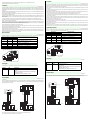
Funktion
Betriebsarten
DIP-Schalter Betriebsart
3 und 6 2 und 5 1 und 4
0 0 0 SLA / SLP / Brücke Kanal 1 + 2 und Kanal 3 + 4
0 0 1 SLA / SLP / Brücke an Kanal 1 + 2 und
SLC Kanal 3 + 4
0 1 0 SLC Kanal 1 + 2 und Kanal 3 + 4
0 1 1 SLA / SLP / Brücke Kanal 1 + 2 und
Trittmatte Kanal 3 + 4
1 0 0 Trittmatte Kanal 1 + 2 und Kanal 3 + 4
1 0 1 SLC Kanal 1 + 2 und Trittmatte Kanal 3 + 4
Anzeigen
Anzeige LED Bedeutung
R1 - R4
(R1 - R6) gelb Status Sensoreingang 1 ... 4
Aus: unterbrochen
Ein: frei
Blinkend: Lichtstrahl frei, Funktionsreserve unterschritten
(Frequenz ca. 2,5 Hz)
Schnell blinkend: Fehler (Frequenz ca. 5 Hz)
Anschlüsse
Lage der DIP-Schalter
ON
OFF
4 36 5 2 1
13 14 15 16
9 10 11 12
1 2 3 4
5 6 7 8
OSSD1
OSSD2
Lichtvorhang SLC
Schaltmatte
Empfänger Sender
24 V DC
GND
24 V DC
GND
GND
24 V DC
24 V DC
GND
13 14 15 16
9 10 11 12
1 2 3 4
5 6 7 8
24 V DC
GND
24 V DC
GND
OSSD1
OSSD2
24 V DC
GND
24 V DC
GND
24 V DC
GND
GND
24 V DC
OSSD1
OSSD2
24 V DC
GND
Empfänger Sender
Lichtvorhang 2 SLC
Lichtvorhang 1 SLC
Empfänger Sender
Function
Operating modes
DIP switch Operating mode
3 and 6 2 and 5 1 and 4
0 0 0 SLA /SLP/ bridge channel 1 + 2 and channel 3 + 4
0 0 1 SLA / SLP / jumper to channel 1 + 2 and
SLC channel 3 + 4
0 1 0 SLC channel 1 + 2 and channel 3 + 4
0 1 1 SLA / SLP / jumper channel 1 + 2 and
safety mat channel 3 + 4
1 0 0 Safety mat channel 1 + 2 and channel 3 + 4
1 0 1 SLC channel 1 + 2 and safety mat channel 3 + 4
Displays
Display LED Meaning
R1 - R4
(R1 - R6) yellow Status sensor input 1 - 4
OFF: interrupted
ON: released
Flashing: light beam released, function reserve fallen short
of
(frequency approx. 2.5 Hz)
Flashing rapidly: error (frequency approx. 5 Hz)
Connections
Position of the DIP switches
ON
OFF
4 36 5 2 1
13 14 15 16
9 10 11 12
1 2 3 4
5 6 7 8
OSSD1
OSSD2
light curtain SLC
Receiver Emitter
switch-off mat
24 V DC
GND
24 V DC
GND
GND
24 V DC
24 V DC
GND
13 14 15 16
9 10 11 12
1 2 3 4
5 6 7 8
24 V DC
GND
24 V DC
GND
OSSD1
OSSD2
24 V DC
GND
24 V DC
GND
24 V DC
GND
GND
24 V DC
OSSD1
OSSD2
24 V DC
GND
Receiver Emitter
light curtain 2 SLC
light curtain 1 SLC
Receiver Emitter
-
 1
1
-
 2
2


Pepperl+Fuchs SB4 Module 4XP Bedienungsanleitung
- Typ
- Bedienungsanleitung
in anderen Sprachen
Verwandte Artikel
-
Pepperl+Fuchs SB4 Module 4X/165 Bedienungsanleitung
-
-
-
-
-
-
-
-
-