Pepperl+Fuchs SB4 Module 2E Bedienungsanleitung
- Typ
- Bedienungsanleitung

alle Maße in mm
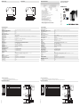
Electrical connection
Elektrischer Anschluss
Technische Daten
Technical data
Abmessungen
Dimensions
Adressen/Addresses
Sicherheitshinweise:
•Vor der Inbetriebnahme Betriebsanleitung lesen
• Anschluss, Montage und Einstellung nur durch Fachpersonal
Security Instructions:
• Read the operating instructions before attempting commissioning
• Installation, connection and adjustments should only be undertaken by specialist personnel
all dimensions in mm
www.pepperl-fuchs.com
Pepperl+Fuchs Group
68301 Mannheim · Germany
Tel. +49 621 776-4411
Fax +49 621 776-27-4411
E-mail: fa-inf[email protected]
Worldwide Headquarters
Pepperl+Fuchs Group · Mannheim · Germany
E-mail: fa-inf[email protected]
USA Headquarters
Pepperl+Fuchs Inc. · Twinsburg · USA
E-mail: fa-inf[email protected]
Asia Pacific Headquarters
Pepperl+Fuchs Pte Ltd · Singapore
E-mail: fa-inf[email protected]
Company Registration No. 199003130E
Klemme Funktion
1 Sicherheitselement 1.1 Out
2 Sicherheitselement 1.1 In
3 Sicherheitselement 1.2 Out
4 Sicherheitselement 1.2 In
5 - 6 OSSD1; potentialfreier Relaiskontakt; Schliesser
7 - 8 OSSD2; potentialfreier Relaiskontakt; Schliesser
9 Signalausgang OSSD Aus
10 Signalausgang OSSD Ein
11 Signalausgang Restart
12 Relaismonitor (RM)
13 +24 V DC Versorgungsspannung für Meldeausgänge
14 0 V DC Versorgungsspannung für Meldeausgänge
15 24 V DC Anschluss Restart und RM
16 Restart-Eingang (RI); Öffnerkontakt
Restart
Relaismonitor
gelb
grün
rot
Sicherheits-
element 1.2
Sicherheits-
element 1.1
- U
+ U
OSSD
RI
I2
I1
K2.1
K1.1
OSSD
RI
I2
I1
- U
rel
+ U
rel
F2F1
K2K1
13 14 15 16
9 10 11 12
1 2 3 4
5 6 7 8
13 14 15 16
9 10 11 12
1 2 3 4
5 6 7 8
Sicherheitsschaltgerät Modul
Safety control unit module
SB4 Module 2E
Allgemeine Daten
Betriebsart Anlauf-/Wiederanlaufsperre, Relaismonitor, Not-Aus, Abschaltzeit
Kenndaten funktionale Sicherheit
Sicherheits-Integritätslevel (SIL) SIL 3
Performance Level (PL) PL e
Kategorie Kat. 4
Gebrauchsdauer (TM) 20 a
Typ 4
Anzeigen/Bedienelemente
Funktionsanzeige LED rot: OSSD aus
LED grün: OSSD ein LED gelb: Anlaufbereitschaft LED gelb (2x): Leuchtmelder Kanal 1 ... 2
Bedienelemente DIP-Schalter
Elektrische Daten
Betriebsspannung UB24 V DC ± 20 % ,
24 V DC ± 20 % , erfolgt über SB4 Housing
Eingang
Betätigungsstrom ca. 7 mA
Testeingang Reset-Eingang für Systemtest
Ausgang
Sicherheitsausgang 2 Relaisausgänge, zwangsgeführte Schließerkontakte
Signalausgang Ausgang zur Anzeige des Schaltzustands der OSSDs
Schaltspannung 10 V ... 250 V AC/DC
Schaltstrom min. 10 mA , max. 6 A AC/DC
Schaltleistung max. DC 24 VA , AC 230 VA
Konformität
Funktionale Sicherheit ISO 13849-1 ; EN 61508 part1-4
Produktnorm EN 61496-1
Umgebungsbedingungen
Umgebungstemperatur 0 ... 50 °C (32 ... 122 °F)
Lagertemperatur -20 ... 70 °C (-4 ... 158 °F)
Schockfestigkeit siehe Betriebsanleitung
Vibrationsfestigkeit siehe Betriebsanleitung
Mechanische Daten
Schutzart IP20
Anschluss Schraubklemmen , Leitungsquerschnitt 0,2 ... 2 mm2
Option /165: Federzugklemmen , Leitungsquerschnitt 0,2 ... 1,5 mm2
Material
Gehäuse Polyamid (PA)
Masse ca. 150 g
Allgemeine Informationen
Bestellinformationen ohne Option /165 -> mit Schraubklemmen
mit Option /165 -> mit Federzugklemmen
Zulassungen und Zertifikate
CE-Konformität CE
UL-Zulassung cULus
TÜV-Zulassung TÜV
relay monitor
Restart
Terminal Function
1 Safety element 1.1 Out
2 Safety element 1.1 In
3 Safety element 1.2 Out
4 Safety element 1.2 In
5 - 6 OSSD1; potential free relay contact; normally open contact
7 - 8 OSSD2; potential free relay contact; normally open contact
9 Signal output OSSD off
10 Signal output OSSD on
11 Signal output restart
12 Relay monitor (RM)
13 +24 V DC supply voltage
14 0 V DC supply voltage
15 24 V DC connection restart and RM
16 Restart input (RI); normally closed contact
yellow
green
red
Safety
element 1.2
Safety
element 1.1
- U
+ U
OSSD
RI
I2
I1
K2.1
K1.1
OSSD
RI
I2
I1
- U
rel
+ U
rel
F2F1
K2K1
13 14 15 16
9 10 11 12
1 2 3 4
5 6 7 8
13 14 15 16
9 10 11 12
1 2 3 4
5 6 7 8
05/31/2023
Date:
100,522,6
80,3
99
13 14 15 16
9 10 11 12
1 2 3 4
5 6 7 8
General specifications
Operating mode Startup/restart disable, relay monitor, emergency off, turn off time
Functional safety related parameters
Safety Integrity Level (SIL) SIL 3
Performance level (PL) PL e
Category Cat. 4
Mission Time (TM) 20 a
Type 4
Indicators/operating means
Function indicator LED red: OSSD OFF
LED green: OSSD ON Yellow LED: start readiness LED yellow (2x): indicator lamp channel 1 ... 2
Control elements DIP-switch
Electrical specifications
Operating voltage UB24 V DC ± 20 % ,
24 V DC ± 20 % , via SB4 Housing
Input
Activation current approx. 7 mA
Test input Reset-input for system test
Output
Safety output 2 relay outputs, force-guided NO-contact
Signal output Output for displaying the switching state of the OSSDs
Switching voltage 10 V ... 250 V AC/DC
Switching current min. 10 mA , max. 6 A AC/DC
Switching power max. DC 24 VA , AC 230 VA
Conformity
Functional safety ISO 13849-1 ; EN 61508 part1-4
Product standard EN 61496-1
Ambient conditions
Ambient temperature 0 ... 50 °C (32 ... 122 °F)
Storage temperature -20 ... 70 °C (-4 ... 158 °F)
Shock resistance see instruction manuals
Vibration resistance see instruction manuals
Mechanical specifications
Degree of protection IP20
Connection screw terminals , lead cross section 0.2 ... 2 mm2
Option /165: Cage tension spring terminals , Cable cross-section 0.2 ... 1.5 mm2
Material
Housing Polyamide (PA)
Mass approx. 150 g
General information
Ordering information without Option /165 -> with screw terminals
with Option /165 -> spring clamp terminals
Approvals and certificates
CE conformity CE
UL approval cULus
TÜV approval TÜV
100.522.6
80.3
99
13 14 15 16
9 10 11 12
1 2 3 4
5 6 7 8
DIN A3 -> A7
Part. 182112 45-1408L
Doc.
Safety
tested
Production
monitored
Functional
Safety

Funktionsbeschreibung
Der Betrieb dieses Moduls ist nur innerhalb eines Auswertegerätes vom Typ SafeBox SB4 möglich.
Die Betriebsanleitung der SafeBox ist zu beachten.
Funktion
Das OSSD-R/E-Stop-Modul beinhaltet 2 OSSDs, den Relaismonitor, den Restart-Anschluss und 2 Anschlüsse für kontaktbe-
haftete Sicherheitssignale (z.B. Not-Aus-Taster). Dieses Modul kann mehrfach ab der Position 3 in der SafeBox vorhanden sein
und unterschiedliche Funktionen je nach Schalterstellung ausführen.
Die OSSDs sind als potentialfreie Schliesserkontakte ausgeführt. Das Modul kann wahlweise mit oder ohne Anlauf-/Wiederan-
laufsperre betrieben werden. Ebenso ist die Überwachung der extern angeschlossenen Schaltelemente aktivierbar (Relaismo-
nitor). Die Zustände OSSD Ein bzw. Aus werden über je einen kurzschlussfesten pnp-Meldeausgang signalisiert. Der Ausgang
Restart dient der Meldung des Zustandes Anlaufbereitschaft. Im Fehlerfall oszilliert dieser Ausgang mit 1Hz.
Sollten die Sensoreingänge des OSSD-R/E-Stop-Modul unbenutzt bleiben, so ist eine Brücke einzulegen, dies gilt auch bei ein-
gestellter Stop 1 - Funktion.
Das Modul kann in der Stop-Funktion Kat. 0 oder Kat.1 arbeiten oder in der Zentral Stop-Funktionalität Kat.0 arbeiten.
Einstellungen
Auf der Baugruppe befinden sich 16 DIP-Schalter zur Auswahl der Funktionen Restart, Relaismonitor, Zentraler Not-Aus,
OSSD-Zuordnung und Zeitfunktion. Zur Funktionswahl sind immer 2 Schalter zu betätigen..
.
Anzeigen
Die OSSD-Baugruppe hat eine rot/grüne LED zur Signalisierung der Zustände OSSD aus/ein, eine gelbe LED für den Zustand
Anlaufbereit und 2 LEDs für die Sensorkanäle.
Besteht ein Fehler auf der OSSD-Baugruppe selbst, so blinken nur die Anzeigen auf dieser Baugruppe.
Function description
This module can only be operated within an evaluation device of the SafeBox SB4 type.
The SafeBox instruction manual should be observed.
Function
The OSSD-R/E stop module contains 2 OSSDs, the relay monitor, the restart connection and 2 connections for contact safety
signals, (e.g. emergency off button). From position 3 on, this module may exist several times in the SafeBox and may perform
different functions depending on the switch position.
The OSSDs are designed as potential free connection NO contacts. The module can be operated with or without restart inter-
lock. Also, monitoring of the externally connected switching elements can be activated (relay monitor). The OSSD On or Off
statuses are indicated via a short-circuit-proof pnp signal output. The restart output is used for indication of the start readiness
status. In the case of an error, this output oscillates with 1 Hz.
If the inputs remain unused of the OSSD-R/E stop module, a bridge is to be created, this also applies to the set Stop 1 function.
The module can work in stop function cat. 0 or cat.1 or it work in central emergency-stop function cat. 0.
Settings
The assembly contains 16 DIP switches for selecting the functions restart, relay monitor, central emergency-Stop, OSSD as-
signment and time function. For selecting functions, 2 selector switches must always be actuated.
.
Displays
The OSSD assembly has a red/green LED for indicating the OSSD on/off statuses, a yellow LED for the start-ready status and
2 LEDs for the sensor channels.
If there is an error on the OSSD assembly itself, only the displays on this assembly are flashing.
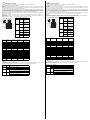
Schalter Position Betriebsart
1
Gruppe 1
und 2
OFF Not-Aus Stop 0
oder 1, lokal
wirksam
ON Wirkung als zent-
raler Not-Aus
2
Gruppe 1
und 2
OFF ohne Anlauf-/
Wiederanlauf-
sperre (Restart,
RI)
ON mit Anlauf-/Wie-
deranlaufsperre
(Restart, RI) bei
Stop Kat. 0
3
Gruppe 1
und 2
OFF ohne Relaismo-
nitor (RM)
ON mit Relaismonitor
(RM)
4
Gruppe 1
und 2
OFF Stop-Funktion
Kat. 0
ON Stop-Funktion
Kat. 1
Zeit-
wert / s
Schalter 1
Gruppe1 und 2
Schalter 2
Gruppe1 und 2
Schalter 3
Gruppe1 und 2
Schalter 4
Gruppe1 und 2
0,0 OFF OFF OFF OFF
0,3 ON OFF OFF OFF
0,4 OFF ON OFF OFF
0,5ONONOFFOFF
0,63 OFF OFF ON OFF
0,8 ON OFF ON OFF
1,0 OFF ON ON OFF
1,3ONONONOFF
1,6 OFF OFF OFF ON
2,0 ON OFF OFF ON
2,5 OFF ON OFF ON
3,2ONONOFFON
4,0 OFF OFF ON ON
5,0 ON OFF ON ON
6,3 OFF ON ON ON
8,0ONONONON
Anzeige LED Bedeutung
OSSD rot OSSD-Ausgänge abgeschaltet
grün OSSD-Ausgänge eingeschaltet
RI gelb Dauerlicht: Schutzfeld frei, OSSD Aus, Anlaufbereitschaft,
Restart-Taste betätigen
Blinkend (5 Hz): Fehler auf der Karte, in der Abschaltgruppe
oder Systemfehler
I1, I2 gelb Dauerlicht: Sensorkanal geschlossen
Blinkend (5 Hz). Fehler Sensorkanal
Lage der DIP-Schalter
Funktion
Gruppe 2
Funktion
Gruppe 1
Zeitfunktion
Gruppe 2
Zeitfunktion
Gruppe 1
ON OFF
12341234
12341234
Switch Position Operation type
1
Group 1
and 2
OFF Emergency-Stop
0 or 1, effective
locally
ON Function as cen-
tral Emergency-
Stop
2
Group 1
and 2
OFF Without restart
interlock (restart,
RI)
ON With restart inter-
lock (restart, RI)
for stop cat. 0
3
Group 1
and 2
OFF Without relay
monitor (RM)
ON With relay moni-
tor (RM)
4
Group 1
and 2
OFF Stop function
cat. 0
ON Stop function
cat. 1
Time
value /
s
Switch 1
Group 1 and 2
Switch 2
Group 1 and 2
Switch 3
Group 1 and 2
Switch 4
Group 1 and 2
0.0 OFF OFF OFF OFF
0.3 ON OFF OFF OFF
0.4 OFF ON OFF OFF
0.5ONONOFFOFF
0.63 OFF OFF ON OFF
0.8 ON OFF ON OFF
1.0 OFF ON ON OFF
1.3ONONONOFF
1.6 OFF OFF OFF ON
2.0 ON OFF OFF ON
2.5 OFF ON OFF ON
3.2ONONOFFON
4.0 OFF OFF ON ON
5.0 ON OFF ON ON
6.3 OFF ON ON ON
8.0ONONONON
Display LED Meaning
OSSD red OSSD outputs switched off
green OSSD outputs switched on
RI yellow Continuous light: protected area free, OSSD off, start readi-
ness, actuate restart push button
Flashing (5 Hz): error on the card, in the switch group or
system error
I1, I2 yellow Continuous light: sensor channel closed
Flashing (5 Hz). sensor channel error
Position of the DIP switches
Function
group 2
Function
group 1
Timer function
group 2
Timer function
group 1
ON OFF
12341234
12341234
-
 1
1
-
 2
2


Pepperl+Fuchs SB4 Module 2E Bedienungsanleitung
- Typ
- Bedienungsanleitung
in anderen Sprachen
Verwandte Papiere
-
Pepperl+Fuchs SB4 Module 2E/165 Bedienungsanleitung
-
-
-
-
-
-