Pepperl+Fuchs VAA-2E2A-KE1-SE Benutzerhandbuch
- Typ
- Benutzerhandbuch

Hinweise zur Benutzung der Anschluss- und Betriebsanleitung
Diese Anschluss- und Betriebsanleitung enthält Informationen über den bestim-
mungsgemäßen und effektiven Einsatz des Moduls.
Sicherheits- und Warnhinweise sind mit dem Symbol gekennzeichnet.
Pepperl+Fuchs GmbH haftet nicht für Schäden, die durch unsachgemäße Benut-
zung entstehen. Zur sachgerechten Verwendung gehört auch die Kenntnis dieser An-
leitung.
© Nachdruck und Vervielfältigung, auch auszugsweise, nur mit ausdrücklicher
Genehmigung durch:
Pepperl+Fuchs GmbH
Lilienthalstraße 200 * 68301 Mannheim
Telefon (06 21) 7 76-11 11 * Telefax (06 21) 7 76 27-11 11
Internet http://www.pepperl-fuchs.com
Diese Betriebsanleitung ist Bestandteil des Lieferumfangs.
Technische Daten
Sicherheitstechnische Kenndaten
Zur Ermittlung der sicherheitstechnischen Kenndaten (PFD und PFH) sind die Werte
aller in dieser Funktion benutzten Komponenten zu berücksichtigen. Das Modul VAA-
2E2A-KE1-SE liefert keinen nennenswerten Beitrag zu PFD oder PFH des Gesamt-
systems. Die Werte anderer Komponenten entnehmen Sie bitte der jeweiligen Doku-
mentation.
Ansprechzeiten
Die Ansprechzeit entspricht der Durchlaufzeit im AS-i Slave; sie ist die maximal, d.h.
auch im Fehlerfall, benötigte Zeit zwischen dem Öffnen der Schaltkontakte und der
Verfügbarkeit im AS-i Chip des Slaves. Für die Berechnung des Sicherheitsabstands
einer Schutzeinrichtung müssen Sie u.a. folgendes berücksichtigen:
• die Ansprechzeit des AS-i Slaves
• die Ansprechzeit des Sicherheitsmonitors
• die Nachlaufzeit der Maschine oder Anlage.
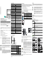
Bedienelemente und Klemmenbelegung
Montage
Die Montage des Moduls erfolgt auf 35 mm Normschienen nach EN 60715.
Setzen Sie das Modul zur Montage an der Oberkante der Normschiene an und
schnappen Sie es dann an der Unterkante ein.
Anforderungen an Spannungsversorgung +24 VEXT (AUX)
Wartung
Die einwandfreie Funktion des Module innerhalb des absichernden Systems, d. h. das
sichere Abschalten bei Auslösung eines zugeordneten sicherheitsgerichteten Sen-
sors oder Schalters, ist vom Sicherheitsbeauftragten mindestens jährlich zu kontrol-
lieren.
Adressierung
Für die Adressierung des Moduls kann sowohl ein AS-i-Master als auch ein Handheld
verwendet werden. Ein Handheld wird hierfür an die Adressierbuchse am Modul an-
geschlossen.
LED Statusanzeige
Anschlussbeispiele
Originalbetriebsanleitung VAA-2E2A-KE1-SE
AS-i Safety Eingangsmodul
für opto-elektronische Schutzeinrichtungen
Bestimmungsgemäßer Gebrauch
Das „AS-i Safety Eingangsmodul“ ist eine dezentrale Eingabe-Baugrup-
pe zur Integration von Sicherheitskomponenten in das Sicherheitsbus-
system AS-i Safety at Work (SaW).
Das Modul erzeugt eine sichere SaW-Codefolge, wenn sich das Ein-
gangssignal innerhalb eines parametrierbaren Fensters befindet.
Das Modul ist für den Einsatz von Sicherheitsanwendungen bis
Kategorie 4 / PL e / SIL 3 zugelassen.
Das Modul darf nur in den Grenzen seiner technischen Daten betrieben
werden. Es darf nur mit den vorgeschriebenen Strom- und Spannungs-
werten betrieben werden.
Zum Anschluss und zur Inbetriebnahme der SaW-Baugruppe gehört die
Kenntnis der Anschluss- und Betriebsanleitung sowie des Benutzer-
handbuchs der ASIMON-Konfigurations- und Diagnosesoftware.
Der Besteller hat die Rückverfolgbarkeit der Geräte über die Serien-
nummer sicherzustellen.
Personenschutzfunktion
Das Modul erfüllt eine Personenschutzfunktion. Unsachgemäßer Ein-
bau beeinträchtigt die Funktion! Der Hersteller der Maschine/Anlage, an
der das sicherheitsgerichtete System eingesetzt wird, ist verantwortlich
für die korrekte und sichere Gesamtfunktion aller einzelnen Sicherheits-
komponenten! Je nach Auswahl der verwendeten Sicherheitsbauteile
kann die Einstufung des gesamten Sicherheitssystems auch in eine
niedrigere Sicherheitskategorie erfolgen!
Ausgabedatum: 2015-10-26
Technische Änderungen vorbehalten
YoC: 2015
PEPPERL+FUCHS
Lilienthalstraße 200
D-68307 Mannheim
Made in Germany
VAA-2E2A-KE1-SE
AS-i Safety Slave IP20
Anschluss
Anschluss 3 x COMBICON
Länge Anschlusskabel unbegrenzt1
1. Schleifenwiderstand ≤150 Ω
AS-i
AS-i-Profil S-7.B.1, ID1=F
Adresse 1 Single Slave
Bemessungsbetriebsspannung 22 … 31,6 V
Erforderliches Master Profil ≥M3
Ab AS-i Spezifikation 2.1
Max. Stromaufnahme 35 mA
AUX
Spannung 24 V (20 … 30 VDC) (PELV)
Max. AUX Stromaufnahme 4 A max.
Eingang
Eingänge 2 / 1 sichere Eingänge mit zwei Kanälen für OSSDs
Versorgungsspannung aus AUX
Stromversorgung externer Senso-
ren 1,8 A aus AUX
Schaltschwelle Vin > 11 V für High-Level,
Eingangsstrom ≥ 2,5 mA bei 15 V
Testpuls OSSD Eingang 0 … 50 Hz
Impulslänge OSSD Eingang Uaux ≥21,5 V= 0 ... 1 ms Testpulse möglich
Uaux ≥ 17 V= 0 ... 0,8 ms Testpulse möglich
Uaux <17 V= 0 ... 0,6 ms
Ausgang
Anzahl 2, elektronisch, kurzschlussfest
Versorgungsspannung aus AUX
Max. Ausgangsstrom 1 A pro Ausgang (siehe Diag. <Derating Ausgangs-
strom>)
Anzeige
LED Anzeige siehe Tabelle “LED Statusanzeige”
Umwelt
Umgebungstemperatur 0 °C ... +55 °C
Lagertemperatur -40°C ... +85°C
Schutzart nach DIN EN 60 529 IP20
Zulässige Schock- und Schwing-
beanspruchung
≤15 g, T ≤11 ms
10 ... 55 Hz, 0,5 mm Amplitude
Maße (L / B / H in mm) 99,6 / 22,5 / 50,5
Derating Ausgangsstrom
Kenndaten Wert Norm
Sicherheitskategorie 4 EN ISO 13849-1
Performance Level (PL) e
Safety Integrity Level (SIL) 3 EN 62061
Gebrauchsdauer (TM) [Jahr] 20 EN ISO 13849-1
Maximale Einschaltdauer [Monat] 12 EN 62061
PFD 8,00E-07 EN 61508
PFHD [1/h] 1,48E-09 EN 61508
2,83E-09 EN 62061
Max. Ansprechzeit [ms] 10 EN 62061
0,5A
1A
45°C 55°C
I OUT, max. [A]
Tamb [°C]
Informationen zu den Ansprechzeiten der jeweiligen Geräte finden Sie
in der dazugehörigen Betriebsanleitung.
S1, S2 Anschluss Eingang OSSD 1/2
O1, O2 Anschluss Ausgang O1/O2
0 Vext.out Bezugspotezial für die Ausgänge und Schut-
zeinrichtungen
24 Vext.out Versorgungsspannung der elektronischen
Schutzeinrichtungen
AS-i +/– Anschluss an AS-i-Bus
AUX+/- ext.in
Versorgungsspannung für die konventionellen
Ausgänge und Spannungsversorgungseingang
für die elektrischen Schutzeinrichtungen
ADDR Adressierbuchse
Montieren Sie das Sicherheitsschaltgerät in einem Schaltschrank mit ei-
ner Schutzart von mindestens IP54!
Fachgerecht installieren
Die elektrische Installation ist von eingewiesenem Fachpersonal durch-
zuführen. Bei der Installation ist darauf zu achten, dass Versorgungs-
und Signalleitungen und auch die AS-i Busleitung getrennt von Kraft-
stromleitungen verlegt sind. Im Schaltschrank ist darauf zu achten, dass
bei Schützen eine entsprechende Funkenlöschung verwendet wird. Bei
Antriebsmotoren und -bremsen ist auf die Installationshinweise in den
entsprechenden Bedienungsanleitungen zu achten. Bitte beachten Sie,
dass die maximale Leitungslänge für die AS-i Busleitung 100 m beträgt.
Darüber hinausgehende Leitungslängen erfordern den Einsatz geeigne-
ter Leitungsverlängerungen.
Bei dem Modul handelt es sich um eine ESD gefährdete Baugruppe. Bei
der Montage sind die einschlägigen ESD-Schutzmaßnahmen einzuhal-
ten!
Die extern anschließbaren Stromkreise müssen sicher vom Netz ge-
trennt sein!
Die Spannungsversorgung der +24 VEXT darf nur über SELV- oder
PELV-Netze erfolgen.
Die AS-i bzw. die 24 V-Versorgung muss aus einem PELV-Netzteil er-
folgen!
+
ASI
–+–
AUX
(24 VDC)
[1]
[2]
0,6 Nm (5 Ibf
. in)
0,6 x 3,5 mm
7
7
AWG 24 ... 12
0,2 ... 2,5 mm2
0,2 ... 2,5 mm2
Dazu ist jeder sicherheitsgerichtete AS-i Slave mindestens einmal pro
Jahr zu betätigen und das Schaltverhalten durch Beobachtung der Aus-
gangskreise des AS-i Sicherheitsmonitors zu kontrollieren.
Abhängig vom für die Gesamtversagenswahrscheinlichkeit gewählten
PFD-Wert ist die maximale Einschaltdauer und die Gesamtbetriebsdau-
er zu beachten.
Bei Erreichen der maximalen Einschaltdauer (s. „Sicherheitstechnische
Kenndaten“) ist die ordnungsgemäße Funktion des Sicherheitssystems
durch Anforderung der Abschaltfunktion zu überprüfen.
Bei Erreichen der maximalen Gebrauchsdauer (TM) ist das Gerät vom
Hersteller auf seine ordnungsgemäße Funktion im Herstellerwerk zu
überprüfen.
LEDs Status Signal / Beschreibung
PWR
(grün)
keine Betriebspannung
Betriebspannung vorhanden
FAULT
(rot)
AS-i-Kommunikation OK
Peripheriefehler
Kommunikationsfehler
AUX
(grün)
Hilfsspannung fehlt
Hilfsspannung OK
Out 1/2
(gelb)
Ausgang ausgeschaltet
Ausgang eingeschaltet
In1/2
(gelb)
Der entsprechende Eingang ist nicht geschaltet
Der entsprechende Eingang ist geschaltet
LED an LED blinkend LED aus
FE
FE
S1
0 V
ext out
S2
24 V
ext out
0 V
ext out
24 V
ext out
transmitter
receiver
laser scanner
S1
0 V
ext out
S2
24 V
ext out
transmitter/
receiver
FE
S1
0 V
ext out
S2
24 V
ext out
Out 1 / Out 2
0 V
ext out
O2
O1
0 V
ext out
O1
Out
1
O2
0 V
ext out
Out
2


Notes on using these connection and operating instructions
These connection and operating instructions contain information regarding the proper
and effective use of the module.
Safety precautions and warnings are designated by the symbol.
Pepperl+Fuchs GmbH is not liable for damage resulting from improper use of its
equipment. Familiarity with these instructions constitutes part of the knowledge re-
quired for proper use.
© Reprint and reproduction, in whole or in part, only with the explicit permission of:
Pepperl+Fuchs GmbH
Lilienthalstraße 200 * 68301 Mannheim
Telefon (06 21) 7 76-11 11 * Telefax (06 21) 7 76 27-11 11
Internet http://www.pepperl-fuchs.com
This operating instruction is a part of the scope of delivery.
Technical data
Safety characteristics
To determine the safety characteristics (PFD and PFH), the values of all components
used in this function are to be considered. The module VAA-2E2A-KE1-SEprovides
no significant contribution to the PFD or PFH values of the complete system. For the
values of other components, please refer to the relevant documentation.
Response time
The response time corresponds to the processing time in the AS-i slave. It is the max-
imum (i.e. also in the case of a fault) required time between the opening of the switch-
ing contacts and the operational availability in the AS-i chip of the slave. For the
computation of the safety distance of a protective device, the following things (among
others) must be considered:
• the response time of the AS-i slave
• the response time of the safety monitor
• the follow-up time of the machine or production line.
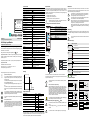
Operating elements and terminal connections
Assembly
The module is mounted on 35 mm standard rails in accordance with EN 60715.
For assembling, position the module on the upper edge of the standard rail and then
snap it onto the bottom edge.
Requirements on the power supply +24 VEXT (AUX)
Maintenance
The proper function of the module within the system to be secured, i.e. the safe shut-
down following the triggering of an assigned safety related sensor or switch, is to be
checked at least once a year by the safety officer.
Addressing
For the addressing of the module, both an AS-i master and a hand-held can be used.
If a hand-held is being used, it should be connected to the addressing socket on the
module.
LED status display
Connection examples
Translation
of the original operating instructions VAA-2E2A-KE1-SE
AS-i Safety Input Module
for optoelectronic protective devices
Specified normal operation
The „AS-i Safety Input Module“ is a decentralized input module for the
integration of safety components into the AS-i Safety at Work (SaW)
safety bus system.
The module provides a safety SaW code sequence if the input signal is
within the adjustable safety range.
The module is approved for safety applications up to Category 4 / PL e /
SIL 3.
The module may only be operated within the limits of its technical spec-
ifications. It may only be operated with the specified current and voltage
values.
For connecting and commissioning the module, comprehension of the
operating instructions as well as the operating instructions of ASIMON
configuration and diagnostic software is necessary.
The orderer has to guarantee the traceability of the devices via the serial
number.
Person protection function
The module fulfills a person protection function. Improper installation im-
pairs the function! The manufacturer of the machine/plant in which the
safety related system is used is responsible for the correct and safe total
function of every individual safety component! Depending on the choice
of safety devices used, the safety system as a whole may also be as-
signed to a lower safety category!
Issue date: 2015-10-26
Subject to change without prior notice
YoC: 2015
PEPPERL+FUCHS
Lilienthalstraße 200
D-68307 Mannheim
Made in Germany
VAA-2E2A-KE1-SE
AS-i Safety Slave IP20
Connection
Connection 3 x COMBICON
Length of connector cable unlimited1
1. loop resistance ≤ 150 Ω
AS-i
Profile S-7.B.1, ID1=F
Address 1 Single Slave
Operating voltage 22 … 31,6 V
Required Master profile ≥M3
Since AS-i specification 2.1
Max. current input 35 mA
AUX
Voltage 24 V (20 … 30 VDC) (PELV)
Max. current input 4 A max.
Input
Number 2 / 1 safety inputs with two channels for OSSDs
Power supply aus AUX
Power supply
for external sensor 1,8 A aus AUX
Switching threshold Vin > 11 V for High-Level,
Input current ≥ 2,5 mA at 15 V
OSSD input test pulses 0 … 50 Hz
OSSD input test pulse width Uaux ≥21,5 V= 0 ... 1 ms test pulses possible
Uaux ≥ 17 V= 0 ... 0,8 ms test pulses possible
Uaux <17 V= 0 ... 0,6 ms
Output
Number 2, electronic, short circuit protected
Power supply out of AUX
Max. output current 1 A per output (see diag. <Derating>)
Display
LED display see table “LED status display”
Environment
Ambient temperature 0 °C ... +55 °C
Storage temperature -40°C ... +85°C
Protection category (EN 60529) IP20
Allowable shock and vibration
stress
≤15 g, T ≤11 ms
10 ... 55 Hz, 0,5 mm Amplitude
Dimensions (L / B / H in mm) 99,6 / 22,5 / 50,5
Derating
Characteristics Value Standard
Safety category 4 EN ISO 13849-1
Performance level (PL) e
Safety Integrity Level (SIL) 3 EN 62061
Service life (TM) [year] 20 EN ISO 13849-1
Maximal power-on time [month] 12 EN 62061
PFD 8,00E-07 EN 61508
PFHD [1/h] 1,48E-09 EN 61508
2,83E-09 EN 62061
Max. system response time [ms] 10 EN 62061
0,5A
1A
45°C 55°C
I OUT, max. [A]
Tamb [°C
Information about the response times of the respective devices can be
found in the corresponding operating instructions.
In1, In2 Connection to input OSSD 1/2
O1, O2 Connection to output O1/O2
0 Vext.out Reference potential for the outputs and protec-
tive devices
24 Vext.out Supply voltage for the optoelectronic protective
devices
AS-i +/– AS-i connection
AUX+/- ext.in
Supply voltage for the conventional outputs and
voltage supply input for the electrical protective
devices
ADDR Addressing socket
Install the safety relay in a control cabinet with a minimum protection
type of IP54!
Have installation done professionally
Electrical installation is to be performed by a trained expert. During in-
stallation, care must be taken that supply and signal cables and also the
AS-i bus cable are laid separately from high-voltage cables. In the
switch cabinet, it must be ensured that appropriate spark quenching
equipment is used with contactors. Where drive motors and brakes are
used, attention must be paid to the installation instructions in the corre-
sponding operating instructions. Please note that the maximum cable
length of the AS-i bus cable is 100 m. Cables above that length require
the use of a suitable circuit extension.
The module is an ESD unsecured building group. When assembling the
relevant ESD preventive measures are to be kept!
The externally connectable circuits must be reliably separated from the
mains!
The power supply of the +24 VEXT may only occur via SELV or PELV
networks.
The AS-i and/or the 24 V must be supplied by a PELV power supply!
+
ASI
–+–
AUX
(24 VDC)
[1]
[2]
0,6 Nm (5 Ibf
. in)
0,6 x 3,5 mm
7
7
AWG 24 ... 12
0,2 ... 2,5 mm2
0,2 ... 2,5 mm2
For this purpose, every safety related AS-i slave must be activated at
least once per year and the switching behavior must be inspected by
monitoring the output circuits of the AS-i safety monitor.
The maximum power-on time and total operating time depends on the
PFD value selected for the overall failure probability.
When the maximum power-on time has been reached (see safety char-
acteristics), the safety system must be checked to ensure that it is func-
tioning correctly by prompting the shutdown function.
When the maximum service life (TM) has been reached, the device must
be checked at the manufacturer's factory to ensure that it is functioning
correctly.
The proper safety function of the device must be verified in the asset in
any case!
LEDs Status Description
PWR
(green)
no supply power
supply power present
FAULT
(red)
AS-i communication ok
peripheral fault
AS-i communication error
AUX
(green)
no auxiliary voltage
auxiliary voltage ok
Out 1/2
(yellow)
output switched off
output switched on
In1/2
(yellow)
corresponding input not switched
corresponding input switched
LED on LED flashing LED off
FE
FE
S1
0 V
ext out
S2
24 V
ext out
0 V
ext out
24 V
ext out
transmitter
receiver
laser scanner
S1
0 V
ext out
S2
24 V
ext out
transmitter/
receiver
FE
S1
0 V
ext out
S2
24 V
ext out
Out 1 / Out 2
0 V
ext out
O2
O1
0 V
ext out
O1
Out
1
O2
0 V
ext out
Out
2

-
 1
1
-
 2
2
-
 3
3
-
 4
4


Pepperl+Fuchs VAA-2E2A-KE1-SE Benutzerhandbuch
- Typ
- Benutzerhandbuch
in anderen Sprachen
Verwandte Artikel
-
Pepperl+Fuchs VAS/M-2A8L-KE4-8SE-C1 Benutzerhandbuch
-
Pepperl+Fuchs VAS/M-2A8L-KE4-6SE-EV Benutzerhandbuch
-
-
-
-
-
-
-
-
Andere Dokumente
-
IFM AC041S Bedienungsanleitung
-
 Kromschroder VAA Datenblatt
-
Schneider Electric TM3SAK6R Bedienungsanleitung
-
PILZ P1HZ X1 Operating Instructions Manual
-
WAGO 4FDI / 4FRO 48 VAC / 60 VDC / 6 A PROFIsafe V2 iPar Benutzerhandbuch
-
Eaton EMS-SWD Series Benutzerhandbuch
-
WAGO 4FDI 24VDC PROFIsafe V2 iPar Benutzerhandbuch
-
-
-
