Pepperl+Fuchs SB4 Module 4CP Bedienungsanleitung
- Typ
- Bedienungsanleitung

alle Maße in mm
Electrical connection
Elektrischer Anschluss
Technische Daten
Technical data
Abmessungen
Dimensions
Adressen/Addresses
Sicherheitshinweise:
•Vor der Inbetriebnahme Betriebsanleitung lesen
• Anschluss, Montage und Einstellung nur durch Fachpersonal
Security Instructions:
• Read the operating instructions before attempting commissioning
• Installation, connection and adjustments should only be undertaken by specialist personnel
all dimensions in mm
www.pepperl-fuchs.com
Pepperl+Fuchs Group
68301 Mannheim · Germany
Tel. +49 621 776-4411
Fax +49 621 776-27-4411
E-mail: fa-inf[email protected]
Worldwide Headquarters
Pepperl+Fuchs Group · Mannheim · Germany
E-mail: fa-inf[email protected]
USA Headquarters
Pepperl+Fuchs Inc. · Twinsburg · USA
E-mail: fa-inf[email protected]
Asia Pacific Headquarters
Pepperl+Fuchs Pte Ltd · Singapore
E-mail: fa-inf[email protected]
Company Registration No. 199003130E
Klemme Funktion Kanalzuordnung
1 Empfänger 2 Eingang Eingang
2 Empfänger 2 +U Kanal 2
3 Sender 2 +U
4 Sender 2 Ausgang Ausgang
5 Empfänger 1 Eingang Eingang
6 Empfänger 1 +U Kanal 1
7 Sender 1 +U
8 Sender 1 Ausgang Ausgang
9 Sender 3 Ausgang Ausgang
10 Sender 3 +U Kanal 3
11 Empfänger 3 +U
12 Empfänger 3 Eingang Eingang
13 Sender 4 Ausgang Ausgang
14 Sender 4 +U Kanal 4
15 Empfänger 4 +U
16 Empfänger 4 Eingang Eingang
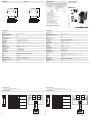
Anschlussbeispiel
(LSS = Lichtschrankensender;
LSE = Lichtschrankenempfänger)
BK
BU
LSS
BN
BU
3
4
LSS
3
1
LSE
R4
R3
R2
R1
13 14 15 16
1 2 3 4
5 6 7 8
9 10 11 12
LSE
R4
R3
R2
R1
13 14 15 16
9 10 11 12
1 2 3 4
5 6 7 8
Sicherheitsschaltgerät Modul
Safety control unit module
SB4 Module 4CP
Allgemeine Daten
Betriebsart Gleichzeitigkeit, Antivalenz
Kenndaten funktionale Sicherheit
Sicherheits-Integritätslevel (SIL) SIL 3
Performance Level (PL) PL e
Kategorie Kat. 4
Gebrauchsdauer (TM) 20 a
Typ 4
Anzeigen/Bedienelemente
Funktionsanzeige LED gelb (4x): Leuchtmelder Kanal 1 ... 4
Vorausfallanzeige LED gelb blinkend: Leuchtmelder Kanal 1 ... 4
Bedienelemente DIP-Schalter
Elektrische Daten
Betriebsspannung UB24 V DC ± 20 % , erfolgt über SB4 Housing
Eingang
Betätigungsstrom ca. 7 mA
Konformität
Funktionale Sicherheit ISO 13849-1 ; EN 61508 part1-4
Produktnorm EN 61496-1
Umgebungsbedingungen
Umgebungstemperatur 0 ... 50 °C (32 ... 122 °F)
Lagertemperatur -20 ... 70 °C (-4 ... 158 °F)
Schockfestigkeit siehe Betriebsanleitung
Vibrationsfestigkeit siehe Betriebsanleitung
Mechanische Daten
Schutzart IP20
Anschluss Schraubklemmen , Leitungsquerschnitt 0,2 ... 2 mm2
Option /165: Federzugklemmen , Leitungsquerschnitt 0,2 ... 1,5 mm2
Material
Gehäuse Polyamid (PA)
Masse ca. 150 g
Allgemeine Informationen
Bestellinformationen ohne Option /165 -> mit Schraubklemmen
mit Option /165 -> mit Federzugklemmen
Zulassungen und Zertifikate
CE-Konformität CE
UL-Zulassung cULus
TÜV-Zulassung TÜV
Terminal
Function Channel assignment
1 Receiver 2 input Input
2 Receiver 2 +U Channel 2
3 Transmitter 2 +U
4 Transmitter 2 output Output
5 Receiver 1 input Input
6 Receiver 1 +U Channel 1
7 Transmitter 1 +U
8 Transmitter 1 output Output
9 Transmitter 3 output Output
10 Transmitter 3 +U Channel 3
11 Receiver 3 +U
12 Receiver 3 input Input
13 Transmitter 4 output Output
14 Transmitter 4 +U Channel 4
15 Receiver 4 +U
16 Receiver 4 input Input
Connection example
(LSS = transmitter of light barrier;
LSE = receiver of light barrier)
BK
BU
LSS
BN
BU
3
4
LSS
3
1
LSE
R4
R3
R2
R1
13 14 15 16
1 2 3 4
5 6 7 8
9 10 11 12
LSE
R4
R3
R2
R1
13 14 15 16
9 10 11 12
1 2 3 4
5 6 7 8
05/31/2023
Date:
100,522,6
80,3
99
13 14 15 16
9 10 11 12
1 2 3 4
5 6 7 8
General specifications
Operating mode simultaneousness, antivalence
Functional safety related parameters
Safety Integrity Level (SIL) SIL 3
Performance level (PL) PL e
Category Cat. 4
Mission Time (TM) 20 a
Type 4
Indicators/operating means
Function indicator LED yellow (4x): indicator lamp channel 1 ... 4
Pre-fault indicator LED yellow flashing: Indicator lamp channel 1 ... 4
Control elements DIP-switch
Electrical specifications
Operating voltage UB24 V DC ± 20 % , via SB4 Housing
Input
Activation current approx. 7 mA
Conformity
Functional safety ISO 13849-1 ; EN 61508 part1-4
Product standard EN 61496-1
Ambient conditions
Ambient temperature 0 ... 50 °C (32 ... 122 °F)
Storage temperature -20 ... 70 °C (-4 ... 158 °F)
Shock resistance see instruction manuals
Vibration resistance see instruction manuals
Mechanical specifications
Degree of protection IP20
Connection screw terminals , lead cross section 0.2 ... 2 mm2
Option /165: Cage tension spring terminals , Cable cross-section 0.2 ... 1.5 mm2
Material
Housing Polyamide (PA)
Mass approx. 150 g
General information
Ordering information without Option /165 -> with screw terminals
with Option /165 -> spring clamp terminals
Approvals and certificates
CE conformity CE
UL approval cULus
TÜV approval TÜV
100.522.6
80.3
99
13 14 15 16
9 10 11 12
1 2 3 4
5 6 7 8
DIN A3 -> A7
Part. 182560 45-1405K
Doc.
Safety
tested
Production
monitored
Functional
Safety

Funktionsbeschreibung
Der Betrieb dieses Moduls ist nur innerhalb eines Auswertegerätes vom Typ SafeBox SB4 möglich.
Die Betriebsanleitung der SafeBox ist zu beachten.
Funktion
Das 4-kanalige Sensorkarten-Modul SB4-4CP ermöglicht den Anschluss von Lichtschranken oder -gittern bzw. kontaktbehaf-
teten Sicherheitssensoren in ein- oder zweikanaliger Ausführung. Außerdem enthält es die Mikrokontroller-Steuerung der Sa-
febox. Dieses Modul ist nur einmal in einer Safebox SB4 enthalten und muss auf den Platz2 gesteckt werden.
Auf dem Modul befindet sich eine Steckbrücke. Enthält das System weitere Baugruppen, so muß diese Steckbrücke auf den
letzten Steckplatz umgesteckt werden.
Beim Einschalten des Systems ermittelt die Software, ob an einem Kanal eine Lichtschranke oder ein kontaktbehafteter Sicher-
heitssensor angeschaltet ist und überwacht während des Betriebes seine Anwesenheit.
Kontaktbehaftete Sicherheitssensoren, die an die Safebox angeschlossen werden, müssen nach dem Öffnerprinzip arbeiten.
Ein offener Kontakt bedeutet "sicherer Zustand".
Die Kanäle 1und 2 sowie 3 und 4 können auf Gleichzeitigkeit bzw. Antivalenz überwacht werden. Bei aktivierter Gleichzeitig-
keitsüberwachung werden 2-kanalige Sicherheitseinrichtungen auf gleichzeitiges Öffnen bzw. Wechseln der Signale über-
wacht. Die Überwachungszeit beträgt 2 s.
Antivalenzüberwachung erwartet an Kanal 1 oder 3 den Öffnerkontakt und an Kanal 2 oder 4 den Schliesserkontakt. Wird die
Antivalenzüberwachung ohne Gleichzeitigkeitsüberwachung betrieben, so führt eine fehlerhafte Kontaktstellung nach ca. 60 s
zum Abschalten und der Fehlermeldung 7.
Betriebsarten
Auf der Baugruppe befinden sich 4 DIP-Schalter zur Auswahl der Funktionen Gleichzeitigkeit benachbarter Kanäle (1 und 2, 3
und 4) und antivalente Bewertung benachbarter Kanäle (1 und 2, 3 und 4). Zur Funktionswahl sind immer 2 Schalter zu betäti-
gen. Die Funktionen sind nicht bei angeschlossenen Lichtschranken wirksam.
Anzeigen
Je Kanal gibt es auf der Frontplatte des Moduls eine gelbe LED.
Function description
The operation of this module is possible only within a control unit of the type SafeBox SB4.
Is the operating instruction of the SafeBox pay attention.
Function
The 4-channel sensor card module SB4-4CP makes it possible to connect light barriers or light grids or contact safety sensors
in a one or two-channel version. In addition it contains the Micro-Controller controls of the SafeBox.
This version only exists once in a system and is always located in slot 2 of the SafeBox. The module is supplied with plug-in
jumper. If additional modules are used, this plug-in jumper must be moved.
There is a plug-in jumper on the module. If the system contains further units, this plug-in jumper onto the last slot must be moved.
When the system is switched on, the software determines whether a light barrier or a contact safety sensor is switched on at a
channel and monitors its presence during operation. Safety sensors with switching contacts, which are connected to the Safe-
Box, must operate in the switching mode "normally closed". An open contact means "safe status".
The channels 1 and 2 as well as 3 and 4 (and 5 and 6) can be monitored for simultaneousness or antivalence. If simultaneous-
ness monitoring is activated, 2 channel safety equipment is monitored for simultaneous opening or changing of the signals. The
monitoring time is 2 s.
Antivalence monitoring expects the normally closed contact at channel 1 or 3 (or 5) and the normally open contact at channel
2 or 4 (or 6). If antivalence monitoring is performed without simultaneousness monitoring, an incorrect contact position causes
a switch-off and the error message 7 after approx. 60 s .
Operation types
The assembly contains 4 DIP switches for selecting the simultaneousness functions of neighbouring channels (1 and 2, 3 and
4) and for an antivalent evaluation of neighbouring channels (1 and 2, 3 and 4 or also 5 and 6). For selecting functions, 2 selector
switches must always be actuated. The functions are not effective if light barriers are connected.
Display
For each channel, there is a yellow LED on the front panel of the module.
Schalter Position Betriebsart
1 und 3 OFF keine antivalente
Bewertung
ON antivalente
Bewertung aktiv
2 und 4 OFF keine Gleichzei-
tigkeitsbewertung
ON Gleichzeitigkeit-
bewertung aktiv
Anzeige LED Bedeutung
R1 - R4 gelb Status Lichtschranke 1 ... 4
Aus: unterbrochen
Ein: Lichtstrahl frei
Blinkend: Lichtstrahl frei, Funktionsreserve unterschrit-
ten
(Frequenz ca. 2,5 Hz)
Schnell blinkend: Fehler
(Frequenz ca. 5 Hz)
Switch Position Operation type
1 and 3 OFF No antivalent eva-
luation
ON Antivalent evalua-
tion active
2 and 4 OFF No simultaneous-
ness evaluation
ON Simultaneous-
ness evaluation
active
Display LED Meaning
R1 - R4 yellow Status of light barrier 1 ... 4
Off: light beam interrupted
On: light beam released
Flashing (2.5 Hz): light beam released, function reserve
fallen short of
Flashing (5 Hz): error
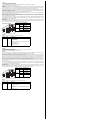
Lage der DIP-Schalter
ON
OFF
4 3 2 1
Position of the DIP switches
ON
OFF
4 3 2 1
-
 1
1
-
 2
2


Pepperl+Fuchs SB4 Module 4CP Bedienungsanleitung
- Typ
- Bedienungsanleitung
in anderen Sprachen
Verwandte Artikel
-
Pepperl+Fuchs SB4 Module 4CP/165 Bedienungsanleitung
-
-
-
-
-
-
-
-
-