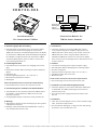
SICK CDB730-001 Connection Modula for TiM3xx Laser Scanner Bedienungsanleitung
- Typ
- Bedienungsanleitung

1 # 88014595/YTX0/2016-03 © SICK AG · Germany · All rights reserved · Subject to change without notice · Irrtümer und Änderungen vorbehalten
CDB730-001
1. Bestimmungsgemäße Verwendung
■Anschlussmodul zum Anschluss eines Laserscanners TiM3xx
an die Peripherie und Stromversorgung. Der Laserscanner
TiM31x/32x wird direkt an das Modul angeschlossen. Bei Bedarf
der Laserscanner TiM35x/36x mithilfe der Adapterleitung Artikel-
Nr. 2063181. Im Folgenden werden alle Laserscanner TiM3xx
vereinfacht TiM3xx genannt, außer an Stellen, an denen eine
Unterscheidung erforderlich ist.
2. Produkteigenschaften
■Anschlussklemmen für Schaltein- und -ausgänge, Stromversor-
gung
■Durch Deckel sichtbar: LEDs zur Anzeige von aktiven Schaltaus-
gängen
■Schutzart IP 65
■Betriebsumgebungstemperatur –35 °C bis +40 °C
■Montierbar bei geschlossenem Deckel
■Wartungsfrei
Weitere Produktinformationen und EU-Konformitätserklärung
Siehe Produktseite im Internet unter www.sick.com/cdb.
3. Voraussetzungen zur Installation und Inbetriebnahme
■Anschlusspläne in der Technischen Information TiM3xx (Artikel-
Nr. 8014317), siehe Produktseite TiM3xx im Internet unter
www.sick.com/tim3xx
■Versorgungsspannung DC 9 V bis 28 V, erzeugt nach IEC 742
4. Montage
■Abgenommener Deckel mit Klemmenbelegung um 180° gedreht
in Parkposition arretierbar.
■Bohrungs- und Gehäusemaße siehe Maßbild (Abb. 1, Seite 2),
max. Schraubendurchmesser 4 mm.
Anschlussmodul
für Laserscanner TiM3xx
Betriebsanleitung
Operating Instructions
Connection Module for
TiM3xx Laser Scanner
1. Intended use
■Connection module for connecting a TiM3x laser scanner
to the peripheral equipment and power supply. Connect the
TiM31x/32x laser scanner directly to the module. Connect the
TiM35x/36x laser scanner using the adapter cable Part no.
2063181. All TiM3x laser scanners are referred to as TiM3xx
below, except in such text passages where a differentiation of the
models is required.
2. Features
■Terminals for switching inputs/outputs and power supply
■Externally visible LEDs for displaying active switching outputs
■Enclosure rating IP 65
■Operation ambient temperature range –35 °C to +40 °C
■Installation possible with closed cover
■Maintenance-free
Further Product Information and EU Conformity Declaration
See product page on the Internet www.sick.com/cdb.
3. Installation and Commissioning Requirements
■Connection diagrams in the Technical Information TiM3xx (Part
no. 8014318), see TiM3xx product page on the Internet at
www.sick.com/tim3xx
■9 V to 28 V DC power supply generated in accordance with
IEC 742
4. Installation
■Cover with connection diagram can be removed, rotated through
180°, and locked in park position.
■See dimensioned drawing (Fig. 1, Page 2) for hole and housing
dimensions, max. screw diameter 4 mm.
SPS/PLC
9 V ... 28 V DC
Ansteuerung der
Schalteingänge
Trigger for
switching inputs
TiM3xx
"OUT 4"
"OUT 1"
"OUT 2"
"OUT 3"
"IN 4"
"IN 1"
"IN 2"
"IN 3"
CDB730-001

2 # 8 8014595/YTX0/2016-03© SICK AG · Germany · All rights reserved · Subject to change without notice · Irrtümer und Änderungen vorbehalten
OUT 1
OUT 2
OUT 3
OUT 4
Power
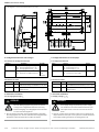
Maßbild/dimensioned drawing
Alle Angaben in mm (inch)/All dimensions in mm (inch)
5. Kongurationselemente und Anzeigen
5.1 Funktion der Kongurationsschalter
5. Conguration Elements and Displays
5.1 Conguration Switches
Abb. 1: Abmessungen des CDB730-001/Fig. 1: Dimensions of the CDB730-001
5.2 Funktion der LEDs
LED Farbe Funktion
Power (U
IN
*) Grün Leuchtet, wenn die Versorgungsspannung am
CDB730-001 anliegt und Schalter S 1 auf „ON“
OUT 1, 2, 3, 4 Orange Leuchtet, wenn der entsprechende Ausgang des
TiM3xx schaltet
5.2 Function of LEDs
LED Color Function
Power (U
IN
*) Green Lights up when the power supply is connected
(U
IN
*) to the CDB730-001 and switch S 1 is set to "ON"
OUT 1, 2, 3, 4 Orange Lights up when the corresponding output of the
TiM3xx switches
Schalter Funktion Default
S 1 (Power) Anliegende Versorgungsspannung: ON
ON: Versorgungsspannung U
IN
* ein
OFF: Versorgungsspannung U
IN
* aus
S 3 (SGND-GND) Bezugspotenzial für Sensor-GND: ON
ON: Verbunden mit GND des Sensors (nicht
änderbar)
Switch Function Default
S 1 (Power) Power supply: ON
ON: Supply voltage U
IN
* on
OFF: Supply voltage U
IN
* off
S 3 (SGND-GND) Reference potential for sensor GND: ON (xed)
ON: Connected to sensor GND
6. Electrical Installation
6.1 Supply voltage U
IN
(V
IN
)
Risk of injuries due to electrical current!
If the supply voltage is provided by a power supply
unit, insufcient electrical insulation between input
and output circuit of the unit can cause an electric
shock.
Only use a power supply unit which output circuit is safely electri-
cally isolated from the input circuit by means of double insulation
and a safety isolating transformer according to IEC 742.
6. Elektrische Installation
6.1 Versorgungsspannung U
IN
Verletzungsgefahr durch elektrischen Strom!
Wird die Versorgungsspannung durch ein Netzteil
erzeugt, kann mangelhafte elektrische Trennung
zwischen Eingangs- und Ausgangskreis des Netzteils
zu einem Stromschlag führen.
GEFAHR
Nur ein Netzteil verwenden, dessen Ausgangskreis gegenüber
dem Eingangskreis eine sichere elektrische Trennung durch Dop-
pelisolation und Sicherheitstrafo nach IEC 742 besitzt.
DANGER

3 # 88014595/YTX0/2016-03 © SICK AG · Germany · All rights reserved · Subject to change without notice · Irrtümer und Änderungen vorbehalten
6.2 Verdrahtung des CDB730-001
■Elektroinstallation nur durch ausgebildetes Fachpersonal durch-
führen.
■Bei Arbeiten in elektrischen Anlagen die gängigen Sicherheits-
vorschriften beachten.
■Elektrische Verbindungen nur im spannungsfreien Zustand her-
stellen oder lösen.
■Zur Beschaltung der Schalteingänge/-ausgänge des TiM3xx die
Anschlusspläne in der Technischen Information TiM3xx (Artikel-
Nr. 8014317) verwenden.
■Klemmenbelegung siehe Anschlussbild unten oder im Deckel.
■Um Störeinüsse zu vermeiden, Leitungen möglichst nicht paral-
lel zu Stromversorgungs- und Motorleitungen verlegen.
1. Leitung des TiM31x/32x an die 15-pol. D-Sub-HD-Dose des
CDB730-001 anschließen. Für den TiM35x/36x mit 12-pol. M12-
Stecker die Adapterleitung Artikel-Nr. 2063181 verwenden.
2. Alle anderen Leitungen über Leitungsverschraubungen an den
Anschlussklemmen des CDB730-001 auegen.
3. Anwenderseitige Schirmung am CDB730-001 auegen (An-
schlussklemme „Shield“).
6.2 Wiring the CDB730-001
■Electrical installation should only be carried out by qualied staff.
■Observe the current safety regulations when working on electrical
systems.
■Connect or disconnect current linkages only under de-energized
conditions.
■For wiring the switching inputs/outputs of the TiM3xx use the
connecting diagrams in the Technical Information TiM3xx (Part
no. 8014318).
■For terminal assignment, see connection diagram below or inside
the cover.
■To prevent interference, do not lay cables parallel to power supply
or motor cables.
1. Connect the TiM31x/32x cable to the 15-pin D-Sub HD female
connector of the CDB730-001. For TiM35x/36x with 12-pin M12
male connector use the adapter cable part. no. 2063181.
2. Connect all other cables to the terminals of the CDB730-001
provided using cable glands.
3. Connect the shield of your system to the CDB730-001 ("Shield"
terminal).
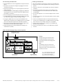
Aufbau, Klemmenbelegung/design, terminal assignment
LEDs
Abb. 2: Belegung der Klemmen und Schalter/Fig. 2: Functional attribution of terminals and switches
(Kongurationsschalter)
(Conguration switch)
Anschluss TiM3xx
TiM3xx connection
U
IN
* = Versorgungspannung U
IN
nach
Schalter S1 und interner Sicherung.
U
IN
* = Power supply voltage U
IN
behind switch S1 and internal fuse.
Klemmenleisten
Terminal strips
Hinweis:
Die Beschriftung der Leiterkarte kann
produktionsbedingt in Details von der
Darstellung der Klemmenbelegung links
abweichen.
Note:
The labelling of the circuit board can
differ in some details from the terminal
assignment shown on the left side due to
production work ow.

4 # 8 8014595/YTX0/2016-03© SICK AG · Germany · All rights reserved · Subject to change without notice · Irrtümer und Änderungen vorbehalten
7. Sicherheit: Gefahr durch Ausgleichsströme bei unter-
schiedlichen Erdpotenzialen
7.1 Änderung der Norm 60950-1
Die Norm 60950-1 (2006-04) wurde mit der Änderung A11 (2009-
03) erweitert. Die Änderung ist ab 01-12-2010 verbindlich.
Das CDB730-001 ist auf elektrische Sicherheit gemäß dieser geän-
derten Norm ausgelegt und geprüft.
7.2 Voraussetzungen für den sicheren Betrieb des CDB730-001
und des daran angeschlossenen TiM3xx
Der TiM3xx wird über ein CDB730-001 mit geschirmten Leitungen
an die Peripherie geräte (Ansteuerung der Schalteingänge, Aktoren
für die Schaltausgänge, Stromversorgung etc.) angeschlossen. Der
Lei tungsschirm z.B. der Anschlussleitung liegt dabei am Metallge-
häuse des TiM3xx sowie an der Klemmleiste des CDB730-001 auf.
Über das CDB730-001 bietet sich die Erdung des TiM3xx an.
Falls die Peripheriegeräte ebenfalls Metallgehäuse besitzen und der
Leitungs schirm ebenfalls an deren Gehäuse auiegt, wird davon
ausgegangen, dass alle beteiligten Geräte in der Installation das
gleiche Erdpotenzial haben. Dies erfolgt z.B. durch die Montage
der Geräte auf lei tende Metallächen, die fachgerechte Erdung der
Geräte/Metallächen in der Anlage und falls erforderlich, einen nie-
derimpedanten und stromtragfähigen Poten zialausgleich zwischen
Bereichen mit unterschiedlichen Erdpotenzialen.
Sind diese Bedingungen nicht erfüllt, z.B. bei Geräten innerhalb
eines weit verteilten Sys tems über mehrere Gebäude, können
Potenzialausgleichströme über die Leitungsschirme zwischen den
Geräten aufgrund unterschiedlicher Erdpotenziale ießen.
7. Safety: Risk of equalizing currents at different ground
potentials
7.1 Change to standard 60950-1
Standard 60950-1 (2006-04) has been added to with the change
A11 (2009-03). As of December 1, 2010, the change is obligatory.
The CDB730-001 has been designed and checked according to the
changed standard.
7.2 Conditions for the safe operation of the CDB730-001 and the
connected TiM3xx
The TiM3xx is connected to the peripheral devices (trigger for
switching inputs, actuators for switching outputs, power supply) via
a CDB730-001 using shielded cables. The cable shield on the con-
necting cable for instance, lies on the metal housing of the TiM3xx
and on the terminal strip of the CDB730-001. The grounding of the
TiM3xx can be performed via the CDB730-001.
If the peripheral devices also have metal housing and if the cable
shield also lies on their housing, it is assumed that all devices
involved in installation have the same ground potential. This is
achieved for instance by mounting the devices on conductive metal
surfaces, correctly grounding the devices/metal surfaces in the
system and if necessary via a low-impedance and stable current
carrying equipotential bonding between areas with different ground
potentials.
If these conditions are not met, e.g. on devices in a widely distrib-
uted system over several buildings, potential equalization currents
may, due to different ground potentials, ow along the cable shields
between the devices.
Verletzungs-/Beschädigungsgefahr durch elektrischen Strom!
Potenzialausgleichsströme zwischen dem TiM3xx und/oder den
Peripheriegeräten können ggf. folgende Auswirkungen haben:
■Gefährliche Spannungen am Metallgehäuse z.B. des TiM3xx
■Fehlverhalten oder die Zerstörung der Geräte
■Schädigung/Zerstörung des Leitungsschirms durch Erhitzung
sowie Leitungsbrände
Wo die örtlichen Gegebenheiten ein sicheres Erdungskonzept
(gleiches Potenzial in allen Erdungspunkten) nicht erfüllen, Maß-
nahmen gemäß dem nachfol genden Kapitel ergreifen.
GEFAHR
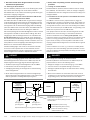
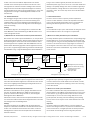
Abb. 3: Ströme in den Leitungsschirmen durch Erdpotenzialunterschiede/Fig. 3: Currents in the cable shields due to differences in ground potential
DANGER
Risk of injury/risk of damage via electrical current!
Potential equalization currents between the TiM3xx and/or the
peripheral devices can have the following effects:
■Dangerous voltages on the metal housing e.g. of the TiM3xx
■Incorrect function or irreparable damage to the devices
■Damage/irreparable damage of the cable shield due to heating
and cable res
Where local conditions are unfavorable and thus do not meet
conditions for a safe earthing method (same ground potential at
all grounding points), take measures from the next chapter.
TiM3xx
geschlossene Stromschleife mit Ausgleichs-
strömen über Leitungsschirm.
closed current loop with equalizing currents
via cable shield
Erdungspunkt 2
grounding point 2
Erdungspunkt 1
grounding point 1
Erdpotenzialdifferenz/grounding potential difference
Ansteuerung für
Schalteingänge
Trigger for
switching inputs
Aktoren für
Schaltausgänge
Actuators for
switching outputs
Strom-
versorgung
Power supply
unit
I
U
CDB730-001
= Metallgehäuse/metal housing
= Kunststoffgehäuse/plastic housing
= geschirmte elektrische Leitung/
shielded electrical cable

5 # 88014595/YTX0/2016-03 © SICK AG · Germany · All rights reserved · Subject to change without notice · Irrtümer und Änderungen vorbehalten
Erdungspunkt 1/grounding point 1
Elektro-
optischer
Trenner
Electro-optical
converter
Elektro-
optischer
Trenner
Electro-optical
converter
Erdungspunkt 2/grounding point 2
TiM3xx
Ansteuerung für Schalteingänge
Trigger for switching inputs
Aktoren für Schaltausgänge
Actuators for
switching outputs
= Metallgehäuse/metal housing
= geschirmte elektrische Leitung/
shielded electrical cable
= Lichtwellenleiter/
fiber optic cable
Zu Abb. 3. Durch unterschiedliche Erdpotenziale von Geräten
innerhalb eines verteilten Systems kö nnen hohe Ströme in den
Leitungsschirmen auftreten und diese schädigen oder zerstören.
Aufgrund des unzureichenden Erdpotenzialausgleichs entstehen
Spannungsdifferenzen zwischen den Erdungspunkten 1 und 2. Über
die geschirmten Leitungen und Metallgehäuse schließt sich die
Stromschleife.
7.2 Abhilfemaßnahmen
Die vorrangige Lösung für das Vermeiden von Potenzialausgleichs-
strömen auf den Lei tungsschirmen ist die Sicherstellung eines
niederimpedanten und stromtragfähigen Potenzialausgleichs. Ist
dieser nicht realisierbar, dienen die folgenden beiden Lösungsan-
sätze als Vorschlag.
Wichtig!
Es wird davon abgeraten, die Lei tungsschirme aufzutrennen. Mit
dieser Maßnahme kann die Einhaltung der EMV-Grenzwerte nicht
mehr sichergestellt werden.
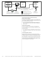
a) Maßnahmen bei räumlich weit verteilten Systeminstallationen
Bei räumlich weit verteilten Systeminstallationen, mit entsprechend
großen Potenzialunter schieden, wird der Aufbau lokaler Inseln und
die Verbindung dieser Inseln über kommerziell erhältliche elektro-
optische Signaltrenner empfohlen. Mit dieser Maßnahme wird ein
Höchstmaß an Robustheit gegenüber elektromagnetischen Störun-
gen erreicht, bei gleichzeitiger Ein haltung sämtlicher Anforderungen
der EN 60950-1. Fig. 4 zeigt die Wirkungsweise dieser Maßnahme.
Abb. 4: Maßnahme: Einsatz elektro-optischer Signaltrenner/Fig. 4: Use of electro-optical signal converters
Durch den Einsatz der elektro-optischen Signaltrenner zwischen den
Inseln wird die Erdschleife aufgetrennt. Innerhalb der Inseln werden
durch einen tragfähigen Potenzialausgleich Ausgleichsströme auf
den Leitungsschirmen verhindert.
b) Maßnahmen bei kleinen Systeminstallationen
Bei kleineren Installationen mit nur geringen Potenzialunterschie-
den kann die isolierte Montage des TiM3xx und der Peripherie-
geräte eine hinreichende Lösung sein. Abb. 5, Seite 6 zeigt die
Wirkungsweise dieser Maßnahme.
Erdschleifen werden, selbst bei hohen Erdpotenzialdifferenzen wirk-
sam verhindert. Dadurch ießen keine Ausgleichsströme mehr über
die Leitungsschirme und Metallgehäuse.
Wichtig!
Die Stromversorgung für den TiM3xx sowie die angeschlossene
Peripherie müssen dann ebenfalls die erforderliche Isolation sicher-
stellen. Unter Umständen kann zwischen den isoliert montierten
Metallgehäusen und dem örtli chen Erdpotenzial ein berührbares
Potenzial entstehen.
To g. 3. Due to different ground potentials of the devices in a
distributed system, high currents can occur in the cable shields and
damage or irreparably damage them. Due to insufcient ground po-
tential equalization, voltage differences arise between the ground-
ing points 1 and 2. The current loop closes via the shielded cables
and housing.
7.2 Remedial measures
The most common solution to prevent potential equalization
currents on cable shields is to ensure low-impedance and stable
current carrying equipotential bonding. If this is not possible the
following two solution approaches serve as a suggestion.
Important!
It is not advisable to open up the cable shields. As doing this means
that the EMC limit values can no longer be complied with.
a) Measures for widely distributed system installations
On widely distributed system installations with correspondingly large
potential differences, we recommend setting up local islands and
connecting them using commercially available electro-optical signal
converters. This measure achieves a high degree of resistance to
electromagnetic interference while at the same time complying
with all the requirements of EN 60950-1. Fig. 4 shows the function
of this measure.
The ground loop is opened by using the electro-optical signal
converters between the islands. Within the local islands, a stable
equipotential bonding prevents equalizing currents from occurring
at the cable shields.
b) Measures for small system installations
For smaller installations with small potential differences, the insu-
lated installation of the TiM3xx and peripheral devices can be a suf-
cient solution. Fig. 5, Page 6 shows the function of this measure.
Ground loops are, even in the event of large differences in the
ground potential, effectively prevented. Meaning that equalizing
currents cannot occur anymore via the cable shield and the metal
housing.
Important!
The power supply of the TiM3xx and the connected peripheral
devices must also guarantee the required level of insulation. Under
certain circumstances, a tangible potential can develop between
the insulated metal housings and the local ground potential.

6 # 8 8014595/YTX0/2016-03© SICK AG · Germany · All rights reserved · Subject to change without notice · Irrtümer und Änderungen vorbehalten
Abb. 5: Maßnahme: Isolierte Montage der Sensoren und der Peripheriegeräte/Fig. 5: Insulated assembly of the sensors and peripheral devices
Special national regulations for Sweden and Norway
Sweden: Varning och åtjärder
Utrustning som är kopplad till skyddsjord via jordat vägguttag och/
eller via annan utrustning och samtidigt är kopplad till kabel-TV nät
kan i vissa fall medfora risk for brand.
For att undvika detta skall vid anslutning av utrustningen till
kabel-TV nät galvanisk iso lator nnas mellan utrustningen och
kabel-TV nätet.
Norway: Advarsel og tiltaker
Utstyr som er koplet til beskyttelsesjord via nettplugg og/eller
via annet jordtilkoplet utstyr - og er tilkoplet et kabel-TV nett, kan
forårsake brannfare.
For å unngå dette skal det ved tilkopling av utstyret til kabel-TV
nettet installeres en gal vanisk isolator mellom utstyret og kabel-
TV nettet.
Corresponding English translation
Devices which are connected to the electrical system PE of the
building via a mains connection or other devices with a connection
to the PE, and which are connected to a cable distribution system
with coaxial cables, can under certain circumstances cause a risk
of re. Connections to a cable distribution system must therefore
be made such that electrical insulation is offered below a certain
frequency range (galvanic separating link).
TiM3xx
Erdungspunkt 2
grounding point 2
Erdungspunkt 3
grounding point 3
Erdungspunkt 1
grounding point 1
Erdpotenzialdifferenz/grounding potential difference
Ansteuerung für
Schalteingänge
Trigger for
switching inputs
Aktoren für
Schaltausgänge
Actuators for
switching outputs
Strom-
versorgung
Power supply
unit
U
CDB730-001
= Metallgehäuse/metal housing
= Kunststoffgehäuse/plastic housing
= geschirmte elektrische Leitung/
shielded electrical cable
Isolierte Montage/
electrically insulated

7 # 88014595/YTX0/2016-03 © SICK AG · Germany · All rights reserved · Subject to change without notice · Irrtümer und Änderungen vorbehalten
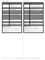
8. Technische Daten
Typ CDB730-001 (Artikel-Nr. 1055981)
Optische Anzeigen 5 x LED
Elektrische Anschlüsse Dose, D-Sub-HD, 15-pol.
Federkraftklemmen:
8 für Adern 0,14 mm
2
...2,5 mm
2
24 für Adern 0,14 mm
2
... 1 mm
2
Leitungsverschraubungen 4 x M16, Klemmbereich ∅ 4,5 ... 10 (7) mm
Versorgungsspannung DC 9 V ... 28 V für TiM3xx, SELV bzw.
PELV nach IEC 60364-4-41
Eigenleistungsaufnahme < 0,5 W
Eingangsstrom Max. 2,4 A (an Anschlussklemme U
IN
)
Sicherung Glasrohrsicherung 0,8 A träge für U
IN
*
1)
Gehäuse/Farbe Polycarbonat/Grundteil lichtblau (nach RAL
5012), Deckel neutral/teildurchsichtig
Prüfzeichen CE
Sicherheit Nach EN 60950-1: 2006-04/A11: 2009-03
2)
Schutzklasse III, nach EN 61140: 2007-03
Schutzart IP 65
3)
, nach EN 60529: 1999-10
EMV-Prüfung Störaussendung: nach EN 61000-6-3: 2007-
01/ A1: 2011-03
Störfestigkeit: nach EN 61000-6-2: 2005-08
Gewicht Ca. 240 g
Umgebungstemperatur Betrieb: –35 °C
4)
... +40 °C
Lager: –35 °C ... +70 °C
Rel. Luftfeuchtigkeit Max. 90 %, nicht kondensierend
1) Geschaltet über S 1.
2) Siehe auch Kapitel 7, Seite 4.
3) Mit SICK Standardleitung für Sensoren.
4) Betriebsumgebungstemperatur 0 °C bis –35 °C bei folgenden Bedingungen:
– Montage, elektrischer Anschluss sowie Konguration/Power-up des Moduls über
eingebaute Schalter nur im normalen Betriebsumgebungtemperaturbereich
0 °C bis +40 °C.
– Einsatz nur im Zustand der Ruhe (keine Montage-, Anschluss- oder Kongura-
tionsarbeiten am Modul).
8. Technical Data
Type CDB730-001 (Part no. 1055981)
Visual indicators 5 x LEDs
Electrical connections Female connector, D-Sub HD, 15-pin
Spring terminals: 8 for cores 0.14 mm
2
to
2.5 mm
2
(approx. 26 to 13 AWG) and 24 for cores
0.14 mm
2
to 1 mm
2
(approx. 26 to 17 AWG)
Cable glands 4 x M16, for cables ∅ 4.5 mm to 10 (7) mm
Power supply 9 V to 28 V DC for TiM3xx, SELV respectively PELV
accord. to IEC 60364-4-41
Power consumption < 0.5 W (internal)
Input current Max. 2.4 A (on terminals U
IN
)
Fuse Glass tube fuse 0.8 A, slow blow, for U
IN
*
1)
Housing/Color Polycarbonate/basic light blue (accord. to RAL
5012), cover neutral/partially transparent
Conformity CE
Safety Acc. to EN 60950-1: 2006-04/A11: 2009-03
2)
Protection class III, according to EN 61140: 2007-03
Enclosure rating IP 65
3)
, according to EN 60529: 1999-10
EMC tested Emission: according to EN 61000-6-3: 2007-01/
A1: 2011-03
Immunity: according to EN 61000-6-2: 2005-08
Weight Approx. 240 g
Ambient Operation: –35 °C
4)
to +40 °C
temperature Storage: –35 °C to +70 °C
Rel. air humidity Max. 90%, non-condensing
1) Switched via S 1.
2) See also chapter 7, page 4.
3) With SICK standard sensor cable.
4) Temperature range 0 °C to –35 °C at the following conditions:
– Installation, electrical connection as well as conguration/power-up of the
module using built-in switches only at normal operation ambient temperature
range of 0 °C to +40 °C.
– Application of the module only in rest status (without any mounting, electrical
installation or conguration works on the module).

SICK AG | Waldkirch | Germany | www.sick.com
8014595/YTX0/2016-03 ∙ TM_8M ∙ A4 4c int44
More representatives and agencies
at www.sick.com
Australia
Phone +61 3 9457 0600
1800 334 802 – tollfree
E-Mail [email protected]
Austria
Phone +43 (0)22 36 62 28 8-0
E-Mail of[email protected]
Belgium/Luxembourg
Phone +32 (0)2 466 55 66
E-Mail [email protected]
Brazil
Phone +55 11 3215-4900
E-Mail [email protected]
Canada
Phone +1 905 771 14 44
E-Mail [email protected]
Czech Republic
Phone +420 2 57 91 18 50
E-Mail [email protected]
Chile
Phone +56 2 2274 7430
E-Mail info@schadler.com
China
Phone +86 4000 121 000
E-Mail [email protected]
Denmark
Phone +45 45 82 64 00
E-Mail [email protected]
Finland
Phone +358-9-2515 800
E-Mail [email protected]
France
Phone +33 1 64 62 35 00
E-Mail [email protected]
Gemany
Phone +49 211 5301-301
E-Mail [email protected]
Great Britain
Phone +44 (0)1727 831121
E-Mail [email protected]
Hong Kong
Phone +852 2153 6300
E-Mail [email protected]
Hungary
Phone +36 1 371 2680
E-Mail of[email protected]
India
Phone +91–22–4033 8333
E-Mail [email protected]
Israel
Phone +972-4-6881000
E-Mail [email protected]
Italy
Phone +39 02 27 43 41
E-Mail [email protected]
Japan
Phone +81 (0)3 5309 2112
E-Mail suppor[email protected]
Malaysia
Phone +603 808070425
E-Mail enquiry.m[email protected]
Netherlands
Phone +31 (0)30 229 25 44
E-Mail [email protected]
New Zealand
Phone +64 9 415 0459
0800 222 278 – tollfree
E-Mail [email protected]
Norway
Phone +47 67 81 50 00
E-Mail [email protected]
Poland
Phone +48 22 837 40 50
E-Mail [email protected]
Romania
Phone +40 356 171 120
E-Mail of[email protected]
Russia
Phone +7-495-775-05-30
E-Mail [email protected]
Singapore
Phone +65 6744 3732
E-Mail [email protected]
Slovakia
Phone +421 482 901201
E-Mail [email protected]
Slovenia
Phone +386 (0)1-47 69 990
E-Mail of[email protected]
South Africa
Phone +27 11 472 3733
E-Mail [email protected]
South Korea
Phone +82 2 786 6321
E-Mail info@sickkorea.net
Spain
Phone +34 93 480 31 00
E-Mail [email protected]
Sweden
Phone +46 10 110 10 00
E-Mail [email protected]
Switzerland
Phone +41 41 619 29 39
E-Mail [email protected]
Taiwan
Phone +886 2 2375-6288
E-Mail [email protected]
Thailand
Phone +66 2645 0009
E-Mail [email protected]
Turkey
Phone +90 (216) 528 50 00
E-Mail [email protected]
United Arab Emirates
Phone +971 (0) 4 88 65 878
E-Mail [email protected]
USA/Mexico
Phone +1(952) 941-6780
1 (800) 325-7425 – tollfree
E-Mail [email protected]
Vietnam
Phone +84 8 62920204
E-Mail Ngo.Duy.Linh@sicksgp.com.sg
-
 1
1
-
 2
2
-
 3
3
-
 4
4
-
 5
5
-
 6
6
-
 7
7
-
 8
8


SICK CDB730-001 Connection Modula for TiM3xx Laser Scanner Bedienungsanleitung
- Typ
- Bedienungsanleitung
in anderen Sprachen
Verwandte Artikel
-
SICK CDB620 Connection Module Bedienungsanleitung
-
-
-
-
-
-
-
-
-