SICK CDM420-0001 Connection Module Bedienungsanleitung
- Typ
- Bedienungsanleitung

1 # 88010004/YTW9/2016-03 © SICK AG · Germany · All rights reserved · Subject to change without notice · Irrtümer und Änderungen vorbehalten
CDM420-0001
1. Bestimmungsgemäße Verwendung
■Modular aufgebautes Anschlussmodul (im Folgenden CDM420
genannt) zum Anschluss eines SICK-Identikationssensors (im
Folgenden ID-Sensor genannt) an Host (seriell), CAN-Sensor-Netz-
werk, Feldbussysteme sowie an Peripherie und Stromversor-
gung. Der ID-Sensor ist hierzu mit einer SICK-Standardleitung
an der außen zugänglichen 15-pol. D-Sub-Dose des CDM420
anzuschließen. Über Leitungsverschraubungen und Anschluss-
klemmen werden die Stromversorgung zugeführt und Signale auf
Leitungen verteilt. Optionaler Feldbusanschluss (Gateway) über
systemabhängige Steckverbindungen auf der Frontblende. Eine
ggf. im ID-Sensor integrierte Ethernet-Schnittstelle wird nicht über
das CDM420 angeschlossen.
■Unterstützte ID-Sensoren
*)
: Barcodescanner CLV61x bis CLV65x,
kamerabasierter Codeleser Lector62x, RFID-Schreib-/Lesegeräte
RFH6xx (HF) und RFU62x (UHF), Handheldscanner IDM1xx und
IDM2xx
2. Eigenschaften
■Basisgerät zur optionalen Aufnahme folgender Module:
– Parameter-Cloning-Modul CMC600 für externe Speicherung der
Kongurationsparameter des ID-Sensors. Dient auch der Akti-
vierung von Betriebsarten sowie der Erweiterung des ID-Sen-
sors um jeweils 2 digitale Schaltein- und -ausgänge (bei CLV61x
bis CLV65x, Lector62x, RFH6xx und RFU62x)
– Display-Modul CMD400, eingebaut in Deckelvariante, zur Anzei-
ge von Leseergebnissen u. Lesediagnosedaten des ID-Sensors
– Feldbusmodul CMF400 zur Anbindung des ID-Sensors an PRO-
FIBUS-DP, DeviceNet™ oder Ethernet TCP/IP
– Power-Supply-Modul CMP400 zur Stromversorgung des ID-Sen-
sors aus einem Wechselstromnetz.
■9-pol. D-Sub-Stecker intern: Anschluss der Aux-Schnittstelle (seri-
ell RS-232) des ID-Sensors an PC (Konguration/Diagnose)
■Variante CDM420-0101: zusätzlich serielle Host- und Aux-Schnitt-
stellen über zwei 9-polige D-Sub-Dosen auf Frontblende
■Anschlussklemmen für serielle Host-Schnittstelle, CAN-Bus,
Schaltein- und -ausgänge, Stromversorgung, Abschirmung
■Durch Deckel sichtbar: LEDs zur Anzeige von aktiven Schaltein-
und -ausgängen sowie Stellungen der Kongurationsschalter
■Schutzart IP 65 (Variante CDM420-0101: IP 20)
■Betriebsumgebungstemperatur –35 °C bis +40 °C
■UL-zertiziert bei Verwendung eines Class-2-Netzteils
Betriebsanleitung Operating Instructions
1. Intended use
■Modular designed connection module (referred to as CDM420
below) for connecting one SICK identication sensor (referred to
as ID sensor below) to host (serial), CAN Sensor Network, eldbus
systems, as well as to the peripheral equipment and voltage
supply. Connect the ID sensor using a SICK standard cable to
the externally accessible 15-pin D-Sub female connector of the
CDM420. Via cable glands and terminals the voltage supply is
connected and signals are distributed to cables. Optional eldbus
connection (gateway) via system depending on plug-in connec-
tions on face plate (front). The CDM420 is not used to connect an
ID sensor with integrated Ethernet interface to the Ethernet.
■Supported ID sensors
*)
: CLV61x to CLV65x bar code scanners,
Lector62x image-based code reader, RFH6xx (HF) and RFU62x
(UHF) RFID write/read devices, as well as IDM1xx and IDM2xx
hand-held scanners
2. Features
■Basic device for integrating optionally the following modules:
– CMC600 parameter cloning module for saving the ID sensor’s
conguration parameters externally. Also for activation of
operating modes as well as for extension of the ID sensor with
each of two digital switching inputs and outputs (on CLV61x to
CLV65x, Lector62x, RFH6xx and RFU62x)
– CMD400 display module (installed in a cover variant) for dis-
playing the reading results and diagnosis data of the ID sensor
– CMF400 eldbus module for connecting the ID sensor to
PROFIBUS-DP, DeviceNet™ or Ethernet TCP/IP
– CMP400 power supply module for supplying power to the ID
sensor from an AC power line
■9-pin internal D-Sub male connector: for connecting the Aux inter-
face (serial RS 232) to a PC for conguring and diagnosing the ID
sensor
■CDM420-0101 variant: The serial host and Aux interfaces can
also be connected via two 9-pin D Sub female connector on face
plate
■Terminals for serial host interface, CAN bus, switching inputs and
outputs, voltage supply, and shield
■Externally visible LEDs for displaying active switching inputs and
outputs, as well as switch settings for module conguration
■Enclosure rating IP 65 (CDM420-0101 variant: IP 20)
■Operation ambient temperature –35 °C to +40 °C
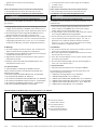
Anschlussmodul Connection Module
“Host“
V
S
“Sensor 2“
“Sensor 1“
“Result 1“
Licht-
schranke
(Lesetakt)
Photo reex
switch
(Reading clock)
Schalter/switch
Teach-in matchcode
“Aux“
PC
HOST
SPS/
PLC
ID
Sensor
CDM420-0001
. . . .
. . . . .
“CAN“
CAN bus
“Result 2“
*) Also suitable for CLV42x to CLV45x as well as ICR84x-2/ICR85x-2.
*) Auch geeignet für CLV42x bis CLV45x sowie ICR84x-2/ICR85x-2.

2 # 8 8010004/YTW9/2016-03© SICK AG · Germany · All rights reserved · Subject to change without notice · Irrtümer und Änderungen vorbehalten
(geprüft nach UL 1310) zur Stromversorgung
■Wartungsfrei
■UL certicated when a class 2 power supply unit according to
UL 1310 is used
■Maintenance-free
Feldbusmodul CMF400
CMF400 Fieldbus Module
Cloning-Modul CMC600
CMC600 Cloning Module
Power-Supply-Modul CMP400
CMP400 Power Supply Module
HINWEIS
Mögliche Funkstörungen beim Einsatz in Wohngebieten!
Das Anschlussmodul CDM420 ausschließlich in Industrieumgebun-
gen einsetzen.
NOTICE
RF interferences in case of use in residential areas!
The CDM420 Connection Module is excusively intended for use in
industrial areas.
Weitere Produktinformationen und EU-Konformitätserklärung:
Siehe Produktseite im Internet unter www.sick.com/cdm
Further Product Information and EU Conformity Declaration:
See product page on the Internet at www.sick.com/cdm
3. Voraussetzungen zur Installation und Inbetriebnahme 3. Installation and Commissioning Requirements
■Versorgungsspannung DC 10 V bis 30 V, abhängig vom ID-Sensor
und ggf. weiteren Modulen im CDM420. Siehe Übersicht in 6.2
Versorgungsspannung, Seite 3 und 8. Technische Daten, Seite 7.
■Bei Verwendung des Power-Supply-Moduls CMP400 eine Ein-
gangsspannung AC 100 V bis 250 V, 50 Hz bis 60 Hz
■Montage-, Anschluss- und Kongurationsarbeiten nur im Umge-
bungstemperaturbereich 0°C bis +40 °C vornehmen! Einsatz im
Umgebungstemperaturbereich 0°C bis –35 °C nur im Zustand
der Ruhe (keine Montage-, Anschluss-, Kongurationsarbeiten).
4. Montage
■Stets freier Zugang zum internen Stecker „AUX“ erforderlich für
Zugriff auf den ID-Sensor (Konguration und Diagnose)
■Leitungslänge zwischen CDM420 und ID-Sensor bei Nutzung der
seriellen Datenschnittstellen: max. 10 m
■Abgenommener Deckel mit Anschlussbild um 180° gedreht in
Parkposition arretierbar
Bohrungs- und Gehäusemaße siehe Maßbild (Seite 8), max.
Schraubendurchmesser 4 mm.
4.1 Optionale Module
Optionale Module vor Montage des CDM420 einbauen.
Einbau und Inbetriebnahme siehe Betriebsanleitung (BA) bzw.
Montageanleitung (MA):
■BA „Parameterspeicher-Modul CMC600-101“ (Nr. 8015190)
■BA „Display-Modul CMD400“ (Nr. 8010372)
■BA „Feldbusmodul CMF400-1x01 (PROFIBUS-DP)“ (Nr. 8010461)
■BA „Feldbusmodul CMF400-2101 (DeviceNet™)“ (Nr. 8010463)
■BA „Feldbusmodul CMF400-3101 (Ethernet)“ (Nr. 8010734)
■MA „Power-Supply-Modul CMP400“ (Nr. 8010365)
■10 V to 30 V DC voltage supply, depending on ID sensor and
further modules in the CDM420. See overview in 6.2 Supply
voltage, Page 3 and 8. Technical Data, Page 7.
■An input voltage of 100 V to 250 V AC, 50 Hz to 60 Hz is required
when using the CMP400 Power Supply Module
■Perform mounting, electrical connection and conguration works
only at operation ambient temperature range 0° C to +40 °C!
Application of the module at operation ambient temperature
range 0° C to –35 °C only in rest status (without any mounting,
electrical installation or conguration works).
4. Installation
■Free access to internal “AUX” connector is required to connect to
the ID sensor (conguration and diagnosis)
■Max. cable length between CDM420 and ID sensors if the serial
data interfaces are used: 10 m
■Cover with connection diagram can be removed, rotated by 180°,
and locked in park position
See dimensional drawing (Page 8) for hole and housing dimen-
sions, max. screw diameter 4 mm.
4.1 Optional modules
Install the optional modules before mounting the CDM420.
For installing and commissioning see operating instructions (OI)
respectively tting instructions (FI):
■“CMC600-101 Cloning Module“ OI (no. 8015190)
■“CMD400 Display Module“ OI (no. 8010372)
■“CMF400-1x01 Fieldbus Mod. (PROFIBUS-DP)“ OI (no. 8010462)
■“CMF400-2101 Fieldbus Mod. (DeviceNet™)“ OI (no. 8010464)
■“CMF400-3101 Fieldbus Module (Ethernet)“ OI (no. 8010735)
■“CMP400 Power Supply Module“ FI (no. 8010365)
Modul-Steckplätze im CDM420/Plug-in slots of the modules in the CDM420:

3 # 88010004/YTW9/2016-03 © SICK AG · Germany · All rights reserved · Subject to change without notice · Irrtümer und Änderungen vorbehalten
6. Electrical Installation
6.1 Data interfaces
Recommended max. cable length from ID sensor to host:
5.2 Funktion der LEDs
LED Farbe Funktion
Power Grün Leuchtet, wenn die Versorgungsspannung am
CDM420 anliegt und Schalter S 1 auf „ON“
Sensor 1, 2 Gelb Leuchtet, wenn der entsprechende Eingang des
ID Sensors schaltet
Result 1, 2 Gelb Leuchtet, wenn der entsprechende Ausgang des
ID Sensors schaltet
6. Elektrische Installation
6.1 Datenschnittstellen
Empfohlene max. Leitungslänge des ID-Sensor zum Host:
5.2 LEDs function
LED Color Function
Power Green Lights up when the power supply is connected
to the CDM420 and switch S 1 is set to “ON“
Sensor 1, 2 Yellow Lights up when the corresponding input of the
ID sensor switches
Result 1, 2 Yellow Lights up when the corresponding output of the
ID sensor switches
Interface type Data transfer rate Distance to host
RS 232 Up to 19.2 kBd Max. 10 m
38.4 kBd ... 57.6 kBd Max. 3 m
RS 422/485 Max. 38.4 kBd Max. 1,200 m
Max. 57.6 kBd Max. 500 m
Schnittstellentyp Datenübertragungsrate Entfernung z. Host
RS-232 Bis 19,2 kBd Max. 10 m
38,4 kBd ... 57,6 kBd Max. 3 m
RS-422/485 Max. 38,4 kBd Max. 1.200 m
Max. 57,6 kBd Max. 500 m
5. Kongurationselemente und Anzeigen
5.1 Funktion der Kongurationsschalter
Schalter Funktion Default
S 1 (Power) Anliegende Versorgungsspannung: ON
ON: Versorgungsspannung ein
OFF: Versorgungsspannung aus
S 2 (RS-485) RS-422/485-Umschaltung: OFF
ON: RS-485
OFF: RS-422
S 3 (Trm422) RS-422-Terminierung (Empfänger): OFF
ON: Widerstand 120 Ohm zugeschaltet
OFF: Keine Terminierung
S 4 (TrmCAN) Terminierung des CAN-Busses: OFF
ON: Widerstand 120 Ohm zugeschaltet
OFF: Keine Terminierung
S 6 (SGND-GND) Bezugspotenzial für Sensor-GND: ON
ON: Verbunden mit GND des ID Sensors
OFF: Potenzialfrei
S 8 (CMC) Integration des CMC600: NO (oben)
„YES“: CMC in Leitung der Aux-Schnitt-
stelle des ID Sensors geschaltet
„NO“: Kein CMC gesteckt
Switch Function Default
S 1 (Power) Connected power supply: ON
ON: Power supply voltage on
OFF: Power supply voltage off
S 2 (RS 485) RS 422/485 selector: OFF
ON: RS 485
OFF: RS 422
S 3 (Trm422) RS 422 termination (receiver): OFF
ON: 120 Ohm resistor connected
OFF: No termination
S 4 (TrmCAN) CAN bus termination: OFF
ON: 120 Ohm resistor connected
OFF: No termination
S 6 (SGND-GND) Reference potential for sensor GND: ON
ON: Connected to GND of ID sensor
OFF: Floating
S 8 (CMC) CMC600 integration: NO (on top)
“YES”: CMC connected to Aux
interface of ID sensor
“NO”: CMC not connected
5. Conguration Elements and Displays
5.1 Conguration Switches
6.2 Versorgungsspannung
Die Höhe der erforderlichen Versorgungsspannung ist abhängig
vom anzuschließenden ID-Sensor und der optionalen Module:
6.2 Supply voltage
The required power supply voltage depends on the ID-sensor to be
connected and on the used optional modules:
Wichtig:
Die zusätzlichen Eingänge „Aux In 1 und 2“ sowie die Ausgänge
„Aux Out 1 und 2“ haben keine Statusanzeige durch LEDs.
Important:
The additional inputs “Aux In 1 and 2“ as well as the outputs “Aux
Out 1 and 2“ have no status indication by LEDs.
Siehe hierzu auch Angaben auf dem Typenschild des ID-Sensors. See also details on the typeplate of the ID sensor.
*) Nr. 2056475 (mit Leitung 0,2 m) oder Nr. 2057709 (mit Leitung 0,3 m). *) No. 2056475 (with cable 0.2 m) or no. 2057709 (with cable 0.3 m).
ID-Sensor / Modul Versorgungsspannung
CLV61x, CLV62x, Lector62x DC 10 V ... 30 V
CLV63x ... CLV65x ohne Heizung DC 18 V ... 30 V
CLV63x ... CLV65x mit Heizung DC 24 V ± 10 %
RFH6xx, RFU620-104xx DC 10 V ... 30 V
RFU620-101xx, bis –25 °C DC 10 V ... 30 V
RFU620-101xx, bei –25 °C ... –35 °C DC 20 V ... 30 V
CLV42x ... CLV45x, ICR85x-2 DC 10 V ... 30 V
ICR84x-2 DC 15 V ... 30 V
IDM1xx, IDM2xx DC 5 V, über DC 24 V/5 V-
Wandler
*)
Mit CMF400 oder CMD400 DC 18 V ... 30 V
ID sensor /Module Supply voltage
CLV61x, CLV62x, Lector62x 10 V to 30 V DC
CLV63x ... CLV65x without heater 18 V to 30 V DC
CLV63x ... CLV65x with heater 24 V DC ± 10 %
RFH6xx, RFU620-104xx 10 V to 30 V DC
RFU620-101xx, to –25 °C 10 V to 30 V DC
RFU620-101xx, from –25 °C to –35 °C 20 V to 30 V DC
CLV42x ... CLV45x, ICR85x-2 10 V to 30 V DC
ICR84x-2 15 V to 30 V DC
IDM1xx, IDM2xx 5 V DC, via 24 V DC/5 V DC
converter
*)
With CMF400 or CMD400 18 V to 30 V DC

4 # 8 8010004/YTW9/2016-03© SICK AG · Germany · All rights reserved · Subject to change without notice · Irrtümer und Änderungen vorbehalten
Wichtig:
Durch Verwendung des CMP400 verliert das Anschlussmodul und
der angeschlossene ID-Sensor die UL-Zertizierung.
6.3 Verdrahtung des CDM420
■Elektrische Verbindungen nur im spannungsfreien Zustand her-
stellen oder trennen.
■Für alle Anschlüsse an den Klemmleisten Kupferleitungen mit
einem Aderquerschnitt von mindestens 0,14 mm
2
verwenden
■Um den Kurzschluss- und Überlastungschutz der abgehenden
Versorgungsleitungen zum ID-Sensor sicherzustellen, müssen
die verwendeten Aderquerschnitte unter Berücksichtigung der
im CDM420 eingebauten Sicherung ausgelegt werden.
Folgende Normen sind zu beachten: DIN VDE 0100 (Teil 430),
DIN VDE 0298 (Teil 4) bzw. DIN VDE 0891 (Teil 1)
■Kundenseitige Abschirmung am CDM420 auegen (Kl. „Shield“)
■Klemmenbelegung siehe Anschlussbild, Seite 6 und im Deckel
innen. Anschlusspläne für Host-/CAN-Schnittstelle/Schaltein- und
-ausgänge siehe Stromlaufplan (Seite 5)
■Variante CDM420-0101: Pinbelegung für zusätzliche 9-pol.
D-Sub-Dosen (serielle Host- und Aux-Schnittstelle) siehe Seite 5
■Host-Schnittstelle EMV-gerecht über abgeschirmte Leitungen an
den Host anschließen.
■Um Störeinüsse zu vermeiden, Leitungen möglichst nicht paral-
lel zu Stromversorgungs- und Motorleitungen verlegen
■Bezugspotenzial für die Schalteingänge mit Schalter S 6 wählen
Vorgehensweise:
1. Leitung des ID-Sensors an die 15-pol. D-Sub-HD-Dose des
CDM420 anschließen. Für die M12-Anschlussvariante des ID-
Sensors folgende Adapterleitung verwenden:
– M12, 12-pol. auf D-Sub-HD, 15-pol., z. B. 2041834 (2 m)
– M12, 17-pol. auf D-Sub-HD, 15-pol., z. B. 2055419 (2 m)
2. Alle anderen Leitungen über Leitungsverschraubungen an An-
schlussklemmen auegen. Um die Schutzart IP 65 zu erhalten,
nicht verwendete Durchführungen mit Blindstopfen versehen.
3. CAN-Bus: Falls CDM420 am Bussende, Terminierungswiderstand
mit Schalter S 4 zuschalten
4. Mit Kongurationssoftware SOPAS-ET
*)
den Treiber für verdrahte-
te serielle Host- und/oder CAN-Schnittstelle im ID-Sensor aktivie-
ren:
– Hierzu PC mit 3-adriger RS-232-Datenleitung (Nullmodemlei-
tung) an 9-pol. Stecker „AUX“ im CDM420 anschließen
Important:
Using the CMP400, the UL certication for the connection module
and the connected ID sensor is not longer valid.
6.3 CDM420 wiring
■Connect or release current linkages only under de-energized
conditions.
■Use copper cables with a minimum wire cross-section of
0.14 mm
2
(26 AWG) for all connections at the terminal strips.
■To ensure that the outgoing supply cables to the ID sensor are
protected against short-circuits and overload, the wire cross-sec-
tions must be dimensioned in accordance with the fuse installed
in the CDM420. The valid national standards must be observed.
■Connect the shield of your system to the CDM420 (“Shield“
terminal)
■For terminal assignment, see connection diagram on Page 6 or
inside the cover. For host/CAN interface/switching input and
output diagrams, see circuit diagram (Page 5).
■CDM420-0101 variant: for pin assignment of the additional 9-pin
D Sub female connector (serial Host and Aux interface), see Page
5.
■Use shielded cables to establish an EMC-compatible connection
between host interface and host.
■To prevent interference, do not install cables parallel to power
supply or motor cables (e.g. cable ducts).
■Choose reference potential for switching inputs with switch S 6.
Electrical Installation Procedure:
1. Connect the ID sensor cable to the 15-pin D-Sub HD female
connector on the CDM420. For M12 connector version of the ID
sensor use the following adapter cable:
– M12, 12-pin to D-Sub-HD, 15-pin, e.g. 2041834 (2 m)
– M12, 17-pin to D-Sub-HD, 15-pin, e.g. 2055419 (2 m)
2. Connect all other cables to the terminals. To remain enclosure
rating IP 65, use blanking plugs to close any unused bushings.
3. CAN bus: if CDM420 is integrated at bus end, enable termination
resistor with switch S 4.
4. Using the SOPAS ET
*)
conguration software, activate the driver
for the connected serial host and/or CAN interface in the ID sen-
sor:
– Connect the PC to the 9-pin “AUX” male connector inside the
CDM420 using a 3-core RS 232 data cable (null modem cable)
– CDM420-0101 variant: connect the PC alternatively to the
Power-Supply-Modul CMP400 (AC/DC):
GEFAHR
Verletzungsgefahr durch elektrischen Strom!
Das Modul CMP400 wird an Wechselspannung
AC 100 bis 250 V, 50 bis 60 Hz angeschlossen.
Anschluss nur durch ausreichend qualiziertes Fachpersonal
durchführen lassen.
Sicherheithinweise in der Montageanleitung des CMP400
(Nr. 8010365) beachten.
Schutzleiter an Klemme PE anschließen.
CMP400 Power Supply Module (AC/DC):
DANGER
Risk of injuries due to electrical current!
The CMP400 power supply module is connected to a
mains voltage of 100 to 250 V AC, 50 Hz to 60 Hz.
The module should only be connected by sufciently qualied
personnel.
Observe the safety information in the CMP400 Fitting Instruc-
tions (no. 8010365).
Connect the protective conductor to the “PE“ terminal.
Verletzungsgefahr durch elektrischen Strom!
Nur ein Netzteil verwenden, dessen Ausgangskreis gegenüber dem
Eingangskreis eine sichere elektrische Trennung besitzt.
Beispielsweise durch einen Sicherheitstrafo gemäß EN 61558-1.
Risk of injuries due to electrical current!
Only use a power supply unit whose output circuit is safely electri-
cally isolated from the input circuit by means of a safety isolating
transformer according to EN 61558-1, for example.
GEFAHR DANGER

5 # 88010004/YTW9/2016-03 © SICK AG · Germany · All rights reserved · Subject to change without notice · Irrtümer und Änderungen vorbehalten
– Variante CDM420-0101: PC alternativ mit 3-adr. RS-232-Daten-
leitung (1:1) an 9-pol. Dose „AUX“ auf Frontplatte anschließen.
– Oder ID-Sensor über Ethernet kontaktieren (abhängig vom
Sensortyp).
5. Stromversorgung für CDM420 einschalten.
*) CLV-Setup für CLV42x to CLV45x sowie ICR84x-2/ICR85x-2.
9-pin “AUX” female connector on the face plate using a 3-core
RS 232 data cable (1:1).
– Or establish communication to the ID sensor via Ethernet (de-
pends on type)
5. Switch on the voltage supply for CDM420.
*) CLV-Setup for CLV42x to CLV45x as well as ICR84x-2/ICR85x-2.
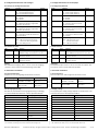
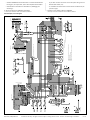
Stromlaufplan/circuit diagram
V1: CDM420 for CLV42x / CLV43x / 44x /45x / ICR84x / ICR85x
V2: CDM410 for CLV41x
V3: CDM490 for CLV49x / LMS400
V4: CDM4xx for operation with CMX module for CAN multiplexer
S4: Switch for CAN termination
S5: Switch for CAN_2 termination
S3: Switch for RS485 termination
S2: Switch RS422 <—> RS485
S6: Switch INGND — GND
4-pin to I/O board
4-pin to CMP
to CMF400 bus module
+24V_Heating_Out
+24V_Heating_Out
to CMC module
AUX plug
S7: Switch RS232 CLV41x: Terminal <—> AUX
15-pin D-Sub HD socket to scanner
For MPX module
(no scanner connected)

6 # 88010004/YTW9/2016-03 © SICK AG · Germany · All rights reserved · Subject to change without notice · Irrtümer und Änderungen vorbehalten
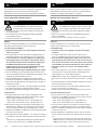
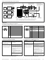
Aufbau, Klemmenbelegung/design, terminal assignment
CDM420-0101:
Pinbelegung der 9-pol. D-Sub-Dosen auf Frontblende
Pin assignment of 9-pin D Sub female connectors on face plate (front)
Schema: Aufbau eines SICK CAN-Sensor-Netzwerkes
Diagram: Building a SICK CAN Sensor Network
Kongurationsschalter
Conguration switches
Anschluss ID-Sensor
ID sensor connection
Klemmleisten ID-Sensor
Terminal strips for ID sensor
Anschluss PC
PC connection
Kongurationsschalter
Conguration switches
Klemmleisten für
Versorgungsspannung
Terminal strips for power
supply voltage
Pin Signal
1 Not connected
2 TxD (RS 232), AUX
3 RxD (RS 232), AUX
4 Not connected
5 GND
6 Not connected
7 Not connected
8 Not connected
9 Not connected
AUX
15
69
Pin Signal Color (internal)
1 Not connected –
2 TxD (RS 232), Weiß/White
TD– (RS 422)
3 RxD (RS 232), Grün/Green
RD– (RS 422)
4 Not connected –
5 GND Brown/Brown
6 TD+ (RS 422) Gelb/Yellow
7 Not connected –
8 RD+ (RS 422) Grau/Grey
9 Not connected –
15
69
HOST
LEDs
CAN bus
“Host“
“Result 1“
“Sensor 1“
ID sensor
ID sensor
ID sensor
CDM420
CDM420
CDM420
+24 V* = Versorgungspannung +24 V nach Schalter S1 und Sicherung 0,8 A.
+24 V* = Power supply voltage +24 V behind switch S1 and fuse 0.8 A
7. Fehlersuche für Basisgerät CDM420
7. Troubleshooting for CDM420 (Basic Device)
Störung
• Nach Anlegen der Versorgungs-
spannung U
IN
leuchtet die LED
„Power“ (U
IN
*) nicht
• Nach Anschluss des PCs an
den Stecker „AUX“ kein Zugriff
auf den ID-Sensor mit Kongu-
rationssoftware SOPAS-ET
*)
Abhilfe
• Schalter S 1 (Power) in Position
„ON“ bringen
• Wenn kein CMC600 gesteckt, Schal-
ter S 8 in Position „NO“ bringen
• SOPAS-ET
*)
: Erforderliche Gerätebe-
schreibungsdatei für betreffenden
ID-Sensor nicht vorhanden oder für
anderen Firmwarestand als vorlie-
gendes Gerät.
Passende Gerätebeschreibungs-
datei in SOPAS-ET über Funktion
„Gerätemanager“ nachladen und
einbinden.
• SOPAS-ET
*)
: Mit Funktion „Geräte-
suche“ die Kommunikation mit dem
ID-Sensor aufnehmen
*) CLV-Setup für CLV42x bis CLV45x sowie ICR84x-2/ICR85x-2. *) CLV-Setup for CLV42x to CLV45x, as well as ICR84x-2/85x-2.
Remedy
• Set switch S 1 (Power) to “ON”
• If no CMC600 is connected, set
switch S 8 to “NO”
• SOPAS-ET
*)
: required device
descrciption le for the related ID
sensor not existent or le related
to an other rmware version as the
current device used.
Reload and insert the suitable
device descrciption le in SOPAS-
ET using the “Device manager”
function.
• SOPAS-ET
*)
: Using the “Device
search” function to start the com-
munication with the ID sensor
Malfunction
• “Power” LED (U
IN
*) does not
light up when power supply U
IN
is connected
• Cannot access ID sensor with
SOPAS-ET
*)
conguration soft-
ware after connecting the PC to
the “AUX” male connector

7 # 88010004/YTW9/2016-03 © SICK AG · Germany · All rights reserved · Subject to change without notice · Irrtümer und Änderungen vorbehalten
8. Technische Daten
Typ CDM420-0001 (Nr. 1025362)
Optische Anzeigen 5 x LED
Elektrische Anschlüsse 1 x Dose, D-Sub-HD, 15-pol.
1 x Stecker, D-Sub, 9-pol.
Schraubklemmen, für Adern 0,14 ... 2,5 mm
2
Federkraftklemmen, für Adern 0,14...1 mm
2
Leitungsverschraubungen 6 x M16, für Leitungen ∅ 4,5 mm ... 10 mm
Versorgungsspannung DC 10 V ... 30 V, SELV bzw. PELV nach IEC
60364-4-41.
DC 18 V ... 30 V bei Verwendung des
Display-Moduls CMD400 und/oder
eines Feldbusmoduls CMF400.
Verwendung eines Netzteils gemäß Class 2
(UL1310)
Leistungsdurchuss
1)
P
ID-Sensor
+ Eigenleistungsaufnahme 0,5 W
Sicherung
2)
Glasrohrsicherung 0,8 A träge
Gehäuse / Farbe Polycarbonat / Blau, Deckel transparent
Prüfzeichen CE, UL
3)
Schutzklasse III
4)
, nach EN 61140
Schutzart IP 65
5)
, nach EN 60529
EMV-Prüfung Störaussendung: nach EN 61000-6-4: 2007-
01), A1: 2011-02
Störfestigkeit EN 61000-6-2: 2005-08
Schwingfestigkeit Nach IEC 60068-2-27: 2009-05
Schockfestigkeit Nach IEC 60068-2-6: 2008-02
Gewicht (Basisgerät) Ca. 800 g
Umgebungstemperatur Betrieb: –35
6)
°C ... +40 °C
Lager: –35 °C ... +70 °C
Rel. Luftfeuchtigkeit Max. 90 %, nicht kondensierend
1) Abhängig vom ID-Sensor, ohne Display-Modul, Parameterspeicher-Modul oder
Feldbusmodul.
2) Für Spannung +24 V*, geschaltet über S1 und interne Sicherung.
3) Gültig bei entsprechender Gerätekennzeichnung auf dem Typenschild.
4) Klasse I mit Power-Supply-Modul CMP400 und angeschlossenem PE-Leiter.
5) Bei Verwendung der SICK Standardanschlussleitung und geschlossener Frontblen-
de des CDM420 (Blindplatte ohne Anschlüsse oder Platte mit IP-65-Anschluss).
6) In Ruhe (keine Montage oder elektrische Installation), sonst bis –20 °C.
8. Technical Data
Type CDM420-0001 (no. 1025362)
Visual indicators 5 x LEDs
Electrical connections 1 x female connector, D-Sub HD, 15-pin
1 x male connector D-Sub, 9-pin
Screw terminals, for cores 0.14 mm
2
... 2.5 mm
2
(approx. 26 AWG ... 13 AWG)
Spring terminals, for cores 0.14 mm
2
... 1 mm
2
(approx. 26 AWG ... 17 AWG)
Cable glands 6 x M16, for cables diameter 4.5 mm ... 10 mm
Power supply 10 V ... 30 V DC SELV respectively PELV to
IEC 60364-4-41.
18 V ... 30 V DC when using the CMD400 display
module and/or a CMF400 eldbus module.
Use a power supply unit according to Class 2
(UL1310)
Power down stream
1)
P
ID sensor
+ internal power consumption 0.5 W
Fuse
2)
Glass tube fuse 0.8 A, type slow-blow
Housing / Color Polycarbonate / Blue, transparent cover
Conformity CE, UL
3)
Protection class III
4)
, according to EN 61140
Enclosure rating IP 65
5)
, according to EN 60529
EMC tested Emission: according to EN 61000-6-4: 2007-
01, A1: 2011-02
Immunity: according to EN 61000-6-2: 2005-08
Vibration tested According to IEC 60068-2-27: 2009-05
Shock tested According to IEC 60068-2-6: 2008-02
Weight (basic device) Approx. 800 g
Ambient temperature Operation: –35
6)
°C ... +40 °C
Storage: –35 °C ... +70 °C
Rel. air humidity Max. 90 %, non-condensing
1) ID-Sensor type specic, without display module, parameter cloning module, or
eldbus module.
2) For voltage +24 V*, switched via S 1 and internal fuse.
3) Valid with corresponding product marking on the typeplate.
4) Class I with CMP400 power supply module and connected PE conductor.
5) With SICK standard cable and closed face plate (dummy plate without connections
or plate with IP 65 connectors) on the CDM420.
6) Without any mounting or electrical installation work, otherwise –20 °C.
Wichtig:
Fehlersuche in Zusammenhang mit optionalen Modulen siehe
jeweils deren Betriebs- oder Montageanleitung.
Important:
For troubleshooting of the optional modules see the respective
operating or tting instructions.
*) CLV-Setup für CLV42x bis CLV45x sowie ICR84x-2/ICR85x-2.
Störung
• Signale des angeschlossenen
Lesetakt-Sensors bleiben
wirkungslos im ID-Sensor
Abhilfe
• Lesetakt-Sensor gemäß Betriebsan-
leitung des ID-Sensors anschließen
• Stellung des Schalters S 6 prüfen
(SGND–GND)
• Mit SOPAS-ET
*)
die Quelle des
Lesetakts im ID-Sensor auf „Sensor
1“ einstellen.
Download zum ID-Sensor durchfüh-
ren!
*) CLV-Setup for CLV42x to CLV45x as well as ICR84x-2/ICR85x-2.
Remedy
• Connect reading pulse sensor in
accordance with the operating
instructions of the ID sensor
• Check switch S 6 (SGND–GND)
• Using SOPAS-ET
*)
software, set
the reading pulse source on the ID
sensor to “Sensor 1”.
Perform a download to the ID
sensor.
Malfunction
• Signals from connected reading
pulse sensor have no effect to
the ID sensor

8 # 8 8010004/YTW9/2016-03© SICK AG · Germany · All rights reserved · Subject to change without notice · Irrtümer und Änderungen vorbehalten
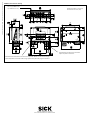
Maßbild/dimensioned drawing
Alle Abmessungen in mm (inch)
All dimensions in mm (inch)
Nur bei Typ CDM420-0101
Type CDM420-0101 only
Erforderlicher Anschlussraum für Stecker
Space required for connector
Erforderlicher Anschlussraum für Stecker bei optionaler Blende mit Steckverbindungen
Space required for connectors when using optional face plate with plug-in connections
8010004/YTW9/2016-03 · TM_8M · Printed in Germany
· Subject to change without notice
SICK AG · Waldkirch · Germany
For local sales ofces see www.sick.com
-
 1
1
-
 2
2
-
 3
3
-
 4
4
-
 5
5
-
 6
6
-
 7
7
-
 8
8


SICK CDM420-0001 Connection Module Bedienungsanleitung
- Typ
- Bedienungsanleitung
in anderen Sprachen
Verwandte Artikel
-
SICK CDM420-0004 Connection Module Bedienungsanleitung
-
-
-
-
-
-
-
-
-