
© SICK AG · Division Auto Ident · Germany · All rights reserved 1 # 48010000/TF10/2009-08
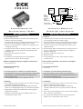
CDB410
1. Produkteigenschaften
■ Kleines Anschlussmodul zum Anschluss eines CLV41x an Host,
Peripherie und Stromversorgung
■ 9-pol. D-Sub-Stecker intern, für Anschluss der Hostschnittstelle 2
(RS-232) an PC zur Konfiguration/Diagnose des CLV41x
■ Klemmen für Hostschnittstelle, Schaltein- und -ausgänge, Strom-
versorgung, Schirmung
■ Von außen sichtbar: LEDs zur Anzeige von aktiven Schaltein- und
-ausgängen sowie Schalterstellungen der Modulkonfiguration
■ Schutzart IP 65
■ Montierbar bei geschlossenem Deckel
■ Wartungsfrei
■ UL-zertifiziert bei Verwendung eines Class 2-Netzgerätes
(geprüft nach UL 1310) zur Stromversorgung
Weitere Produktinformationen, Programm „CLV-Connect“:
¾ Siehe www.sick.com
EG-Konformitätserklärung:
¾ Auf Anforderung
2. Voraussetzungen zur Installation und Inbetriebnahme
■ Anschlusspläne in CLV-Connect (auf CD „Manuals & Software Bar
Code Scanners“, die dem Barcodescanner beiliegt, oder via
Internet www.sick.com)
■ Versorgungsspannung DC 24 V, erzeugt nach IEC 742
3. Montage
■ Freier Zugang zum internen Stecker „AUX“ erforderlich für Zugriff
auf CLV41x (Konfiguration/Diagnose)
■ Maximale Leitungslänge zwischen CDB410 und CLV41x beim
Einsatz von Verlängerungsleitungen: 10 m (RS-232-Schnittstelle!)
■ Abgenommener Deckel mit Anschlussbild um 180° gedreht in
Parkposition arretierbar
¾ Bohrungs- und Gehäusemaße siehe Maßbild (Seite 4), max.
Schraubendurchmesser 4 mm.
Anschlussmodul für
Barcodescanner CLV41x
Connection Module for
CLV41x Bar Code Scanner
1. Features
■ Compact connection module for connecting a CLV41x to the
host, peripheral equipment, and power supply
■ 9-pin internal D-Sub connector for connecting the host interface
2 (RS 232) to a PC for configuring/troubleshooting the CLV41x
■ Terminals for host interface, switching inputs/outputs, power
supply, and shield
■ Externally visible LEDs for indicating active switching inputs and
outputs, as well as switch settings for module configuration
■ Enclosure rating IP 65
■ Installation possible with closed cover
■ Maintenance-free
■ UL certificated when a class 2 power supply according to
UL 1310 is used
Further Product Information, ”CLV-Connect” PC Program:
¾ See www.sick.com
EC Conformity Declaration:
¾ On request
2. Installation and Commissioning Requirements
■ Connection diagrams in CLV-Connect (on the “Manuals &
Software Bar Code Scanners“ CD, provided with the scanner or
from the Internet www.sick.com)
■ 24 V DC power supply generated in accordance with IEC 742
3. Installation
■ Free access to internal “AUX” connector is required for access to
CLV41x (configuration/troubleshooting)
■ Maximum cable length between CDB410 and CLV41x if
extension cables are used: 10 m (32.8 ft) because of RS 232
interface
■ Cover with connection diagram can be removed, rotated through
180°, and locked in park position
¾ See dimensioned drawing for hole and housing dimensions
(Page 4), max. screw diameter 4 mm (0.15 in).
BeBe
BeBe
Be
trtr
trtr
tr
iebsanleitungiebsanleitung
iebsanleitungiebsanleitung
iebsanleitung
OperOper
OperOper
Oper
ating Insating Ins
ating Insating Ins
ating Ins
trtr
trtr
tr
uctionsuctions
uctionsuctions
uctions
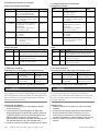
“Host“
6 to 30 V DC
“Sensor 2“
“Sensor 1“
“Result 1“
Licht-
schranke
(Lesetakt)
Photo reflex
switch
(Reading clock)
Schalter/switch
Teach-in matchcode
“Host2“
PC
HOST
SPS/PLC
CLV41x
CDB410
. . . .
. . . . .
AUX
“Result 2“
SPS/PLC
“Result 3“
SPS/PLC

2 # 4 © SICK AG · Division Auto Ident · Germany · All rights reserved 8010000/TF10/2009-08
Schnittstellentyp Datenübertragungsrate Entfernung z. Host
RS-232 bis 19,2 kBd max. 10 m
38,4 ... 57,6 kBd max. 3 m
RS-422 max. 38,4 kBd max. 1.200 m
max. 57,6 kBd max. 500 m
5. Elektrische Installation
Empfohlene max. Leitungslänge vom CLV41x zum Host:
Versorgungsspannung DC 24 V (gemäß IEC 60364-4-41):
Schalter Funktion Default
S 1 (Power) Anliegende Versorgungsspannung: ON
ON: Versorgungsspannung ein
OFF: Versorgungsspannung aus
S 3 (SGND-GND) Bezugspotenzial für Sensor-GND: ON
ON: verbunden mit GND d. CLV41x
OFF: potenzialfrei
S 5 (410:RS232) Verschaltung der Hostschnittstelle 2: HOSTÅ410
“HOSTÅ410“: vom CLV41x auf
Klemmenleiste
“RS232ÆAUX“: vom CLV41x auf
Service-Stecker „AUX“
S 6 (RS485) RS-422/485-Umschaltung OFF
ON: RS-485
OFF: RS-422
S 7 (Term422) RS-422-Terminierung (Empfänger) OFF
ON: Widerstand 120 Ohm zu-
geschaltet
OFF: keine Terminierung
Verdrahtung des CDB410:
■ Elektrische Verbindungen nur im spannungsfreien Zustand
herstellen oder lösen.
■ Um den Kurzschluss-/Überlastungschutz der abgehenden
Versorgungsleitungen zum CLV410 sicherzustellen, müssen die
verwendeten Aderquerschnitte unter Berücksichtigung der im
CDB410 eingebauten Sicherung ausgelegt werden.
Folgende Normen sind hierbei zu beachten: DIN VDE 0100 (Teil
430), DIN VDE 0298 (Teil 4) bzw. DIN VDE 0891 (Teil 1)
■ Kundenseit. Schirmung am CDB410 auflegen (Klemme „Shield“)
Switch Function Default
S 1 (Power) Connected power supply: ON
ON: Power supply on
OFF: Power supply off
S 3 (SGND-GND) Reference potential for sensor GND: ON
ON: Connected to GND of CLV41x
OFF: Floating
S 5 (410:RS232) Host interface 2 connection: HOSTÅ410
“HOSTÅ410”: from CLV41x to
terminal strip
“RS232ÆAUX”: from CLV41x to
“AUX” service connector
S 6 (RS 485) RS 422/485 selector OFF
ON: RS 485
OFF: RS 422
S 7 (Term422) RS 422 termination (receiver): OFF
ON: 120 Ohm resistor connected
OFF: No termination
5. Electrical Installation
Recommended max. cable length from CLV41x to host:
Interface type Data transfer rate Distance to host
RS 232 Up to 19.2 kBd Max. 10 m (32.8 ft)
38.4 to 57.6 kBd Max. 3 m (9.84 ft)
RS 422 Max. 38.4 kBd Max. 1,200 m (3,936 ft)
Max. 57.6 kBd Max. 500 m (1,640 ft)
Power supply 24 V DC (accord. to IEC 60364-4-41):
CDB410 wiring:
■ Connect or release current linkages only under de-energised
conditions.
■ To ensure that the outgoing supply cables to the CLV410 are
protected against short-circuits/overload, the core cross-
sections must be dimensioned in accordance with the fuse
installed in the CDB410. The valid standards must be observed.
■ Connect the shield of your system to the CDB410 (“Shield“
terminal)
4. Konfigurationselemente und Anzeigen
Funktion der Konfigurationsschalter:
4. Configuration Elements and Displays
Configuration switches:
Funktion der LEDs:
LEDs:
LED Farbe Funktion
Power grün leuchtet, wenn die Versorgungsspannung
am CDB410 anliegt und Schalter S 1 auf „ON“
Sensor 1, 2 gelb leuchtet, wenn der entsprechende
Eingang des CLV41x schaltet
Result 1, 2 gelb leuchtet, wenn der entsprechende
Ausgang des CLV41x schaltet
LED Color Function
Power green Lights up when the power supply is connected
to the CDB410 and switch S 1 is set to “ON“
Sensor 1, 2 yellow Lights up when the corresponding
CLV41x input switches
Result 1, 2 yellow Lights up when the corresponding
CLV41x output switches
HINWEIS
Elektrische Trennung!
Der Ausgangskreis des kundenseitigen Netzgerätes zur Erzeugung
der Versorgungspannung muss gegenüber dem Eingangskreis eine
sichere elektrische Trennung durch Doppelisolation und Sicher-
heitstrafo nach IEC 742 besitzen.
NOTICE
Electrical isolation!
The output circuit of the power supply pack provided by the
customer must be safely electrically isolated from the input circuit
by means of double insulation and a safety isolating transformer
according to IEC 742.

© SICK AG · Division Auto Ident · Germany · All rights reserved 3 # 48010000/TF10/2009-08
7. Zubehör
Bestell-Nr. Beschreibung
6010075 Verlängerungsleitung für CLV41x, 2 m, geschirmt, mit
15-pol. D-Sub-HD-Stecker/Buchse
4038847 IP 65-Dichtung zur Anwendung zwischen Scanner-
anschlussleitung und Verlängerungsleitung
2014054 RS-232-Datenleitung (Nullmodemleitung), 3 m, geschirmt,
mit 2 x 9-pol. D-Sub-Buchse, zum Anschluss an den 9-pol.
D-Sub-Stecker „AUX“ im Inneren des CDB410
6005695 Datenleitung, Meterware, twisted pair, geschirmt, für
RS-232 und RS-422/485-Schnittstellen
6. Technische Daten
Typ CDB410-001 (Nr. 1023813)
Optische Anzeigen 5 x LED
Elektrische Anschlüsse D-Sub: 15-pol. HD-Buchse/9-pol. Stecker
Schraubklemmen, für Adern 0,14 ... 2,5 mm
2
Federkraftklemmen, für Adern 0,14...1 mm
2
Kabel-Verschraubungen 4 x (für Leitungen ∅ 4,5 ... 10 mm)
Versorgungsspannung
1)
DC 6 ... 30 V SELV bzw. PELV nach
IEC 60364-4-41 (2005)
Leistungsaufnahme bei angeschlossenem CLV41x: max. 3 W
Sicherung Glasrohrsicherung 0,8 A träge
Gehäuse Polycarbonat
Farbe blau, Deckel transparent
Prüfzeichen CE, UL
1)
Elektrische Sicherheit nach EN 61010-1 (2001-03)
Schutzklasse III, nach EN 61140 (2002-03)
Schutzart IP 65
2)
, nach EN 60529 (1991-10);
A1 (2002-02)
EMV-Prüfung nach EN 61000-6-2 (2001-10); EN 55011
(1998-05), A1 (1999-08), A2 (2002-10)
Schwing-/Schockprüfung nach IEC 60068-2-27 (1993)/
nach IEC 60068-2-6 (1995)
Gewicht ca. 250 g
Temperatur (Betrieb/Lager) 0 ... +40 °C/ –20 ... +70 °C
Rel. Luftfeuchtigkeit max. 90 %, nicht kondensierend
1) UL-zertifiziert bei Verwendung eines Class 2-Netzgerätes (geprüft nach UL 1310)
2) Bei Verwendung der SICK Scanner-Standardanschlussleitung
7. Accessories
Order no. Description
6010075 Extension cable for CLV41x, 2 m (6.56 ft), shielded, with
15-pin D-Sub HD connector/socket
4038847 IP 65 gasket for use between scanner connection
cable and extension cable
2014054 RS 232 data cable (null modem cable), 3 m (9.84 ft),
shielded, with 2 x 9-pin D-Sub socket for connecting to the
9-pin D Sub plug “AUX“ inside of the CDB410
6005695 Data cable, bought to size, twisted pair, shielded, for
RS 232 and RS 422/485 interfaces
6. Technical Data
Type CDB410-001 (No. 1023813)
Visual indicators 5 x LEDs
Electrical connections D-Sub: 15-pin HD socket/9-pin connector
Screw terminals, for cores 0.14 to 2.5 mm
2
(approx. 26 to 13 AWG)
Spring terminals, for cores 0.14 to 1 mm
2
(approx. 26 to 17 AWG)
Cable glands 4 x, for cables ∅ 4.5 to 10 mm (0.18 to 0.39 in)
Power supply
1)
6 to 30 V DC SELV respectively PELV to
IEC 60364-4-41 (2005)
Power consumption With connected CLV41x: max. 3 W
(125 mA at 24 V DC)
Fuse Glass tube fuse 0.8 A, type T
Housing Polycarbonate
Colour Blue, transparent cover
Conformity CE, UL
1)
Electrical safety According to EN 61010-1 (2001-03)
Protection class III, according to EN 61140 (2002-03)
Enclosure rating IP 65
2)
, according to EN 60529 (1991-10);
A1 (2002-02)
EMV tested According to EN 61000-6-2 (2001-10), EN 55011
(1998-05), A1 (1999-08), A2 (2002-10)
Vibration/shock tested To IEC 60068-2-27 (1993)/IEC 60068-2-6 (1995)
Weight Approx. 250 g (approx. 8.75 oz)
Temperature 0 to +40 °C/ –20 to +70 °C
(operation/storage) (+32 to +104 °F/ –4 to +158 °F)
Rel. air humidity Max. 90 %, non-condensing
1) UL certificated when a Class 2 power supply according to UL 1310 is used
2) With SICK standard scanner cable
(gültig bei entsprechender Geräte-
kennzeichnung auf dem Typenschild)
(valid only with corresponding product marking
on the nameplate)
■ Klemmenbelegung siehe Anschlussbild auf Seite 4 oder im
Deckel innen. Anschlusspläne für Hostschnittstelle/Schaltein-
und -ausgänge siehe CLV-Connect
■ Um Störeinflüsse zu vermeiden, Leitungen möglichst nicht
parallel mit Stromversorgungs- und Motorleitungen verlegen
■ Bezugspotenzial für die Schalteingänge mit Schalter S 3 wählen
¾ Leitung des CLV41x an 15-pol. D-Sub-HD-Buchse anschließen.
¾ Alle anderen Leitungen über Kabel-Verschraubungen spannungs-
frei an Klemmen auflegen, für IP 65 nicht verwendete Durchfüh-
rungen mit Blindstopfen versehen.
¾ Für PC-Zugriff auf Hostschnittstelle 2 des CLV41x (Stecker „AUX“)
Schalter S 5 auf Position „RS232ÆAUX“ stellen.
■ For terminal assignment, see connection diagram on Page 4 or
inside the cover. For host interface/switching inputs and outputs
diagrams, see CLV-Connect
■ To prevent interference, do not lay cables parallel to power
supply or motor cables
■ Choose reference potential for switching inputs with switch S 3
¾ Connect the CLV41x cable to the 15-pin D-Sub HD socket.
¾ Connect all other cables to the terminals (only when the power
supply is switched off). Use blanking plugs to close any unused
bushings (IP 65).
¾ For PC access to host interface 2 of CLV41x (“AUX” connector)
set switch S 5 to position “RS232ÆAUX”.

4 # 4 © SICK AG · Division Auto Ident · Germany · All rights reserved 8010000/TF10/2009-08
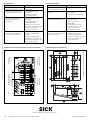
Maßbild/dimensioned drawing
Alle Angaben in mm (inch)/All dimensions in mm (inch)
Aufbau, Klemmenbelegung/design, terminal assignment
8010000/TF10/2009-08 · 5M/TR <PM 6.5> · KE · Printed in Germany · Subject to change without prior notice · The specified product features and technical data do not represent any guarantee · AftE6305sw
LEDs
Konfigurationsschalter
Configuration switches
Anschluss CLV41x
CLV41x connection
Klemmenleisten
Terminal strips
Anschluss PC
PC connection
8. Fehlersuche
Störung
• Versorgungsspg. angeschlossen,
aber LED „Power“ leuchtet nicht
• Datenübertragung auf der Host-
schnittstelle funktioniert nicht
• Signale des angeschlossenen
Lesetaktsensors bleiben
wirkungslos
• Nach Anschluss des PCs an den
Stecker „AUX“ kein Zugriff auf
den CLV41x mit CLV-Setup
Abhilfe
• Schalter S 1 (Power) in Position
„ON“ bringen
• Host gemäß CLV-Connect
anschließen
• Schalter S 5 in Position
„HOSTÅ410“ bringen
• Sensor gemäß CLV-Connect
anschließen
• Stellung des Schalters S 3
(SGND–GND) prüfen
• Mit Hilfe von „CLV-Setup“ die
Quelle des Lesetaktes im CLV41x
auf „Sensor 1“ einstellen.
Download zum CLV41x!
• Schalter S 5 für Zugriff temporär
in Position „RS232ÆAUX“
bringen
• Mit Hilfe der Funktion „Auto-
BaudDetect“ in „CLV-Setup“ die
Kommunikationsparameter des
PC automatisch wählen
8. Troubleshoooting
Malfunction
• “Power” LED does not light up
when power supply is connected
• Data transfer malfunction on host
interface
• Signals from connected reading
clock sensor have no effect
• Cannot access CLV41x with CLV-
Setup after connecting the PC to
the “AUX” connector
Remedy
• Set switch S 1 (Power) to “ON”
• Connect host in accordance with
CLV-Connect
• Set switch S 5 to “HOSTÅ410”
• Connect sensor in accordance
with CLV-Connect
• Check the S 3 switch
(SGND–GND)
• Using “CLV-Setup”, set the
reading clock source on the
CLV 41x to “Sensor 1”.
Download to the CLV41x
• Set switch S 5 temporarily to
“RS232ÆAUX” for access
• Using the “AutoBaudDetect”
function in “CLV-Setup”, configure
the PC communication para-
meters automatically
SICK AG · Waldkirch · Germany · www.sick.com
-
 1
1
-
 2
2
-
 3
3
-
 4
4


in anderen Sprachen
- English: SICK CDB410 Operating instructions
Verwandte Papiere
-
SICK CDB405 Bedienungsanleitung
-
-
-
-
-
-
-
-
-