SICK CMP400 Power Supply Module for CDM410/420 Connection Module Mounting instructions
- Typ
- Mounting instructions

© SICK AG · Division Auto Ident · Germany · All rights reserved 1 # 28010365/S011/2008-01
CMP400
1. Produkteigenschaften
■ Power-Supply-Modul zum Einbau in ein SICK Anschlussmodul
aus der Serie CDM410 oder CDM420
■ Spannungsversorgung eines SICK Barcodescanners CLV41x,
CLV 42x ... 45x, CLV6xx oder Image Code Readers ICR84x/85x
direkt aus einem Wechselstromnetz
■ Eingangsspannung AC 100 ... 250 V, 50 ... 60 Hz, Ausgangs-
spannung DC 24 V, max. 10,8 W (kurzschlussfest)
■ Federkraftklemmen für Anschluss des Wechselstromnetzes,
Flachbandleitung mit Stecker für Anschluss an CDM410/420
■ Nicht geeignet für Barcodescanner mit Heizung
■ Wartungsfrei
■ Das CMP400 ist ausschließlich für den Einsatz in Industrieum-
gebungen bestimmt. Beim Einsatz im Wohnbereich können
Funkstörungen entstehen.
■ Reparatur des Moduls im Schadensfall nur durch SICK
Weitere Produktinformationen:
¾ Siehe www.sick.com
EG-Konformitätserklärung:
¾ Auf Anforderung
2. Voraussetzungen zur Installation und Inbetriebnahme
■ Anschlussmodul CDM410/420 mit Betriebsanleitung
■ Versorgungsspannung AC 100 ... 250 V, 50 ... 60 Hz
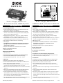
3. Montage
■ Einbauort im Anschlussmodul: siehe Skizze oben
■ Power-Supply-Modul einbauen vor Montage des CDM410/420
1. Deckel des Anschlussmoduls abnehmen.
2. Power-Supply-Modul CMP400 so in das Anschlussmodul einset-
zen, dass der 4-pol. Klemmenblock nach vorne weist.
3. Modul auf den beiden Abstandsnasen vorne und hinten im Boden
aufsetzen.
4. Stecker der Flachbandleitung auf die gegenüberliegende Feder-
leiste der Basiskarte aufsetzen und vorsichtig andrücken.
5. Power-Supply-Modul befestigen. Hierzu die zwei beigelegten
Abstandshülsen mit den vertieften Seiten so auf die Abstands-
nasen aufsetzen, dass die Hülsen die Nasen abdecken. Schrau-
ben in die Hülsen einführen und festdrehen.
6. Nach Beendigung der elektrischen Anschlussarbeiten und Testen
der Installation Deckel wieder aufsetzen und befestigen.
Power-Supply-Modul für
Anschlussmodul CDM410/420
Power Supply Module for
CDM410/420 Connection Module
1. Features
■ Power supply module for installation in a SICK connection module
in the CDM410 or CDM420 series
■ Power supply for one SICK bar code scanner CLV41x, CLV42x to
45x, CLV6xx or image code reader ICR 84x/85x directly from an
AC power line. Not suitable for devices with heater
■ Input voltage 100 to 250 V AC, 50 to 60 Hz, output voltage
24 V DC, max. 10.8 W (short-circuit proof)
■ Spring terminals for AC power line, ribbon cable with connector to
connect the CMP400 to the main board of the CDM410/420
■ Maintenance free
■ The CMP400 ist exclusively intended for use in an industrial
environment. In case of use in residential areas, RF
interferences may occur.
■ Damaged modules must be repaired by SICK only
Further Product Info:
¾ See www.sick.com
EC Certificate of Conformity:
¾ On request
2. Installation and Commissioning Requirements
■ CDM410/420 Connection Module with operating instructions
■ 100 to 250 V AC, 50 to 60 Hz power line
3. Installation
■ Installation location in the CDM410/420: see diagram above
■ Install the power supply module before mounting the CDM
1. Remove the cover of the connection module.
2. Fit the CMP400 power supply module into the connection
module in such a way that the 4-pole terminal block is facing
forwards.
3. Place the module on the two spacer lugs at the front and back on
the base.
4. Insert the ribbon cable plug into the socket connector and
carefully press in.
5. Secure the power supply module. To do so, place the two spacer
sleeves with grooved sides onto the spacer lugs in such a way
that the sleeves cover the lugs. Insert screws into the sleeves and
screw tight.
6. Once you have finished the electrical connection and tested the
installation, replace and secure the cover.
MontagMontag
MontagMontag
Montag
eanleitungeanleitung
eanleitungeanleitung
eanleitung
FF
FF
F
itting Insitting Ins
itting Insitting Ins
itting Ins
trtr
trtr
tr
uctionsuctions
uctionsuctions
uctions
Power-Supply-
Modul CMP400
CMP400 Power
Supply Module
CDM410/420

2 # 2 © SICK AG · Division Auto Ident · Germany · All rights reserved 8010365/S011/2008-01
Hinweis:
Bei Verwendung des CMP400 verliert das Anschlussmodul und der
angeschlossene Barcodescanner die UL-Zertifizierung.
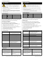
Verdrahtung des CMP400:
■ Im CDM410/420 ist PE mit Shield verbunden
■ Frontblende (Metall) des CDM an Shield anschließen
■ Alle Aderquerschnitte und deren korrekte Absicherung gemäß
gültiger Normen wählen und ausführen
1. Im CDM410/420 Schalter S 1 (Power) auf „OFF“ stellen.
2. Wechselstromnetz über Stecker oder Schalter spannungsfrei an
das Power-Supply-Modul CMP400 anschließen.
3. Versorgungsspannung einschalten.
4. Schalter S 1 (Power) auf „ON“ stellen.
Note:
Using the CMP400, the UL certification for the connection module
and the connected bar code scanner is not longer valid.
CMP400 wiring:
■ In the CDM410/420, the PE is connected with a shield.
■ Connect the front aperture (metal) on the CDM to the shield.
■ All wire cross-sections have to be selected and implemented
according to valid engineering standards
1. In the CDM410/420 set switch S 1 (Power) to “OFF“.
2. Connect the AC power line to the CMP400 module using a switch
connector (only when the power supply is switched off).
3. Switch on the AC supply voltage.
4. Set switch S 1 (Power) to “ON“.
4. Elektrische Installation
4. Electrical Installation
Klemmenbelegung:
SICK AG · Waldkirch · Germany · www.sick.com · 8010365/S011/2008-01 · 5M/TR <PM 6.5> · KE · Printed in Germany · Subject to change without prior notice · The specified product features and technical data do not represent any guarantee · AftE6005sw
5. Technische Daten
Typ CMP400 (Nr. 2029468)
Elektrische Anschlüsse 4-pol. Federkraftklemmen (für Adern 0,14 ...
1,5 mm
2
), Flachbandleitung mit Stecker
Versorgungsspannung AC 100 ... 250 V, 50 ... 60 Hz
Ausgangsspannung DC 24 V; max. 10,8 W; kurzschlussfest
Sicherung Primär- und sekundärseitig
Gehäuse/Prüfzeichen Kunststoff/CE
Elektrische Sicherheit nach EN 61010-1 (2001-03)
Schutzklasse I, nach EN 61140 (2002-03)
Überspannungskategorie 2, nach IEC 664-1 (1992)
EMV-Prüfung EN 61000-6-2 (2001-10); EN 61000-6-4
(2001-10); EN 55011 (1998-05),
A1 (1998-08), A2 (2002-10)
Abmessungen 94 mm x 52 mm x 22 mm
Gewicht ca. 100 g
Temperatur (Betrieb/Lager) 0 ... +40°C/ –20 ... +70°C
Rel. Luftfeuchtigkeit max. 90 %, nicht kondensierend
Klemme Signal Verbindung an
PE Schutzerde
L Phase AC 100 ... 250 V/ 50 ... 60 Hz
N Nullleiter 0 V
5. Technical Data
Type CMP400 (No. 2029468)
Electrical connections 4-pin spring terminals, for cores 0.14 to
1.5 mm
2
(approx. 26 to 16 AWG),
ribbon cable with connector
AC power line in 100 to 250 V AC, 50 to 60 Hz
Output voltage 24 V DC, max. 10.8 W, short-circuit proof
Fuse Primary and secondary side
Housing/Conformity Plastic/CE
Electrical safety to EN 61010-1 (2001-03)
Protection class I, to EN 61140 (2002-03)
Surge category 2, to IEC 664-1 (1992)
EMV-tested (accord. to) EN 61000-6-2 (2001-10); EN 61000-6-4
(2001-10); EN 55011 (1998-05),
A1 (1998-08), A2 (2002-10)
Dimensions (W x H x D) 94 mm x 52 mm x 22 mm (3.7 x 2 x 0.87 inch)
Weight Approx. 100 g (approx. 3.5 oz)
Temperature 0 to +40°C/ –20 to +70°C
(operation/storage) (+32 to +104°F/ –4 to +158°F)
Rel. air humidity Max. 90 %, non-condensing
6. Fehlersuche
Störung
• Bei Anlegen der Versorgungsspg.
leuchtet die LED „Power“ nicht
• Während des Betriebs erlischt die
LED „Power“ (Strombegrenzung
des CMP400 spricht an)
Abhilfe
• Schalter S 1 (Power) auf „ON“
stellen
• Schalter S 1 auf „OFF“ stellen
• Ursache beseitigen (Kurzschluss/
Überlastung)
• Schalter S 1 auf „ON“ stellen
Terminal assignment:
Terminal Signal Connection to
PE Protection earth (PE)
L Phase 100 to 250 V AC/ 50 to 60 Hz
N Zero conductor 0 V
6. Troubleshoooting
Malfunction
• “Power” LED does not light up
when power supply is connected
• During operation the “Power” LED
extinguishes (The CMP400
current limiter trips.)
Remedy
• Set switch S 1 (Power) to “ON”
• Set switch S 1 (Power) to “OFF”
• Rectify the problem (short-circuit/
overload).
• Set switch S 1 (Power) to “ON”
GEFAHR
Verletzungsgefahr durch elektrischen Strom!
Das Modul CMP400 wird an Wechselspannung
AC 100 ... 250 V, 50 ... 60 Hz angeschlossen.
¾ Anschluss nur durch ausreichend qualifiziertes Fachpersonal
durchführen lassen.
¾ Bei Arbeiten in elektrischen Anlagen die einschlägigen Sicher-
heitsvorschriften beachten.
¾ CMP400 nur eingebaut im geschlossenen Anschlussmodul in
Betrieb nehmen. Sonst ggf. Berührungsgefahr mit gefährlicher
Wechselspannung!
Shock hazard!
The CMP400 power supply module is connected to
a voltage of 100 to 250 V AC, 50 to 60 Hz.
¾ The module should only be connected by sufficiently qualified
personnel.
¾ Always observe the relevant safety instructions when working
with electrical equipment.
¾ For safety reasons, the CMP400 module must only be operated
when installed in the closed connection module!
DANGER
-
 1
1
-
 2
2


SICK CMP400 Power Supply Module for CDM410/420 Connection Module Mounting instructions
- Typ
- Mounting instructions
in anderen Sprachen
Verwandte Artikel
-
SICK CDM410-0001 Connection Module for CLV41x Bar Code Scanner Bedienungsanleitung
-
-
-
-
-
-
-
-
-