SICK CDB620 Connection Module Bedienungsanleitung
- Typ
- Bedienungsanleitung

1 # 88012119/YTW9/2016-03 © SICK AG · Germany · All rights reserved · Subject to change without notice · Irrtümer und Änderungen vorbehalten
CDB620
1. Bestimmungsgemäße Verwendung
■Basis-Anschlussmodul (im Folgenden CDB620 genannt) zum An-
schluss eines SICK-Identikationssensors (im Folgenden ID-Sen-
sor genannt) an Host (seriell), CAN-Sensor-Netzwerk sowie an
Peripherie und Stromversorgung. Der Anschluss des ID-Sensors
an das Ethernet (typabhängig) erfolgt nicht über das CDB620.
■Unterstützte ID-Sensoren
*)
: Barcodescanner CLV61x bis CLV65x,
kamerabasierte Codeleser Lector62x sowie RFID-Schreib-/Lese-
geräte RFH6xx (HF) und RFU62x (UHF)
2. Produkteigenschaften
■Basis zur Aufnahme eines optionalen CMC600 (Connection Mo-
dule Cloning) für externe Speicherung der Kongurationsparame-
ter des ID-Sensors. Dient auch der Aktivierung von Betriebsarten
und Erweiterung des ID-Sensors um jeweils zwei digitale Schalt-
ein- und -ausgänge (bei CLV61x bis CLV65x, Lector62x, RFH6xx
und RFU62x)
■9-pol. D-Sub-Stecker intern: Anschluss der Aux-Schnittstelle (seri-
ell RS-232) an PC zur Konguration und Diagnose des ID-Sensors
■Anschlussklemmen für serielle Host-Schnittstelle, CAN-Bus
(CDB620-101: 2x M12-Steckverbindungen), Schaltein- und -aus-
gänge, Stromversorgung, Abschirmung
■Durch Deckel sichtbar: LEDs zur Anzeige von aktiven Schaltein-
und -ausgängen sowie Schalterstellungen der Modulkonguration
■Schutzart IP 65 (nicht durch UL geprüft)
■Betriebsumgebungstemperatur–35 °C bis +40 °C
■Montierbar bei geschlossenem Deckel
■Wartungsfrei
■UL-zertiziert bei Verwendung eines folgenden Netzteils:
UL60950-1: LPS oder Class 2 (UL1310)
UL508: Class 2 (UL1310)
Weitere Produktinformationen und EU-Konformitätserklärung:
Siehe Produktseite im Internet unter www.sick.com/cdb
3. Voraussetzungen zur Installation und Inbetriebnahme
■Versorgungsspannung DC 24 V
■Montage-, Anschluss- und Kongurationsarbeiten nur bei Umge-
bungstemperaturen von 0 °C bis +40 °C vornehmen!
*) Auch geeignet für CLV42x bis CLV45x, CLV48x, CLV/CLX49x sowie ICR84x-2/85x-2.
Anschlussmodul
Betriebsanleitung Operating Instructions
Connection Module
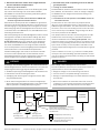
1. Intended use
■Basic module (referred to as CDB620 below) for connecting a
SICK identication sensor (referred to as ID sensor below) to the
host (serial), CAN sensor network, as well as to the peripheral
equipment and power supply. The CDB620 is not used to connect
the ID sensors to Ethernet (type-dependent).
■Supported ID sensors
*)
: Bar code scanners CLV61x to CLV65x,
image-based code reader Lector62x, as well as RFID write/read
devices RFH6xx (HF) and RFU62x (UHF)
2. Features
■Basis for optional CMC600 (Connection Module Cloning) integra-
tion for external storage of the ID sensor’s conguration param-
eters. Also for activation of operating modes as well as for exten-
sion of the ID sensor with each of two digital switching inputs and
outputs (on CLV61x to CLV65x, Lector62x, RFH6xx and RFU62x)
■9-pin internal D-Sub male connector: for connecting the AUX
interface (serial RS-232) to a PC for conguring and troubleshoot-
ing the ID sensor
■Terminals for serial host interface, CAN bus (CDB620-101: 2 x
M12 connections), switching inputs and outputs, power supply,
and shield
■Externally visible LEDs for displaying active switching inputs and
outputs, as well as switch settings for module conguration
■Enclosure rating IP 65 (not tested by UL)
■Operation ambient temperature range –35 °C to +40 °C
■Installation possible with closed cover
■Maintenance-free
■UL certicated when the following power supply unit is used:
UL60950-1: LPS or Class 2 (UL1310)
UL508: Class 2 (UL1310)
Further Product Information and EU Conformity Declaration:
See product page on the Internet at www.sick.com/cdb
3. Installation and Commissioning Requirements
■24 V DC power supply
■Perform mounting, electrical connection and conguration works
only at operation ambient temperature range 0 °C to +40 °C!
*) Also suitable for CLV42x to CLV45x, CLV48x, CLV/CLX49x as well as ICR84x-2/85x-2.
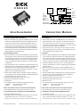
“Sensor 2”
“Host”
V
S
“Sensor 1”
“Result 1”
Licht-
schranke
(Lesetakt)
Photo reex
switch
(Reading clock)
Schalter/switch
Teach-in matchcode
“Aux”
PC
HOST
SPS/PLC
ID
Sensor
CDB620
. . . .
. . . . .
“CAN”
CAN bus
“Result 2”
SPS/PLC
CMC600
“Out 1”
“Out 2”
“In 1”
“In 2”

2 # 8 8012119/YTW9/2016-03© SICK AG · Germany · All rights reserved · Subject to change without notice · Irrtümer und Änderungen vorbehalten
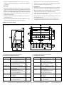
Maßbild/dimensioned drawing
Alle Angaben in mm (inch)/All dimensions in mm (inch)
5. Kongurationselemente und Anzeigen
5.1 Funktion der Kongurationsschalter
Schalter Funktion Default
S 1 (Power) Anliegende Versorgungsspannung: ON
ON: Versorgungsspannung U
IN
* ein
OFF: Versorgungsspannung U
IN
* aus
S 2 (TermCAN) Terminierung des CAN-Busses: OFF
ON: Widerstand 120 Ohm zugeschaltet
OFF: Keine Terminierung
S 3 (SGND-GND) Bezugspotenzial für Sensor-GND: OFF
ON: Verbunden mit GND des ID-Sensors
OFF: Potenzialfrei
S 4 (CMC) Integration des CMC600: NO
„YES“: CMC600 in Leitung der Aux-
Schnittstelle des ID-Sensors geschaltet
„NO“: kein CMC600 gesteckt
S 6 (RS) RS-422/485-Umschaltung OFF
ON: RS-485
OFF: RS-422
S 7 (Term485) RS-485-Terminierung (Empfänger) OFF
ON: Widerst. 120 Ohm zugeschaltet
OFF: Keine Terminierung
5. Conguration Elements and Displays
5.1 Conguration Switches
Switch Function Default
S 1 (Power) Power supply: ON
ON: Supply voltage U
IN
* on
OFF: Supply voltage U
IN
* off
S 2 (TermCAN) CAN bus termination: OFF
ON: 120 Ohm resistor connected
OFF: No termination
S 3 (SGND-GND) Reference potential for sensor GND: OFF
ON: Connected to ID sensor GND
OFF: Floating
S 4 (CMC) CMC600 integration: NO
“YES”: CMC600 connected to AUX
interface of the ID sensor
“NO”: CMC600 not connected
S 6 (RS) RS-422/485 selector OFF
ON: RS 485
OFF: RS 422
S 7 (Term485) RS-485 termination (receiver): OFF
ON: 120 Ohm resistor connected
OFF: No termination
■Einsatz bei Umgebungstemperaturen 0 °C bis –35 °C nur im
Zustand der Ruhe (keine Montage-, Anschluss- oder Kongurati-
onsarbeiten).
4. Montage
■Stets freier Zugang zum internen Stecker „AUX“ erforderlich für
Zugriff auf den ID-Sensor über RS-232 (Konguration/Diagnose)
■Maximale Leitungslänge zwischen CDB620 und ID-Sensor beim
Einsatz von Verlängerungsleitungen: 10 m (RS-232-Schnittstelle!)
■Abgenommener Deckel mit Anschlussbild um 180° gedreht in
Parkposition arretierbar
Bohrungs- und Gehäusemaße siehe Maßbild, max. Schrauben-
durchmesser 4 mm
Einbau und Inbetriebnahme des optionalen CMC600 siehe „Be-
triebsanleitung CMC600-101“ (Artikel-Nr. 8015190)
■Application of the module at operation ambient temperature
range 0 °C to –35 °C only in rest status (without any mounting,
electrical installation or conguration works).
4. Installation
■Permanent access to internal “AUX” male connector is required
for access to ID sensor via RS-232 (conguration/diagnostics)
■Max. cable length between CDB620 and ID sensor if extension
cables are used: 10 m because of RS-232 interface
■Cover with connection diagram can be removed, rotated through
180°, and locked in park position
See dimensioned drawing for hole and housing dimensions, max.
screw diameter 4 mm
For installing and commissioning the optional CMC600, see
“CMC600-101 operating instructions” (Part no. 8015190)
Abb. 1: Abmessungen des CDB620/Fig. 1: Dimensions of the CDB620

3 # 88012119/YTW9/2016-03 © SICK AG · Germany · All rights reserved · Subject to change without notice · Irrtümer und Änderungen vorbehalten
6. Electrical Installation
6.1 Data Interfaces
Recommended max. cable length from ID sensor to host
:
5.2 Funktion der LEDs
LED Farbe Funktion
Power Grün Leuchtet, wenn die Versorgungsspannung
(U
IN
*) am CDB620 anliegt und Schalter S 1 auf „ON“
Sensor 1, 2 Grün Leuchtet, wenn der entsprechende (zusätzliche)
In 1
*)
, 2
*)
Eingang des ID-Sensors (über CMC600) schaltet
Result 1, 2 Orange Leuchtet, wenn der entsprechende (zusätzliche)
Out 1
*)
, 2
*)
Ausgang des ID-Sensors (über CMC600) schaltet
*)
Voraussetzung ist das Modul CMC600.
6. Elektrische Installation
6.1 Datenschnittstellen
Empfohlene max. Leitungslänge vom ID-Sensor zum Host:
6.2 Versorgungsspannung U
IN
Die Höhe der erforderlichen Versorgungsspannung ist abhängig
vom anzuschließenden ID-Sensor:
5.2 LEDs
LED Color Function
Power Green Lights up when the power supply is connected
(U
IN
*) to the CDB620 and switch S 1 is set to “ON”
Sensor 1, 2 Green Lights up when the corresponding (additional)
In 1
*)
, 2
*)
ID sensor input switches (via CMC600)
Result 1, 2 Orange Lights up when the corresponding (additional)
Out 1
*)
, 2
*)
ID sensor output switches (via CMC600)
*)
A CMC600 module is required.
Interface type Data transfer rate Distance to host
RS-232 Up to 19.2 kBd Max. 10 m
38.4 kBd ... 57.6 kBd Max. 3 m
RS-422 Max. 38.4 kBd Max. 1,200 m
Max. 57.6 kBd Max. 500 m
Schnittstellentyp Datenübertragungsrate Entfernung z. Host
RS-232 Bis 19,2 kBd Max. 10 m
38,4 kBd ... 57,6 kBd Max. 3 m
RS-422 Max. 38,4 kBd Max. 1.200 m
Max. 57,6 kBd Max. 500 m
ID-Sensor Versorgungsspannung
CLV61x, CLV62x, Lector62x DC 10 V ... 30 V
CLV63x ... CLV65x ohne Heizung DC 18 V ... 30 V
CLV63x ... CLV65x mit Heizung DC 24 V ± 10 %
RFH6xx, RFU620-104xx DC 10 V ... 30 V
RFU620-101xx, bis –25 °C DC 10 V ... 30 V
RFU620-101xx, bei –25 °C ... –35 °C DC 20 V ... 30 V
CLV42x ... CLV45x, ICR85x-2 DC 10 V ... 30 V
ICR84x-2 DC 15 V ... 30 V
CLV480, CLV/CLX490 ohne Heizung DC 18 V ... 30 V
CLV480, CLV/CLX490 mit Heizung DC 24 V + 20 %/– 10 %
6.2 Supply voltage U
IN
(V
IN
)
The rate of the required supply voltage depends on ID sensor to be
connected:
ID sensor Supply voltage
CLV61x, CLV62x, Lector62x 10 V to 30 V DC
CLV63x ... CLV65x without heater 18 V to 30 V DC
CLV63x ... CLV65x with heater 24 V DC ± 10 %
RFH6xx, RFU620-104xx 10 V to 30 V DC
RFU620-101xx, down to –25 °C 10 V to 30 V DC
RFU620-101xx, from –25 °C to –35 °C 20 V to 30 V DC
CLV42x ... CLV45x , ICR85x-2 10 V to 30 V DC
ICR84x-2 15 V to 30 V DC
CLV480, CLV/CLX490 with heater 18 V to 30 V DC
CLV480, CLV/CLX490 without heater 24 V DC + 20 %/– 10 %
Verletzungsgefahr durch elektrischen Strom!
Wird die Versorgungsspannung durch ein Netzteil
erzeugt, kann mangelhafte elektrische Trennung
zwischen Eingangs- und Ausgangskreis des Netzteils
zu einem Stromschlag führen.
GEFAHR
Nur ein Netzteil verwenden, dessen Ausgangskreis gegenüber
dem Eingangskreis eine sichere elektrische Trennung besitzt.
Beispielsweise durch einen Sicherheitstrafo gemäß EN 61558-1.
6.4 Verdrahtung des CDB620
■Elektroinstallation nur durch ausgebildetes Fachpersonal durch-
führen.
■Bei Arbeiten in elektrischen Anlagen die gängigen Sicherheitsvor-
schriften beachten.
■Elektrische Verbindungen nur im spannungsfreien Zustand her-
stellen oder trennen.
■Um den Kurzschluss- und Überlastungschutz der abgehenden
Versorgungsleitungen (U
IN
*) zum ID-Sensor sicherzustellen,
müssen die verwendeten Aderquerschnitte unter Berücksichti-
gung der im CDB620 eingebauten Sicherung ausgelegt werden.
Hierbei folgende Normen beachten: DIN VDE 0100 (Teil 430),
Risk of injuries due to electrical current!
If the supply voltage is provided by a power supply
unit, insufcient electrical insulation between input
and output circuit of the unit can cause an electric
shock.
DANGER
Only use a power supply unit whose output circuit is safely electri-
cally isolated from the input circuit by means of a safety isolating
transformer according to EN 61558-1, for example.
6.4 Wiring the CDB620
■Electrical installation should only be carried out by qualied staff.
■Observe the current safety regulations when working on electrical
systems.
■Connect or disconnect current linkages only under de-energized
conditions.
■To ensure that the outgoing supply cables (U
IN
*) to the ID sensor
are protected against short-circuits and overload, the wire
cross-sections must be dimensioned in accordance with the fuse
installed in the CDB620. The valid national standards must be
observed.

4 # 8 8012119/YTW9/2016-03© SICK AG · Germany · All rights reserved · Subject to change without notice · Irrtümer und Änderungen vorbehalten
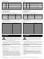
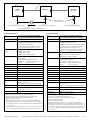
Aufbau, Klemmenbelegung/design, terminal assignment
LEDs
Kongurationsschalter
Conguration switches
Anschluss ID-Sensor
ID Sensor connection
Klemmleisten
Terminal strips
Anschluss PC
PC connection
Steckplatz für CMC600
Plug-in slot for CMC600
CAN
bus
“Host”
“Result 1”
“Sensor 1”
ID sensor
ID sensor
ID sensor
CDB620
CDB620
CDB620
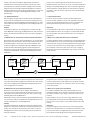
Schema: Aufbau eines CAN-Scanner-Netzwerkes
Diagram: Building a CAN scanner network
CDB620-101:
Pinbelegung M12-Steckverbindungen / pin assignment of M12 connectors
Pin Signal
1 Schirm/Shield
2 V
s
3 GND
4 CAN H
5 CAN L
Dose, M12,
5-polig, A-codiert.
Female connector,
M12, 5-pin, A-coded
CAN bus
Pin Signal
1 Schirm/Shield
2 V
s
3 GND
4 CAN H
5 CAN L
CAN bus
DIN VDE 0298 (Teil 4) bzw. DIN VDE 0891 (Teil 1)
■Klemmenbelegung siehe Anschlussbild unten oder im Deckel.
■Um Störeinüsse zu vermeiden, Leitungen möglichst nicht
parallel zu Stromversorgungs- und Motorleitungen verlegen
■Bezugspotenzial für die Schalteingänge mit Schalter S 3
(siehe Seite 2) wählen
1. Leitung des ID-Sensors an 15-pol. D-Sub-HD-Dose des
CDB620 anschließen. Für die M12-Anschlussvariante des
ID-Sensors folgende Adapterleitung verwenden:
– M12, 12-pol. auf D-Sub-HD, 15-pol., z. B. 2041834 (2 m)
– M12, 17-pol. auf D-Sub-HD, 15-pol., z. B. 2055419 (2 m)
2. Alle anderen Leitungen über Leitungsverschraubungen an
den Anschlussklemmen auegen.
3. Anwenderseitige Schirmung am CDB620 auegen (An-
schlussklemme „Shield“)
4. CAN-Bus: Falls CDB620 am Bussende, Terminierungswi-
der-stand mit Schalter S 2 (siehe Seite 2) zuschalten
Mit Kongurationssoftware SOPAS-ET
*)
den Treiber für die
verdrahtete serielle Host- und/oder CAN-Schnittstelle im
ID-Sensor aktivieren (siehe Betriebsanleitung des ID-Senors).
Hierzu PC mit 3-adr. RS-232-Datenleitung (Nullmodemlei-
tung) an Stecker „AUX“ im CDB620 anschließen oder ID-Sen-
sor über Ethernet kontaktieren (abhängig vom Sensortyp).
■For terminal assignment, see connection diagram below or inside
the cover.
■To prevent interference, do not lay cables parallel to power supply
or motor cables
■Choose reference potential for switching inputs with switch S 3 (see
page 2)
1. Connect the ID sensor cable to the 15-pin D-Sub HD female con-
nector of CDB620. For M12 connector version of the ID sensor use
the following adapter cable:
– M12, 12-pin to D-Sub-HD, 15-pin, e.g. 2041834 (2 m)
– M12, 17-pin to D-Sub-HD, 15-pin, e.g. 2055419 (2 m)
2. Connect all other cables to the terminals provided using cable
glands.
3. Connect the shield of your system to the CDB620 (“Shield” termi-
nal).
4. CAN bus: if CDB620 is integrated at bus end, connect termination
resistor with switch S 2 (see page 2)
Using SOPAS-ET
*)
conguration software, activate the driver for the
connected serial host and/or CAN interface in the ID sensor (see
the operating instructions of the ID sensor).
To do so, connect the PC to the “AUX” male connector on the
CDB620 using a 3-core RS 232 data cable (null modem cable) or
establish communication to the ID sensor via Ethernet (depends
on sensor type).
Abb. 2: Belegung der Anschlussklemmen und Schalter/Fig. 2: Functional attribution of terminals and switches
Stecker, M12,
5-polig, A-codiert.
Male connector, M12,
5-pin, A-coded
U
IN
* = Versorgungspannung U
IN
nach
Schalter S1 und Sicherung 0,8 A.
U
IN
* = Power supply voltage U
IN
be-
hind switch S1 and fuse 0.8 A
1
43
5
2
1
43
5
2
*) CLV-Setup für CLV42x bis CLV45x, CLV48x, CLV/CLX49x sowie ICR84x-2/85x-2. *) CLV-Setup for CLV42x to CLV45x, CLV48x, CLV/CLX49x as well as ICR84x-2/85x-2.

5 # 88012119/YTW9/2016-03 © SICK AG · Germany · All rights reserved · Subject to change without notice · Irrtümer und Änderungen vorbehalten
7. Elektrische Sicherheit: Gefahr durch Ausgleichsströme
bei unterschiedlichen Erdpotenzialen
7.1 Änderung der Norm 60950-1
Die Norm 60950-1 (2006-04) wurde mit der Änderung A11 (2009-
03) erweitert. Die Änderung ist ab 01-12-2010 verbindlich.
Das CDB620 ist auf elektrische Sicherheit gemäß dieser geänder-
ten Norm ausgelegt und geprüft.
7.2 Voraussetzungen für den sicheren Betrieb des CDB620 und
des daran angeschlossenen SICK ID-Sensors
Die ID-Sensoren werden jeweils über ein CDB620 mit geschirmten
Leitungen an die Peripherie geräte (SPS, Host, Lesetakt-Sensor (en),
Stromversorgung etc.) angeschlossen. Der Lei tungsschirm z.B. der
Datenleitung liegt dabei am Metallgehäuse der ID-Sensoren sowie
an der Klemmleiste des CDB620 auf. Über das CDB620 bietet sich
die Erdung des ID-Sensors an.
Falls die Peripheriegeräte ebenfalls Metallgehäuse besitzen und der
Leitungs schirm ebenfalls an deren Gehäuse auiegt, wird davon
ausgegangen, dass alle beteiligten Geräte in der Installation das
gleiche Erdpotenzial haben. Dies erfolgt z.B. durch die Montage
der Geräte auf lei tende Metallächen, die fachgerechte Erdung
der Geräte und Metallächen in der Anlage und falls erforderlich,
einen niederimpedanten und stromtragfähigen Poten zialausgleich
zwischen Bereichen mit unterschiedlichen Erdpotenzialen.
Sind diese Bedingungen nicht erfüllt, z.B. bei Geräten innerhalb
eines weit verteilten Sys tems über mehrere Gebäude, können
Potenzialausgleichströme über die Leitungsschirme zwischen den
Geräten aufgrund unterschiedlicher Erdpotenziale ießen.
7. Electrical safety: Risk of equalizing currents at different
ground potentials
7.1 Change to standard 60950-1
Standard 60950-1 (2006-04) has been added to with the change
A11 (2009-03). As of December 1, 2010, the change is obligatory.
The CDB620 has been designed and checked according to the
changed standard.
7.2 Conditions for the safe operation of the CDB620 and the con-
nected SICK ID sensor
The ID sensors are each connected to the peripheral devices
(PLC, host, clock reading pulse sensor(s), power supply etc.) via a
CDB620 using shielded cables. The cable shield on the data cable
for instance, lies on the metal housing of the ID sensors as well as
on the terminal strip of the CDB620. The grounding of the ID sen-
sors can be performed via the CDB620.
If the peripheral devices also have metal housing and if the cable
shield also lies on their housing, it is assumed that all devices
involved in installation have the same ground potential. This is
achieved for instance by mounting the devices on conductive metal
surfaces, correctly grounding the devices and metal surfaces in the
system and if necessary via a low-impedance and stable current
carrying equipotential bonding between areas with different ground
potentials.
If these conditions are not met, e.g. on devices in a widely distrib-
uted system over several buildings, potential equalization currents
may, due to different ground potentials, ow along the cable shields
between the devices.
Verletzungs- oder Beschädigungsgefahr durch elektrischen Strom!
Potentialausgleichsströme zwischen den ID-Sensoren und/oder den
Peripheriegeräten können ggf. folgende Auswirkungen haben:
■Gefährliche Spannungen am Metallgehäuse z.B. der ID-Sensoren
■Fehlverhalten oder die Zerstörung der Geräte
■Schädigung oder Zerstörung des Leitungsschirms durch Erhit-
zung sowie Kabelbrände
Wo die örtlichen Gegebenheiten ein sicheres Erdungskonzept
(gleiches Potenzial in allen Erdungspunkten) nicht erfüllen, Maß-
nahmen gemäß dem nachfol genden Kapitel ergreifen.
GEFAHR
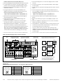
Abb. 3: Ströme in den Leitungsschirmen durch Erdpotentialunterschiede/Fig. 3: Currents in the cable shields due to differences in ground potential
DANGER
Risk of injury or risk of damage via electrical current!
Potential equalization currents between the ID sensors and/or the
peripheral devices can have the following effects:
■Dangerous voltages on the metal housing of the devices
■Incorrect function or irreparable damage to the devices
■Damage or irreparable damage of the cable shield due to heating
and cable res
Where local conditions are unfavorable and thus do not meet
conditions for a safe earthing method (same ground potential at
all grounding points), take measures from the next chapter.
ID-Sensor
geschlossene Stromschleife mit Ausgleichs-
strömen über Leitungsschirm.
closed current loop with equalizing currents
via cable shield
Erdungspunkt 2
grounding point 2
Erdungspunkt 1
grounding point 1
Erdpotenzialdifferenz/grounding potential difference
z.B. SPS
e.g. PLC
z.B. Sensor
e.g. sensor
I
U
CDB620
= Metallgehäuse/metal housing
= Kunststoffgehäuse/plastic housing
= geschirmte elektrische Leitung/
shielded electrical cable

6 # 8 8012119/YTW9/2016-03© SICK AG · Germany · All rights reserved · Subject to change without notice · Irrtümer und Änderungen vorbehalten
Zu Abb. 3. Durch unterschiedliche Erdpotentiale von Geräten
innerhalb eines verteilten Systems kö nnen hohe Ströme in den
Leitungsschirmen auftreten und diese schädigen oder zerstören.
Aufgrund des unzureichenden Erdpotenzialausgleichs entstehen
Spannungsdifferenzen zwischen den Erdungspunkten 1 und 2. Über
die geschirmten Leitungen und Metallgehäuse schließt sich die
Stromschleife.
7.3 Abhilfemaßnahmen
Die vorrangige Lösung für das Vermeiden von Potentialausgleichs-
strömen auf den Lei tungsschirmen ist die Sicherstellung eines nie-
derimpedanten und stromtragfähigen Poten tialausgleichs. Ist dieser
nicht realisierbar, dienen die folgenden beiden Lösungsansätze als
Vorschlag.
Wichtig!
Es wird davon abgeraten, die Lei tungsschirme aufzutrennen. Mit
dieser Maßnahme können ggf. die EMV-Grenzwerte und der sichere
Betrieb der Datenschnittstellen der Geräte nicht mehr eingehalten
werden.
a) Maßnahmen bei räumlich weit verteilten Systeminstallationen
Bei räumlich weit verteilten Systeminstallationen, mit entsprechend
großen Potenzialunter schieden, wird der Aufbau lokaler Inseln und
die Verbindung dieser Inseln über kommerziell erhältliche elekt-
ro-optische Signaltrenner empfohlen. Mit dieser Maßnahme wird
ein Höchstmaß an Robustheit gegenüber elektromagnetischen
Störun-gen erreicht, bei gleichzeitiger Ein haltung sämtlicher Anfor-
derungen der EN 60950-1. Fig. 4 zeigt die Wirkungsweise dieser
Maßnahme.
Abb. 4: Maßnahme: Einsatz elektro-optischer Signaltrenner/Fig. 4: Use of electro-optical signal converters
Durch den Einsatz der elektro-optischen Signaltrenner zwischen den
Inseln wird die Erdschleife aufgetrennt. Innerhalb der Inseln werden
durch einen tragfähigen Potenzialausgleich Ausgleichsströme auf
den Leitungsschirmen verhindert.
b) Maßnahmen bei kleinen Systeminstallationen
Bei kleineren Installationen mit nur geringen Potenzialunter-
schie-den kann die isolierte Montage des ID-Sensors und der Peri-
pheriegeräte eine hinreichende Lösung sein. Abb. 5, Seite 7 zeigt
die Wirkungsweise dieser Maßnahme.
Erdschleifen werden, selbst bei hohen Erdpotenzialdifferenzen wirk-
sam verhindert. Dadurch sind ießen keine Ausgleichsströme mehr
über die Leitungsschirme und Metallgehäuse.
Wichtig!
Die Stromversorgung für den ID-Sensor sowie die angeschlossene
Peripherie müssen dann ebenfalls die erforderliche Isolation sicher-
stellen. Unter Umständen kann zwischen den isoliert montierten
Metallgehäusen und dem örtli chen Erdpotenzial ein berührbares
Potenzial entstehen.
To g. 3. Due to different ground potentials of the devices in a
distributed system, high currents can occur in the cable shields and
damage or irreparably damage them. Due to insufcient ground po-
tential equalization, voltage differences arise between the ground-
ing points 1 and 2. The current loop closes via the shielded cables
and housing.
7.3 Remedial measures
The most common solution to prevent potential equalization
currents on cable shields is to ensure low-impedance and stable
current carrying equipotential bonding. If this is not possible the
following two solution approaches serve as a suggestion.
Important!
It is not advisable to open up the cable shields. As doing this means
that the EMC limit values can no longer be complied with and that
the safe operation of the device data interfaces can no longer be
guaranteed.
a) Measures for widely distributed system installations
On widely distributed system installations with correspondingly large
potential differences, we recommend setting up local islands and
connecting them using commercially available electro-optical signal
converters. This measure achieves a high degree of resistance to
electromagnetic interference while at the same time complying
with all the requirements of EN 60950-1. Fig. 4 shows the function
of this measure.
The ground loop is opened by using the electro-optical signal
converters between the islands. Within the local islands, a stable
equipotential bonding prevents equalizing currents from occurring
at the cable shields.
b) Measures for small system installations
For smaller installations with small potential differences, the
insulated installation of the ID sensor and peripheral devices can
be a sufcient solution. Fig. 5, Page 7 shows the function of this
measure.
Ground loops are, even in the event of large differences in the
ground potential, effectively prevented. Meaning that equalizing
currents cannot occur anymore via the cable shield and the metal
housing.
Important!
The power supply of the ID sensor and the connected peripheral
devices must also guarantee the required level of insulation. Under
certain circumstances, a tangible potential can develop between
the insulated metal housings and the local ground potential.
Erdungspunkt 1/grounding point 1
Elektro-
optischer
Trenner
Electro-optical
converter
Elektro-
optischer
Trenner
Electro-optical
converter
z.B. SPS
e.g. PLC
z.B. Sensor
e.g. sensor
Erdungspunkt 2/grounding point 2
ID-Sensor
geschirmte elektrische Leitung/shielded electricial cableMetallgehäuse/metal housing Lichtwellenleiter/fiber optic cable

7 # 88012119/YTW9/2016-03 © SICK AG · Germany · All rights reserved · Subject to change without notice · Irrtümer und Änderungen vorbehalten
8. Technische Daten
Typ CDB620-001 (Nr. 1042256), CDB620-101
(Nr. 1042257), CDB620-201 (Nr. 1042258)
Optische Anzeigen 9 x LED
Elektrische Anschlüsse Dose, D-Sub-HD, 15-pol./Stecker, D-Sub, 9-pol.
(CDB620-101: zusätzlich Stecker/Dose, M12,
5-pol., A-codiert für CAN-Bus)
Federkraftklemmen: 8 für Adern 0,14 mm
2
...
2,5 mm
2
/24 für Adern 0,14 mm
2
... 1 mm
2
Leitungsverschrau- (Klemmbereich ∅ 4,5 mm ... 10 (7) mm)
bungen CDB620-001: 4 x M16
CDB620-101: 2 x M16
CDB620-201: 4 x M16, 1 x M12
Versorgungsspannung DC 10 V... 30 V, SELV bzw. PELV nach
IEC 60364-4-41.
Verwendung eines folgenden Netzteils:
UL60950-1: LPS oder Class 2 (UL1310)
UL508: Class 2 (UL1310)
Leistungsaufnahme 1 W
Eingangsstrom Max. 2,4 A
1)
Sicherung
2)
Glasrohrsicherung 0,8 A träge
Gehäuse Polycarbonat
Prüfzeichen CE, UL
3)
Sicherheit Nach EN 60950-1: 2006/A11: 2009-03
Schutzklasse III, nach EN 61140
Schutzart IP 65
4)5)
, nach EN 60529
EMV-Prüfung Störaussendung: nach EN 61000-6-3: 2007-
01/ A1: 2011-03
Störfestigkeit: nach EN 61000-6-2: 2005-08
Gewicht Ca. 260 g
Umgebungstemperatur Betrieb: –35 °C ... +40 °C
6)
Lager: –35 °C ... +70 °C
Rel. Luftfeuchtigkeit Max. 90 %, nicht kondensierend
1) An Anschlussklemmen U
IN
.
2) Für Spannung U
IN
*, geschaltet über S 1 und interne Sicherung
3) Gültig bei entsprechender Gerätekennzeichnung auf dem Typenschild.
4) Bei Verwendung der SICK-Sensor-Standardanschlussleitung.
5) Schutzart nicht durch UL geprüft.
6) Betriebsumgebungstemperatur 0 °C bis –35 °C bei folgenden Bedingungen:
– Montage, elektrischer Anschluss sowie Konguration oder Power-up des Moduls
über eingebaute Schalter nur im normalen Betriebsumgebungtemperaturbereich
0 °C bis +40 °C.
– Einsatz bei Betriebsumgebungstemperatur 0 °C bis –35 °C nur im Zustand der
Ruhe (keine Montage-, Anschluss- oder Kongurationsarbeiten am Modul).
8. Technical Data
Type CDB620-001 (No. 1042256), CDB620-101
(No. 1042257), CDB620-201 (No. 1042258)
Visual indicators 9 x LEDs
Electrical connections 1 x female connector, D Sub HD, 15-pin
1 x male connector, D Sub, 9-pin
(CDB620-101: additional male connector/female
connector, M12, 5-pin, A-coded for CAN bus)
Spring terminals: 8 for cores 0.14 mm
2
...
2.5 mm
2
(approx. 26 to 13 AWG) and 24 for cores
0.14 mm
2
... 1 mm
2
(approx. 26 to 17 AWG)
Cable glands (for cables ∅ 4.5 mm ... 10 (7) mm)
CDB620-001/-101: 4 x M16/ 2 x M16
CDB620-201: 4 x M16, 1 x M12
Power supply 10 V to 30 V DC, SELV respectively PELV
according to IEC 60364-4-41.
Use the following power supply unit:
UL60950-1: LPS or Class 2 (UL1310)
UL508: Class 2 (UL1310)
Power consumption 1 W
Input current Max. 2.4 A
1)
Fuse
2)
Glass tube fuse 0.8 A, slow-blow
Housing Polycarbonate
Conformity CE, UL
3)
Safety Acc. to EN 60950-1: 2006/A11: 2009-03
Protection class III, according to EN 61140
Enclosure rating IP 65
4)5)
, according to EN 60529
EMC tested Emission: according to EN 61000-6-3: 2007-01/
A1: 2011-03
Immunity: according to EN 61000-6-2: 2005-08
Weight Approx. 260 g
Ambient Operation: –35 °C ... +40 °C
6)
temperature Storage: –35 °C ... +70 °C
Rel. air humidity Max. 90%, non-condensing
1) On terminals U
IN
.
2) For voltage U
IN
*, switched via S 1 and internal fuse.
3) Valid with corresponding product marking on the nameplate.
4) With SICK standard sensor cable.
5) Enclosure rating not tested by UL.
6) Operation ambient temperature 0 °C to –35 °C at the following conditions:
Installation, electrical connection as well as conguration or power-up of the mod-
ule using built-in switches only at normal operation ambient temperature range of
0 °C to +40 °C. Application of the module at operation ambient temperature only
in rest status (without any mounting, electrical installation or conguration works
on the module).
Abb. 5: Maßnahme: Isolierte Montage der Sensoren und der Peripheriegeräte/Fig. 5: Insulated assembly of the sensors and peripheral devices
Erdungspunkt/grounding point 2
Erdungspunkt
/grounding point 1
Isolierte Montage/
electrically insulated
U
z.B. SPS
e.g. PLC
Erdungspunkt/grounding point 3
z.B. Sensor
e.g. sensor
ID-Sensor
geschirmte elektrische Leitung/shielded electrical cable Metallgehäuse/metal housing
Erdpotenzialdifferenz/grounding potential difference

8 # 8 8012119/YTW9/2016-03© SICK AG · Germany · All rights reserved · Subject to change without notice · Irrtümer und Änderungen vorbehalten
8012119/YTW9/2016-03 · TM_8M · Printed in Germany
SICK AG · Waldkirch · Germany
For local sales ofces see www.sick.com
9. Fehlersuche
9. Troubleshoooting
*) CLV-Setup for CLV42x to CLV45x, CLV48x, CLV/CLX49x as well as ICR84x-2/85x-2.*) CLV-Setup für CLV42x bis CLV45x, CLV48x, CLV/CLX49x sowie ICR84x-2/85x-2.
Remedy
• Set switch S 1 (Power) to “ON”
• If no CMC600 is connected, set
switch S 4 to “NO”
• SOPAS-ET
*)
software: required de-
vice descrciption le for the related
ID sensor not existent or le related
to an other rmware version as the
current device uses.
Reload and insert the suitable
device descrciption le in SOPAS-
ET using the “Device manager”
function.
• SOPAS-ET
*)
: Using the “Device
search” function to start the com-
munication with the ID sensor
• Connect reading pulse sensor in
accordance with the operating
instructions of the ID sensor
• Check switch S 3 (SGND–GND)
• Using SOPAS-ET
*)
software, set
the reading pulse source on the ID
sensor to “Sensor 1”.
Perform a download to the ID
sensor.
Malfunction
• “Power” LED (U
IN
*) does not
light up when power supply U
IN
is connected
• Cannot access ID sensor with
SOPAS-ET
1)
conguration soft-
ware after connecting the PC to
the “AUX” male connector
• Signals from connected reading
pulse sensor have no effect to
the ID sensor
Störung
• Nach Anlegen der Versorgungs-
spannung U
IN
leuchtet die LED
„Power“ (U
IN
*) nicht
• Nach Anschluss des PCs an
den Stecker „AUX“ kein Zugriff
auf den ID-Sensor mit Kongu-
rationssoftware SOPAS-ET
1)
• Signale des angeschlossenen
Lesetakt-Sensors bleiben
wirkungslos im ID-Sensor
Abhilfe
• Schalter S 1 (Power) in Position
„ON“ bringen
• Wenn kein CMC600 gesteckt, Schal-
ter S 4 in Position „NO“ bringen
• SOPAS-ET
*)
: Erforderliche Gerätebe-
schreibungsdatei für betreffenden
ID-Sensor nicht vorhanden oder für
anderen Firmwarestand als vorlie-
gendes Gerät.
Passende Gerätebeschreibungs-
datei in SOPAS-ET über Funktion
„Gerätemanager“ nachladen und
einbinden.
• SOPAS-ET
*)
: Mit Funktion „Geräte-
suche“ die Kommunikation mit dem
ID-Sensor aufnehmen
• Lesetakt-Sensor gemäß Betriebsan-
leitung des ID-Sensors anschließen
• Stellung des Schalters S 3 prüfen
(SGND–GND)
• Mit SOPAS-ET
*)
die Quelle des
Lesetakts im ID-Sensor auf „Sensor
1“ einstellen.
Download zum ID-Sensor durch-
führen!
-
 1
1
-
 2
2
-
 3
3
-
 4
4
-
 5
5
-
 6
6
-
 7
7
-
 8
8


SICK CDB620 Connection Module Bedienungsanleitung
- Typ
- Bedienungsanleitung
in anderen Sprachen
Verwandte Artikel
-
SICK CDB650 Bedienungsanleitung
-
-
-
-
-
-
-
-
-