
1 # 88016155/XZ16/2013-12 © SICK AG · Germany · All rights reserved · Subject to change without notice · Irrtümer und Änderungen vorbehalten
CDB650-204
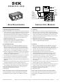
1. Bestimmungsgemäße Verwendung
■ Basis-Anschlussmodul zum Anschluss eines SICK-Identifikations-
sensors (ID-Sensor) an Host, CAN-Sensor-Netzwerk, Peripheriege-
räte und Stromversorgung. Der ID-Sensor ist hierzu mit einer
SICK-Standardleitung an der außen zugänglichen M12-Dose des
Anschlussmoduls anzuschließen. Über Kabelverschraubungen
und Klemmen werden die Stromversorgung zugeführt und
Signale auf Leitungen verteilt.
■ Unterstützte ID-Sensoren aus den Produktfamilien:
Barcodescanner CLV69x, kamerabasierte Codeleser
LECTOR
65x und RFID-Interrogatoren RFU63x
2. Produkteigenschaften
■ Basis zur Aufnahme eines optionalen CMC600 (Connection
Module Cloning) für externe Speicherung der Konfigurations-
parameter des ID-Sensors. Dient auch der Aktivierung von Be-
triebsarten sowie der Erweiterung des ID-Sensors um jeweils 2
digitale Schaltein- und -ausgänge (abhängig vom Sensortyp).
■ Integrierte Triggereinheit (Lastschalter) für den kamerabasierten
Codeleser LECTOR
65x zur Aktivierung einer externen Beleuch-
tung die keinen Triggereingang bietet
■ 17-polige M12-Dose zum Anschluss des ID-Sensors, bei Ausliefe-
rung mit Stopfen zu Erhaltung der Schutzart IP 65 versehen
■ 9-pol. D-Sub-Stecker intern, für Anschluss der seriellen Aux-
Schnittstelle (RS-232) des ID-Sensors an PC (Konfiguration oder
Diagnose)
■ Klemmen für serielle Host-Schnittstelle, CAN-Bus, Schaltein- und
-ausgänge, Triggereinheit, Stromversorgung, Schirmung
■ Durch Deckel sichtbar: LEDs zur Anzeige von aktiven Schaltein-
und -ausgängen sowie Stellungen der Konfigurationsschalter
■ Betriebsumgebungstemperaturbereich –40 °C bis +50 °C
■ Montierbar bei geschlossenem Deckel
■ Wartungsfrei
Weitere Produktinformationen und EG-Konformitätserklärung:
Siehe Produktseite im Internet (www.mysick.com/de/cdb)
Das CDB650-204 wird im Folgenden als „CDB650“ bezeichnet.
Anschlussmodul
Betriebsanleitung Operating Instructions
Connection Module
1. Inded Use
■ Basic module for connecting one SICK identification sensor
(ID sensor) to host, CAN sensor network, peripheral equipment,
and power supply. Connect the ID sensor using a SICK standard
cable to the externally accessible M12 female connector. Via
cable glands and terminals the power supply is connected and
signals are distributed to cables.
■ Supported ID sensors from the following product families:
CLV69x bar code scanners, LECTOR
65x image-based code
readers, and RFID Interrogators RFU63x
2. Features
■ Basis for optional CMC600 (Connection Module Cloning) inte-
gration for external storage of the ID sensor’s configuration
parameters. Also for activation of operating modes as well as for
extension of the ID sensor with each of two digital switching
inputs and outputs (depends on sensor type).
■ Integrated trigger unit (load interrupter switch) for the
LECTOR
65x image-based Code Reader to switch on/off an
external illumination which has not separate trigger input
■ 17-pin M12 female connector, for connecting the ID sensor,
equipped with a protective plug in delivery condition
■ 9-pin internal D-Sub male connector, for connecting the serial
Aux interface (RS 232) to a PC for configuring or troubleshooting
the ID sensor
■ Terminals for serial host interface, CAN bus, switching inputs and
outputs, trigger unit, power supply, and shield
■ Externally visible LEDs for displaying active switching inputs and
outputs, as well as switch settings for module configuration
■ Operation ambient temperature range –40 °C to +50 °C
■ Installation possible with closed cover
■ Maintenance-free
Further Product Information and EC Conformity Declaration:
See product page on the Internet (www.mysick.com/en/cdb)
In the following, the CDB650-204 is referred to simply as the
“CDB650”.
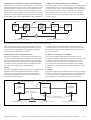
“SENS/IN2”
“Host”
DC 10 V ... 30 V
“SENS/IN 1”
“RES/OUT 1”
Licht-
schranke
(Lesetakt)
Photo reflex
switch
(Reading clock)
Schalter/switch
Teach-in matchcode
“Aux”
PC
HOST
SPS/PLC
ID
Sensor
CDB650
. . . .
. . . . .
“CAN”
CAN bus
“RES/OUT 2”
SPS/PLC
CMC600
“EXT. OUT 1”
“EXT. OUT 2”
“EXT. IN 1”
“EXT. IN 2”
“RES/OUT 3”
“RES/OUT 4”
SPS/PLC
SPS/PLC

2 # 8 8016155/XZ16/2013-12© SICK AG · Germany · All rights reserved · Subject to change without notice · Irrtümer und Änderungen vorbehalten
113.1
84.8
5.2
20.5 7.8
53.9
100
8.3 10.3
105.7
124.2
22.45
24.86
4.5
1
58.7
19.25 16.5 16.5 16.5 16.5 17.5
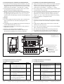
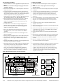
Alle Angaben in mm
All dimensions in mm
5. Konfigurationselemente und Anzeigen
5.1 Funktion der Konfigurationsschalter
5. Configuration Elements and Displays
5.1 Configuration Switches
3. Voraussetzungen zur Installation und Inbetriebnahme
■ PC/LapTop mit Internet-Zugang um Anschlusspläne in der jewei-
ligen Technischen Information des ID-Sensors herunterzuladen,
zugänglich als PDF auf der Produktseite des ID-Sensors im Web
(www.mysick.com/de/CLV69x, .../lector65x oder .../rfu63x).
■ Versorgungsspannung: siehe Technische Daten, Seite 8 sowie
Typenschild des anzuschließenden ID-Sensors
■ Montage-, Anschluss- und Konfigurationsarbeiten nur im Um-
gebungstemperaturbereich 0°C bis +50 °C vornehmen! Einsatz
im Umgebungstemperaturbereich 0°C bis –40 °C nur im Zu-
stand der Ruhe (keine Montage-, Anschluss- oder Konfigurations-
arbeiten).
4. Montage
■ Stets freier Zugang zum internen Stecker „AUX“ erforderlich für
Zugriff auf den ID-Sensor über RS-232 (Konfiguration oder
Diagnose)
■ Leitungslänge zwischen CDB650 und ID-Sensor bei Nutzung der
seriellen Datenschnittstellen: max. 10 m
■ Abgenommener Deckel mit Anschlussbild um 180° gedreht in
Parkposition arretierbar
Bohrungs- und Gehäusemaße siehe Maßbild.
Einbau und Inbetriebnahme des optionalen CMC600 siehe
„Betriebsanleitung CMC600-101“ (Artikel-Nr. 8015190)
Abb. 1: Abmessungen des CDB650/Fig. 1: Dimensions of the CDB650
3. Installation and Commissioning Requirements
■ Using a PC/LapTop with Internet access to load down connection
diagrams in the relating Technical Information (PDF) of the ID
sensor from the ID sensor’s product page on the Web
(www.mysick.com/en/CLV69x, .../lector65x or .../rfu63x).
■ Power supply voltage: see Technical Data, page 8 and nameplate
of the ID sensor to be connected.
■ Perform mounting, electrical connection and configuration works
only at operation ambient temperature range 0° C to +50 °C!
Application of the module at operation ambient temperature
range 0° C to –40 °C only in rest status (without any mounting,
electrical installation or configuration works).
4. Installation
■ Permanent access to internal “AUX” male connector is required
for access to the ID sensor via RS 232 (configuration or diagnos-
tics)
■ Length between CDB650 and ID sensor when the serial data
interfaces are used: max. 10 m
■ Cover with connection diagram can be removed, rotated through
180°, and locked in park position
See dimensioned drawing for hole and housing dimensions.
For installing and commissioning the optional CMC600, see
“CMC600-101 Operating Instructions” (part no. 8015190).
Max. Schraubendurchmesser 4 mm
Maximum screw diameter 4 mm
Kabelverschraubung, 5 x
Cable gland, 5 x
17-pol. M12-Dose, A-codiert
17-pin M12 female
connector, A-coded
Schalter Funktion Default
S 1 (Power) Anliegende Versorgungsspannung: ON
ON: Versorgungsspannung U
IN
* ein
OFF: Versorgungsspannung U
IN
* aus
S 2 (Term CAN) Terminierung des CAN-Busses: OFF
ON: Widerstand 120 Ohm zugeschaltet
OFF: keine Terminierung
S 3 (SGND-GND) Bezugspotenzial für Sensor-GND: OFF
ON: verbunden mit GND des ID-Sensors
OFF: potentialfrei
S 4 (CMC) Integration des CMC600: NO
„YES“: CMC600 in Leitung der Aux-
Schnittstelle des ID-Sensors geschaltet
„NO“: kein CMC600 gesteckt
Switch Function Default
S 1 (Power) Power supply: ON
ON: Supply voltage U
IN
* on
OFF: Supply voltage U
IN
* off
S 2 (Term CAN) CAN bus termination: OFF
ON: 120 Ohm resistor connected
OFF: No termination
S 3 (SGND-GND) Reference potential for sensor GND: OFF
ON: Connected to ID sensor GND
OFF: Floating
S 4 (CMC) CMC600 integration: NO
“YES”: CMC600 connected to Aux
interface of the ID sensor
“NO”: CMC600 not connected

3 # 88016155/XZ16/2013-12 © SICK AG · Germany · All rights reserved · Subject to change without notice · Irrtümer und Änderungen vorbehalten
6. Electrical Installation
6.1 Data Interfaces
Recommended max. cable length from ID sensor to host
:
5.2 Funktion der LEDs
LED Farbe Funktion
Power Grün Leuchtet, wenn die Versorgungsspannung
(U
IN
*) am CDB650 anliegt und Schalter S 1 auf „ON“
SENS/IN 1 Grün Leuchtet, wenn der entsprechende Eingang des
SENS/IN 2 ID-Sensors schaltet
EXT. IN 1
1)
Grün Leuchtet, wenn der entsprechende, zusätzliche
EXT. IN 2
1)
Eingang des ID-Sensors (über CMC600) schaltet
RES/OUT 1 Orange Leuchtet, wenn der entsprechende Ausgang des
... ID-Sensors vorhanden ist und schaltet
RES/OUT 4
EXT. OUT 1
1)
Orange Leuchtet, wenn der entsprechende, zusätzliche
EXT. OUT 2
1)
Ausgang des ID-Sensors (über CMC600) schaltet
1) Voraussetzung ist das Modul CMC600.
6. Elektrische Installation
6.1 Datenschnittstellen
Empfohlene max. Leitungslänge vom ID-Sensor zum Host:
6.3 Versorgungsspannung U
IN
Die Höhe der erforderlichen Versorgungsspannung ist abhängig
vom anzuschließenden ID-Sensor.
5.2 LEDs
Interface type Data transfer rate Distance to host
RS 232 Up to 19.2 kBd Max. 10 m
38.4 kBd ... 57.6 kBd Max. 3 m
RS 422 Max. 38.4 kBd Max. 1,200 m
Max. 57.6 kBd Max. 500 m
Schnittstellentyp Datenübertragungsrate Entfernung z. Host
RS-232 Bis 19,2 kBd Max. 10 m
38,4 kBd ... 57,6 kBd Max. 3 m
RS-422 Max. 38,4 kBd Max. 1.200 m
Max. 57,6 kBd Max. 500 m
6.2 Zusätzliche Schaltein- und Ausgänge
Die Zusatzfunktion des CMC600 unterstützt folgende ID-Sensoren:
ID-Sensor Zusätzl. Eingänge Zusätzl. Ausgänge
CLV69x/RFU63x/LECTOR
65x 2 2
6.3 Supply voltage U
IN
The required power supply voltage depends on the ID-sensor to be
connected.
6.2 Additional switching inputs and outputs
The CMC600 supports the following ID sensors:
ID sensor Additional inputs Additional outputs
CLV69x/RFU63x/LECTOR
65x 2 2
6.4 Sicherer Betrieb des CDB650 in einer Anlage
Das CDB650 ist auf Sicherheit gemäß EN 60950-1: 2006-04/
A11: 2009-03/A1: 2010-03 ausgelegt und geprüft.
Für die Verbindung zwischen CDB650 und ID-Sensor sowie für die
Datenübertragung (RS-232, RS-422/485, CAN) sind geschirmte
Leitungen zu verwenden. Der Leitungsschirm z. B. der Datenleitung
liegt dabei am Metallgehäuse der Sensoren sowie an der Klemmen-
leiste des CDB650 auf. Über das CDB650 bietet sich die Erdung
des SICK Sensors an.
Falls die Peripheriegeräte ebenfalls Metallgehäuse besitzen und der
Leitungsschirm ebenfalls an deren Gehäuse aufliegt, wird davon
ausgegangen, dass alle beteiligten Geräte in der Installation das
6.4 Conditions for the safe operation of the CDB650 in a system
The CDB650 is designed and tested for safety according to
EN 60950-1: 2006-04/A11: 2009-03/A1: 2010-03.
For the connections between CDB650 and ID sensor as well as for
the data transfer (RS-232, RS-422/485, CAN) shielded cables must
be used. The cable shield on the data cable for instance, lies on the
metal housing of the sensors and on the terminal strip of the
CDB650. The grounding of the SICK sensors can be performed via
the CDB650.
If the peripheral devices also have metal housing and if the cable
shield also lies on their housing, it is assumed that all devices
involved in installation have the same ground potential. This is
LED Color Function
Power Green Lights up when the power supply is connected
(U
IN
*) to the CDB650 and switch S 1 is set to “ON”
SENS/IN 1 Green Lights up when the corresponding ID sensor input
SENS/IN 2 switches
EXT. IN 1
1)
Green Lights up when the corresponding (additional)
EXT. IN 2
1)
ID sensor input switches (via CMC600)
RES/OUT 1 Orange Lights up when the corresponding ID sensor
... output exists and switches
RES/OUT 4
EXT. OUT 1
1)
Orange Lights up when the corresponding (additional)
EXT. OUT 2
1)
ID sensor output switches (via CMC600)
1) A CMC600 module is required.
Schalter Funktion Default
S 6 (RS 422/485) RS-422/485-Umschaltung: OFF
ON: RS-485
OFF: RS-422
S 7 (Term 485) RS-422-Terminierung (Empfänger): OFF
ON: Widerstand 120 Ohm zugeschaltet
OFF: keine Terminierung
(Fortsetzung)
Switch Function Default
S 6 (RS 422/485) RS 422/485 selector: OFF
ON: RS 485
OFF: RS 422
S 7 (Term 485) RS 422 termination (receiver): OFF
ON: 120 Ohm resistor connected
OFF: No termination
(continued)
ID-Sensor Versorgungsspannung
CLV69x DC 18 V ... 30 V
LECTOR
65x DC 24 V ± 20 %
RFU63x DC 18 V ... 30 V
Siehe hierzu auch Angaben auf dem Typenschild des ID-Sensors. See also details on the nameplate of the ID sensor.
ID sensor Supply voltage
CLV69x DC 18 V ... 30 V
LECTOR
65x DC 24 V ± 20 %
RFU63x DC 18 V ... 30 V

4 # 8 8016155/XZ16/2013-12© SICK AG · Germany · All rights reserved · Subject to change without notice · Irrtümer und Änderungen vorbehalten
gleiche Erdpotential haben. Dies erfolgt z. B. durch die Montage der
Geräte auf leitende Metallflächen, die fachgerechte Erdung der
Geräte/Metallflächen in der Anlage und falls erforderlich, einen
niederimpedanten und stromtragfähigen Potenzialausgleich
zwischen Bereichen mit unterschiedlichen Erdpotenzialen.
Sind diese Bedingungen nicht erfüllt, z. B. bei Geräten innerhalb
eines weit verteilten Systems über mehrere Gebäude, können
Potenzialausgleichsströme über die Leitungsschirme zwischen den
Geräten aufgrund unterschiedlicher Erdpotenziale fließen und zu
Gefahren führen.
achieved for instance by mounting the devices on conductive metal
surfaces, correctly grounding the devices/metal surfaces in the
system and if necessary via a low-impedance and stable current
carrying equipotential bonding between areas with different ground
potentials.
If these conditions are not met, e.g. on devices in a widely distrib-
uted system over several buildings, potential equalization currents
may, due to different ground potentials, flow along the cable shields
between the devices.
Verletzungs-/Beschädigungsgefahr durch elektrischen Strom!
Potentialausgleichsströme zwischen den Sensoren und/oder den
Peripheriegeräten können ggf. folgende Auswirkungen haben:
■ Gefährliche Spannungen am Metallgehäuse z. B. der Sensoren
■ Fehlverhalten oder die Zerstörung der Geräte
■ Schädigung/Zerstörung des Leitungsschirms durch Erhitzung
sowie Kabelbrände
Wo die örtlichen Gegebenheiten ein sicheres Erdungskonzept
(gleiches Potenzial in allen Erdungspunkten) nicht erfüllen,
Maßnahmen gemäß dem nachfolgenden Kapitel ergreifen.
GEFAHR
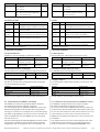
Abb. 2: Ströme in den Leitungsschirmen durch Erdpotenzialunterschiede/Fig. 2: Currents in the cable shields due to differences in ground potential
DANGER
Risk of injury/risk of damage via electrical current!
Potential equalization currents between the sensors and/or the
peripheral devices can have the following effects:
■ Dangerous voltages on the metal housing of the devices
■ Incorrect function or irreparable damage to the devices
■ Damage/irreparable damage of the cable shield due to heating
and cable fires
Where local conditions are unfavorable and thus do not meet
conditions for a safe earthing method (same ground potential at
all grounding points), take measures from the following chapter.
ID sensor
Geschlossene Stromschleife mit Ausgleichs-
strömen über Leitungsschirm.
Closed current loop with equalizing currents
via cable shield
Erdungspunkt 2
grounding point 2
Erdungspunkt 1
grounding point 1
Erdpotenzialdifferenz/grounding potential difference
z. B. SPS
e. g. PLC
z. B. Sensor
e. g. sensor
I
U
CDB650
= Metallgehäuse/metal housing
= Kunststoffgehäuse/plastic housing
= geschirmte elektrische Leitung/shielded electrical cable
Zu Abb. 2. Durch unterschiedliche Erdpotenziale von Geräten
innerhalb eines verteilten Systems können hohe Ströme in den
Leitungsschirmen auftreten und diese schädigen oder zerstören.
Aufgrund des unzureichenden Erdpotenzialausgleichs entstehen
Spannungsdifferenzen zwischen den Erdungspunkten 1 und 2.
Über die geschirmten Leitungen und Metallgehäuse schließt sich
die Stromschleife.
6.4.1 Abhilfemaßnahmen
Die vorrangige Lösung für das Vermeiden von Potenzialausgleichs-
strömen auf den Leitungsschirmen ist die Sicherstellung eines
niederimpedanten u. stromtragfähigen Ausgleichs. Ist dieser nicht
realisierbar, dienen die folgenden Lösungsansätze als Vorschlag.
Wichtig!
Es wird davon abgeraten, die Leitungsschirme aufzutrennen. Mit
dieser Maßnahme kann die Einhaltung der EMV-Grenzwerte und
der sichere Betrieb der Datenschnittstellen der Geräte nicht mehr
gewährleistet werden.
To fig. 2. Due to different ground potentials of the devices in a
distributed system, high currents can occur in the cable shields and
damage or irreparably damage them. Due to insufficient ground
potential equalization, voltage differences arise between the
grounding points 1 and 2. The current loop closes via the shielded
cables and housing.
6.4.1 Remedial measures
The most common solution to prevent potential equalization
currents on cable shields is to ensure low-impedance and stable
current carrying equipotential bonding. If this is not possible the
following two solution approaches serve as a suggestion.
Important!
It is not advisable to open up the cable shields. As doing this means
that the EMC limit values can no longer be complied with and that
the safe operation of the device data interfaces can no longer be
guaranteed.

5 # 88016155/XZ16/2013-12 © SICK AG · Germany · All rights reserved · Subject to change without notice · Irrtümer und Änderungen vorbehalten
Erdungspunkt 1/grounding point 1
Elektro-
optischer
Trenner
Electro-optical
converter
Elektro-
optischer
Trenner
Electro-optical
converter
z. B. SPS
e. g. PLC
z. B. Sensor
e. g. sensor
Erdungspunkt 2/grounding point 2
ID sensor
geschirmte elektrische Leitung/shielded electricial cableMetallgehäuse/metal housing Lichtwellenleiter/fiber optic cable
a) Maßnahmen bei räumlich weit verteilten Systeminstallationen
Bei räumlich weit verteilten Systeminstallationen, mit entsprechend
großen Potenzialunterschieden, wird der Aufbau lokaler Inseln und
die Verbindung dieser Inseln über kommerziell erhältliche elektro-
optische Signaltrenner empfohlen. Mit dieser Maßnahme wird ein
Höchstmaß an Robustheit gegenüber elektromagnetischen Störun-
gen erreicht, bei gleichzeitiger Einhaltung sämtlicher Anforderungen
der EN 60950-1. Fig. 3 zeigt die Wirkungsweise dieser Maßnahme.
a) Measures for widely distributed system installations
On widely distributed system installations with correspondingly large
potential differences, we recommend setting up local islands and
connecting them using commercially available electro-optical signal
converters. This measure achieves a high degree of resistance to
electromagnetic interference while at the same time complying
withall the requirements of EN 60950-1. Fig. 3 shows the function
of this measure.
Abb. 3: Maßnahme: Einsatz elektro-optischer Signaltrenner/Fig. 3: Use of electro-optical signal converters
Durch den Einsatz der elektro-optischen Signaltrenner zwischen
den Inseln wird die Erdschleife aufgetrennt. Innerhalb der Inseln
werden durch einen tragfähigen Potenzialausgleich Ausgleichs-
ströme auf den Leitungsschirmen verhindert.
b) Maßnahmen bei kleinen Systeminstallationen
Bei kleineren Installationen mit nur geringen Potenzialunterschie-
den kann die isolierte Montage der SICK-Geräte und der Peripherie-
geräte eine hinreichende Lösung sein. Abb. 4 zeigt die Wirkungs-
weise. Erdschleifen werden, selbst bei hohen Erdpotenzialdifferen-
zen wirksam verhindert. Dadurch fließen keine Ausgleichsströme
mehr über die Leitungsschirme und Metallgehäuse.
Wichtig!
Die Stromversorgung für die SICK-Geräte sowie die angeschlossene
Peripherie müssen dann ebenfalls die erforderliche Isolation
gewährleisten. Unter Umständen kann zwischen den isoliert
montierten Metallgehäusen und dem örtlichen Erdpotenzial ein
berührbares Potenzial entstehen.
The ground loop is opened by using the electro-optical signal
converters between the islands. Within the local islands, a stable
equipotential bonding prevents equalizing currents from occurring
at the cable shields.
b) Measures for small system installations
For smaller installations with small potential differences, the
insulated installation of SICK devices and peripheral devices can be
a sufficient solution. Fig. 4 shows the function of this measure.
Ground loops are, even in the event of large differences in the
ground potential, effectively prevented. Meaning that equalizing
currents cannot occur anymore via the cable shield and the metal
housing.
Important!
The power supply of the SICK devices and the connected peripheral
devices must also guarantee the required level of insulation. Under
certain circumstances, a tangible potential can develop between
the insulated metal housings and the local ground potential.
Abb. 4: Maßnahme: Isolierte Montage der Sensoren und der Peripheriegeräte/Fig. 4: Insulated assembly of the sensors and peripheral devices
Erdungspunkt/grounding point 2Erdungspunkt/grounding point 1
Isolierte Montage/
electrically insulated
U
z. B. SPS
e. g. PLC
Erdungspunkt/grounding point 3
z. B. Sensor
e. g. sensor
ID sensor
geschirmte elektrische Leitung/shielded electrical cable Metallgehäuse/metal housing
Erdpotenzialdifferenz/
grounding potential difference

6 # 8 8016155/XZ16/2013-12© SICK AG · Germany · All rights reserved · Subject to change without notice · Irrtümer und Änderungen vorbehalten
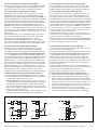
Aufbau, Klemmenbelegung/design, terminal assignment
LEDs
Konfigurationsschalter
Configuration switches
Anschluss ID-Sensor
ID Sensor connection
Klemmenleisten
Terminal strips
Anschluss PC
PC connection
Steckplatz für CMC600
Plug-in slot for CMC600
CAN
bus
“Host”
“Result 1”
“Sensor 1”
ID sensor
ID sensor
ID sensor
CDB650
CDB650
CDB650
Schema: Aufbau eines CAN-Sensor-Netzwerkes
Diagram: Building a CAN sensor network
Abb. 5: Belegung der Klemmen und Schalter/Fig. 5: Functional attribution of terminals and switches
6.5 Verdrahtung des CDB650
■ Elektroinstallation nur durch ausgebildetes Fachpersonal durch-
führen.
■ Bei Arbeiten in elektrischen Anlagen die gängigen Sicherheits-
vorschriften beachten.
■ Elektrische Verbindungen nur im spannungsfreien Zustand her-
stellen oder trennen.
■ Um den Kurzschluss-/Überlastungschutz der abgehenden Ver-
sorgungsleitungen (U
IN
*) zum ID-Sensor sicherzustellen, müssen
die verwendeten Aderquerschnitte unter Berücksichtigung der im
CDB650 eingebauten Sicherung ausgelegt werden.
Folgende Normen sind hierbei zu beachten: DIN VDE 0100 (Teil
430), DIN VDE 0298 (Teil 4) bzw. DIN VDE 0891 (Teil 1).
■ Klemmenbelegung siehe Anschlussbild unten oder im Deckel.
Anschlusspläne für Host-Schnittstelle/CAN-Schnittstelle/
Schaltein- und -ausgänge siehe Technische Information des
jeweiligen ID-Sensors.
■ Um Störeinflüsse zu vermeiden, Leitungen möglichst nicht
parallel zu Stromversorgungs- und Motorleitungen verlegen.
■ Gemeinsames Bezugspotenzial für alle Schalteingänge mit
Schalter S 3 (siehe Seite 2) wählen.
1. Den 17-pol. M12-Stecker des ID-Sensors über Leitung z. B.
Nr. 6051194 (3 m) mit der 17-pol. M12-Dose des CDB650
verbinden.
2. Alle anderen Leitungen über Kabel-Verschraubungen an den
Klemmen auflegen.
3. Optional: integrierte Triggereinheit für externe Beleuchtung des
LECTOR
65x beschalten. Siehe hierzu Kap. 6.6.2, Seite 7.
4 Anwenderseitige Schirmung am CDB650 auflegen (Klemme
„Shield“)
5. CAN-Bus: Falls CDB650 am Busende, Terminierungswiderstand
mit Schalter S 2 (siehe Seite 2) zuschalten.
Mit Konfigurationssoftware SOPAS ET ggf. den Ausgabestring an
die verdrahtete serielle Host-/CAN-Schnittstelle im ID-Sensor
zuweisen (siehe Online-Hilfe des ID-Sensors).
Hierzu PC mit 3-adriger RS-232-Datenleitung (Nullmodem-
leitung) an Stecker „AUX“ im CDB650 anschließen oder ID-
Sensor über Ethernet kontaktieren (abhängig v. Sensortyp).
6.5 Wiring the CDB650
■ Electrical installation should only be carried out by qualified
staff.
■ Observe the current safety regulations when working on
electrical systems.
■ Connect or disconnect current linkages only under de-energized
conditions.
■ To ensure that the outgoing supply cables (U
IN
*) to the ID sensor
are protected against short-circuits/overload, the wire cross-
sections must be dimensioned in accordance with the fuse
installed in the CDB650. The valid national standards must be
observed.
■ For terminal assignment, see connection diagram below or inside
the cover. For host/CAN interface/switching inputs/outputs
diagrams, see the Technical Information of the respective ID
sensor.
■ To prevent interference, do not lay cables parallel to power
supply or motor cables.
■ Choose combined reference potential for all switching inputs with
switch S 3 (see page 2).
1. Connect the 17-pin M12 male connector of the ID sensor to the
17-pin M12 female connector of the CDB650 using a suitable
cable, e.g. no. 6051194 (3 m).
2. Connect all other cables to the terminals provided using cable
glands.
3. Optional: Wire the integrated trigger unit for the external illumina-
tion of the LECTOR
65x. For details, see Chapter 6.6.2, Page 7.
4. Connect the shield of your system to the CDB650 (“Shield”
terminal).
5. CAN bus: if CDB650 is integrated at bus end, connect termina-
tion resistor with switch S 2 (see page 2).
Using SOPAS ET configuration software to assign the output data
string to the connected serial host/CAN interface in the ID
sensor, if required (see the online help of the ID sensor).
To do so, connect the PC to the “AUX” male connector on the
CDB650 using a 3-wire RS 232 data cable (null modem cable)
or establish communication to the ID sensor via Ethernet
(depends on sensor type).

7 # 88016155/XZ16/2013-12 © SICK AG · Germany · All rights reserved · Subject to change without notice · Irrtümer und Änderungen vorbehalten
6.6 Externe Beleuchtung für LECTOR
65x anschließen
Eine externe Beleuchtung, mit einem zum LECTOR
65x passenden
Versorgungsspannungsbereich, lässt sich am CDB650 wie folgt
anschließen, triggern und hierfür im LECTOR
65x aktivieren:
6.6.1 Beleuchtung mit Triggereingang anschließen
Die Beleuchtung (z. B. ICLxxx) muss zum Anschluss ein offenes
Leitungsende mit 3 Adern bieten: Versorgungsspannung, GND,
Triggereingang. Der Triggereingang der Beleuchtung wird direkt mit
dem Schaltausgang Res 2 oder Res 4 des LECTOR
65x im CDB650
beschaltet (Abb. 6a). Die Versorgung der Beleuchtung erfolgt ent-
weder über eine separate Fremdspannung V
s
mit Bezug auf GND
des CDB650 oder über die Versorgungsspannung, die an das
CDB650 angelegt wird. Bei Versorgung der Beleuchtung über die
Klemme U
in
* des CDB650 (intern mit Sicherung 2 A geschützt), darf
der Summenstrom alle Verbraucher (CDB650 intern, LECTOR
65x
inkl. Schaltausgang Res 2 oder Res 4 und Beleuchtung) 1,5 A nicht
überschreiten.
Beispiel: LECTOR
65x nimmt 1,05 A bei DC 19,2 V ohne Last an
seinen Schaltausgängen auf. 1,5 A minus 1,05 A ergibt für die
Beleuchtung einen max. verfügbaren Strom von 0,45 A.
Wird dagegen die nicht abgesicherte Klemme U
in
des CDB650
verwendet, muss die Versorgungsleitung der Beleuchtung kunden-
seitig entsprechend ihres Aderquerschnittes abgesichtert werden.
6.6.2 Beleuchtung ohne Triggereingang anschließen
Die Beleuchtung (z. B. VLR) bietet zum Anschluss ein offenes
Leitungsende mit nur 2 Adern: Versorgungsspannung, GND.
Zum Triggern der Beleuchtung wird deren Versorgungsspannung
über den Lastschalter der im CDB650 eingebauten Triggereinheit
ein- und ausgeschaltet (Abb. 6b). Der Schaltausgang Res 2 oder
Res 4 des LECTOR
65x bildet den Steuereingangsstromkreis für die
Triggereinheit. Die intern an der Triggereinheit anliegende Versor-
gungsspannung U
in
* ist mit der Sicherung 2 A des CDB650 abge-
sichert. Der Summenstrom für LECTOR
65x inkl. Schaltausgang
Res 2 oder Res 4 und Beleuchtung darf 1,5 A nicht überschreiten.
Beispiel: LECTOR
65x nimmt 1,05 A bei DC 19,2 V ohne Last an
seinen Schaltausgängen auf. 1,5 A abzüglich 1,05 A ergibt für die
Beleuchtung einen max. verfügbaren Strom von 0,45 A. Eine
Fremdspannung für die Beleuchtung kann nicht geschaltet werden.
6.6.3 Beleuchtungsansteuerung im LECTOR
65x aktivieren
1. Versorgungsspannung für CDB650 (LECTOR
65x) einschalten.
2. Mit der Konfigurationsoftware SOPAS ET, Option „Single Device“
im LECTOR
65x folgende Parameter setzen:
Schaltausgang Result 2 oder Result 4: E
XTERNE BELEUCHTUNG als
Lichtquelle wählen. Beleuchtungsmodell gemäß der vorliegenden
Beleuchtung (z. B. ICLxxx) wählen. Für andere Beleuchtungen
(z. B. VLR) das erforderliche Signal „aktiv low“ oder „aktiv high“
wählen. Hierbei zugleich den Betriebsmodus „durchgehend“ oder
„alternierend“ (blitzend) einstellen.
Für detaillierte Anleitung siehe Kapitel „Elektroinstallation“ in der
Technische Information LECTOR
65x (Artikel-Nr. 8016184).
6.6 Connecting an external illumination for LECTOR
65x
An external illumination with an suitable range of power supply
voltage regarding to the LECTOR
65x can be connected to the
CDB650, triggered and enabled in the LECTOR
65x as followed:
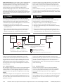
6.6.1 Connecting an illumination with trigger input
The connection for the illumination (e.g., ICLxxx) has to have an
open cable end with 3 wires: supply voltage, GND, trigger input.
The trigger input for the illumination is connected directly to the
switching output Res 2 or Res 4 of the LECTOR
65x in the CDB650
(Fig. 6a). Power is supplied to the illumination either via a separate
external voltage connected to the GND for the CDB650 or via the
supply voltage, which is connected to the CDB650. When powering
the illumination via the U
in
* terminal of CDB650 (internally pro-
tected with fuse 2 A), the total current of all consumers (CDB650
internal, LECTOR
65x including switching output Res 2 or Res 4
and illumination) must not exceed 1.5 A.
Example: LECTOR
65x draws a current of 1.05 A at DC 19.2 V
without load on the switching outputs. 1.5 A minus 1.05 A leads to
a maximum of 0.45 A available for the illumination.
However, if the U
in
terminal of the CDB650 that is not protected is
used, the supply line of the illumination has to be protected by the
customer according to the wire cross-section.
6.6.2 Connecting an illumination without trigger input
For connection, the illumination (e.g. VLR) has an open cable end
with only 2 wires: supply voltage, GND.
To trigger the illumination its supply voltage is switched on and off
via the load interrupter switch of the trigger unit integrated in the
CDB650 (Fig. 6b). The switching output Res 2 or Res 4 of the
LECTOR
65x forms the control input circuit for the trigger unit.
The U
in
* supply voltage connected internally to the trigger unit is
protected by the fuse 2 A of the CDB650. The total current for the
LECTOR
65x including switching output Res 2 and illumination
must not exceed 1.5 A.
Example: LECTOR
65x draws a current of 1.05 A at DC 19.2 V
without load on the switching outputs. 1.5 A minus 1.05 A leads to
a maximum of 0.45 A available for the illumination.
External voltage for the illumination cannot be switched.
6.6.3 Enabling the illumination control in the LECTOR
65x
1. Switch on the power supply voltage for CDB650 (LECTOR
65x).
2. Using the SOPAS ET configuration software with the “Single
Device” option to set the following parameters in LECTOR
65x:
Result 2 or Result 4 switching output: Select E
XTERNAL ILLUMINATION
for light source. Select the illumination model according to the
existing illumination (e.g. ICLxxx). For other illuminations (e.g.
VLR) select the required signal
ACTIVE LOW or ACTIVE HIGH. To do so,
select simultaneously the
CONTINUOUS or FLASHING mode.
For detailed instructions see Chapter “Electrical installation” in
the Technical Information LECTOR
65x (part no. 8016185).
Abb. 6: Anschluss einer externen Beleuchtung für LECTOR
65x (hier Result 2) am CDB650/Fig. 6: Connecting an external illumination for LECTOR
65x (here Result 2) to the CDB650
a) Beleuchtung mit Triggereingang/Ilumination with trigger input b) Beleuchtung ohne Triggereingang /Ilumination without trigger input
22
GND
52
TR
54
L+
21
Res/OUT 2
14
U
IN*
F
internal
CDB650
Zusätzlich verbinden!
To be connected
additionally!
(2 A)
22
GND
21
Res/OUT 2
14
U
IN*
GND
3
U
IN
F
GND
V
S
internal
F
external
LECTOR65x
CDB650 CDB650
Trigger
input
22
GND
21
Res/OUT 2
14
U
IN*
F
internal
Trigger
input
U
IN*
F
external
external
(2 A) (2 A)

8 # 8 8016155/XZ16/2013-12© SICK AG · Germany · All rights reserved · Subject to change without notice · Irrtümer und Änderungen vorbehalten
8016155/XZ16/2013-12 · MT_8M <PM 6.5> · Printed in Germany · Aftint40sw
SICK AG · Waldkirch · Germany
For local sales offices see www.sick.com
8. Fehlersuche
Störung
Nach Anlegen der Versorgungs-
spannung U
IN
leuchtet die LED
„Power“ (U
IN
*) nicht
Signale des angeschlossenen
Lesetakt-Sensors bleiben
wirkungslos
Nach Anschluss des PCs an
den Stecker „AUX“ kein Zu-
griff auf den Sensor mit Konfi-
gurationssoftware SOPAS ET
Abhilfe
Schalter S 1 (Power) in Position
„ON“ bringen
Lesetakt-Sensor gemäß Technischer
Information des ID-Sensors
anschließen
Schalters S 3 prüfen (SGND–GND)
Mit Konfigurationssoftware SOPAS
ET die Quelle des Lesetakts im ID-
Sensor auf „Sensor 1“ einstellen.
Download zum Sensor!
Wenn kein CMC600 gesteckt,
Schalter S 4 in Pos. „NO“ bringen
8. Troubleshoooting
Remedy
Set switch S 1 (Power) to “ON”
Connect reading pulse sensor in
accordance with the Technical
Information of the ID sensor
Check switch S 3 (SGND–GND)
Using SOPAS ET configuration
software, set the reading pulse
source on the sensor to “Sensor 1”
Perform a download to the sensor.
If no CMC600 is connected, set
switch S 4 to “NO”
Malfunction
“Power” LED (U
IN
*) does not
light up when power supply U
IN
is connected
Signals from connected reading
pulse sensor have no effect
Cannot access sensor with
SOPAS ET configuration software
after connecting the PC to the
"AUX" male connector
Typ CDB650-204 (Artikel-Nr. 1064114)
Optische Anzeigen 11 x LED
Elektrische Anschlüsse 1 x 17-pol. M12-Dose, A-codiert
1 x 9-pol. D-Sub-Stecker intern
Federkraftklemmen: 8 für Adern 0,14 mm
2
...
2,5 mm
2
/29 für Adern 0,14 mm
2
... 1 mm
2
Kabel-Verschraubungen 5 x M16, Klemmbereich 4,5 ... 10 (7) mm
Versorgungsspannung DC 10 V ... 30 V ...
SELV (EN 60950-1:2006-04) und
LPS (EN 60950-1: 2006-04) oder
Class 2 (UL 1310)
Leistungsaufnahme 1 W
Eingangsstrom Max. 2,4 A
2)
Triggereinheit Steuerstrom: 10 mA, Schaltstrom: siehe Kap. 6.6
Sicherung
3)
Flachstecksicherung MINI, 32 V, 2 A
Gehäuse Polycarbonat
Prüfzeichen CE, UL
Sicherheit EN 60950-1: 2006-04/A11: 2009-03/
A1: 2010-03
Schutzklasse III (EN 60950-1: 2006-04)
Schutzart IP 65
4)
(EN 60529/A1: 2002-02)
EMV-Prüfung EN 61000-6-2: 2005-08
EN 61000-6-3: 2007-01
Schwingfestigkeit EN 60068-2-6: 2008-02
Schockfestigkeit EN 60068-2-27: 2009-05
Gewicht Ca. 265 g (ohne optionales CMC600)
Umgebungs- Betrieb: –40 °C ... +50 °C
5)
temperatur Lager: –30 °C ... +75 °C
Rel. Luftfeuchtigkeit Max. 90 %, nicht kondensierend
1) Gültig bei entsprechender Gerätekennzeichnung auf dem Typenschild.
2) An Klemmen U
IN
. 3) Für Spannung U
IN
*, geschaltet über S 1 und interne Sicherung.
4) Schutzart nicht durch UL geprüft. 5) Betriebsumgebungstemperatur 0°C bis
–40 °C bei folgenden Bedingungen: Montage, elektrischer Anschluss sowie
Konfiguration/Power-up des Moduls über eingebaute Schalter nur im normalen
Betriebsum-gebungtemperaturbereich 0°C bis +50 °C. Einsatz bei Betriebs-
umgebungstemperatur 0°C bis –40 °C nur im Zustand der Ruhe (keine Montage-,
Anschluss- oder Konfigurationsarbeiten am Modul).
7. Technische Daten
7. Technical Data
Type CDB650-204 (part no. 1064114)
Visual indicators 11 x LEDs
Electrical connections 1 x 17-pin M12 female connector, A-coded
1 x 9-pin D Sub male connector, internal
Spring terminals: 8 for wires 0.14 mm
2
to 2.5
mm
2
and 29 for wires 0.14 mm
2
... 1 mm
2
Cable glands 5 x M16 for cables 4.5 mm ... 10 (7) mm
Power supply DC 10 V .... 30 V ...
SELV (EN 60950-1:2006-04) and
LPS (EN 60950-1: 2006-04) or
Class 2 (UL 1310)
Power consumption 1 W
Input current Max. 2.4 A
2)
Trigger unit Control current: 10 mA, load current: see Chapter 6.6
Fuse
3)
Blade-type fuse MINI, 32 V, 2 A
Housing Polycarbonate
Conformity CE, UL
Safety EN 60950-1: 2006-04/A11: 2009-03/
A1: 2010-03
Protection class III (EN 60950-1: 2006-04)
Enclosure rating IP 65
4)
(EN 60529/A1: 2002-02)
EMC tested EN 61000-6-2: 2005-08
EN 61000-6-3: 2007-01
Vibration EN 60068-2-6: 2008-02
Shock EN 60068-2-27: 2009-05
Weight Approx. 265 g (without optional CMC600)
Ambient Operation: –40 °C ... +50 °C
5)
temperature Storage: –30°C ... +75 °C
Rel. air humidity Max. 90%, non-condensing
1) Valid with corresponding product marking on the nameplate.
2) On terminals U
IN
. 3) For voltage U
IN
*, switched via S 1 and internal fuse.
4) Enclosure rating not tested by UL. 5) Temperature range 0°C to –40 °C at the
following conditions: Installation, electrical connection as well as configuration/
power-up of the module using built-in switches only at normal operation ambient
temperature range of 0°C to +50 °C. Application of the module at operation
ambient temperature only in rest status (without any mounting, electrical
installation or configuration works on the module).
-
 1
1
-
 2
2
-
 3
3
-
 4
4
-
 5
5
-
 6
6
-
 7
7
-
 8
8


in anderen Sprachen
- English: SICK CDB650 Operating instructions
Verwandte Artikel
-
SICK CDB620 Connection Module Bedienungsanleitung
-
-
-
-
-
SICK Panorama mirror hood for Lector ® 64x/65x Mounting instructions
-
-
-
-