SICK Panorama mirror hood for Lector ® 64x/65x Mounting instructions
- Typ
- Mounting instructions

8017697/2014-10-17 • Subject to change without notice • Irrtümer und Änderungen vorbehalten • © SICK AG • Germany • www.sick.com 1
Spiegelhaube Panorama
für Lector
®
64x/65x
Montageanleitung
1 Bestimmungsgemäße Verwendung
Die Spiegelhaube Panorama ist ein Zubehör für die kamerabasier-
ten Codeleser der Produktfamilien Lector
®
64x und Lector
®
65x.
Sie unterstützt die Varianten Lector
®
64x Flex, Lector
®
65x Flex und
Lector
®
65x Dynamic Focus. Die Spiegelhaube dient zur Verbreite-
rung des Sichtfeldes des eingesetzten Lector. Sie wird zusammen
mit dem Lector entweder für die Toplesung oder Seitenlesung mon-
tiert. In dieser Kombination dient der Lector
zur automatischen,
stationären Erfassung und Dekodierung von Codes auf bewegten
Objekten. Im Folgenden wird der Lector vereinfacht als „Lector“
bezeichnet, außer an Stellen, an denen eine Unterscheidung der
Varianten erforderlich ist.
Kombinationsmöglichkeiten Spiegelhaube und Lector
Spiegelhaube
Artikelnummer
1)
Lector
2076621 • Lector
®
65x Flex, Objektiv: 25 mm
2076622 • Lector
®
64x Flex, Objektiv: 35 mm
• Lector
®
65x Flex, Objektiv: 35 mm
2076623 • Lector
®
64x Flex, Objektiv: 50 mm
• Lector
®
65x Flex, Objektiv: 50 mm
• Lector
®
65x Dynamic Focus, Objektiv: 54 mm
1) Artikelnummer siehe Typenschild. - Für die Position Typenschild siehe Kapitel 13
„Geräteaufbau und Abmessungen“ auf Seite 10.
Zu diesem Dokument
Die Montageanleitung beschreibt die Montage der Spiegelhaube
und die Inbetriebnahme der Spiegelhaube zusammen mit einem
Lector.
Panorama mirror hood for
Lector
®
64x/65x
Mounting instructions
1 Correct use
The Panorama mirror hood is an accessory for image-based code
readers from the Lector
®
64x and Lector
®
65x product families.
It is suitable for use with the Lector
®
64x Flex, Lector
®
65x Flex, and
Lector
®
65x Dynamic Focus variants. The purpose of the mirror
hood is to widen the eld of view of the Lector used. Together with
the Lector, it is either mounted for top reading or side reading.
In this combination, the Lector can be used for automatic, xed
identication and decoding of bar codes on moving objects. In this
document, the Lector is simply referred to as the ‘Lector’, unless a
clear distinction needs to be made between variants.
Possible combinations of mirror hood and Lector
Mirror hood
part number
1)
Lector
2076621 • Lector
®
65x Flex, lens: 25 mm
2076622 • Lector
®
64x Flex, lens: 35 mm
• Lector
®
65x Flex, lens: 35 mm
2076623 • Lector
®
64x Flex, lens: 50 mm
• Lector
®
65x Flex, lens: 50 mm
• Lector
®
65x Dynamic Focus, lens: 54 mm
1) For part number, see type label. - For the position of the type label, see Chapter
13 „Device structure and dimensions“ on Page 10.
About this document
These mounting instructions describe how to mount the mirror
hood and how to commission the mirror hood together with a
Lector.

2 8017697/2014-10-17 • Subject to change without notice • Irrtümer und Änderungen vorbehalten • © SICK AG • Germany • www.sick.com
Ergänzende und mitgeltende Dokumente
Weiterführende Informationen wie z. B. zur Bedienung und zu den
Technischen Daten des Lector nden Sie in der jeweiligen Betriebs-
anleitung.
■ Lector
®
64x Flex (Nr. 8017446)
■ Lector
®
65x Flex (Nr. 8016180)
■ Lector
®
65x Dynamic Focus (Nr. 8016182)
Die Dokumente sind als PDF auf den SICK-Produktseiten des
Lector im Web zugänglich:
www.mysick.com/de/lector/65x
www.mysick.com/de/lector/64x
2 Zu Ihrer Sicherheit
■ Lesen Sie diese Anleitung aufmerksam vor der Montage der
Spiegelhaube durch, um mit der Spiegelhaube und ihrer Funkti-
on vertraut zu werden. Die Anleitung als Bestandteil des Gerä-
tes in unmittelbarer Nähe der Spiegelhaube jederzeit zugänglich
aufbewahren!
■ Der Lector
®
entspricht typabhängig der LED-Risikogruppe RG 1
oder RG 2 und der Laserklasse 1M. - Gefahren und Schutz-
maßnahme siehe folgenden Warnhinweise „Optische Strah-
lung“.
■ Montieren Sie den Lector
nur bei ausgeschalteter Versorgungs-
spannung.
■ Beachten Sie den Abschnitt „Zu Ihrer Sicherheit“ in der jeweili-
gen & Betriebsanleitung des Lector.
a VORSICHT
Optische Strahlung des Lector
®
64x/65x!
Laserstrahlung Klasse 1M
Die zugängliche Strahlung des Ziellasers stellt aufgrund von
normalen Einschränkungen durch das menschliche Verhalten
keine Gefahr dar.
LED-Risikogruppe 1
Die zugängliche Strahlung der Beleuchtung (RG 1) stellt aufgrund
von normalen Einschränkungen durch das menschliche Verhal-
ten keine Gefahr dar.
LED-Risikogruppe 2
Die zugängliche Strahlung der Beleuchtung (RG 2) stellt aufgrund
von Abwendungsreaktionen bei sehr hellen Lichtquellen sowie
Temperaturempnden keine Gefahr dar.
Für beide Strahlungsarten
Vorübergehende, irritierende optische Wirkungen auf das
menschliche Auge (z. B. Blendung, Blitzblindheit, Nachbilder,
Beeinträchtigung des Farbsehens) können, insbesonders bei
niedriger Umfeldhelligkeit, nicht gänzlich ausgeschlossen wer-
den. Schutzvorkehrungen sind nicht erforderlich.
Vorsicht – wenn andere als die hier angegebenen Bedienungs-
oder Justiereinrichtungen benutzt oder andere Verfahrensweisen
ausgeführt werden, kann dies zu gefährlicher Strahlungseinwir-
kung führen.
> Nicht in die eingeschaltete Lichtquelle blicken.
> LED Risikogruppe 2: ACHTUNG – möglicherweise gefährliche
optische Strahlung. Bei Betrieb nicht absichtlich für längere
Zeit in die Beleuchtung blicken. Eine Schädigung der Augen
ist möglich. Mitgeliefertes Warnschild an einer gut sichtbaren
und sinnvollen Stelle auf die Spiegelhaube aufkleben.
> Laser nicht direkt mit optischen Instrumenten (Lupe, Mikros-
kop) betrachten.
> Gültige Bestimmungen zur photobiologischen Sicherheit von
Lampen und Lampensystemen sowie zum Laserschutz in ihrer
neuesten Fassung beachten
> Der Betrieb mit externen Beleuchtungen kann zu Überschrei-
tung der hier beschriebenen Risiken führen und ist fallabhän-
gig durch den Anwender zu betrachten.
Supplementary and other relevant documents
Additional information, for example regarding the operation and
technical data of the Lector, can be found in the relevant operating
instructions.
■ Lector
®
64x Flex (No. 8017447)
■ Lector
®
65x Flex (No. 8016181)
■ Lector
®
65x Dynamic Focus (No. 8016183)
The documents are available on the web in PDF format. Simply visit
the SICK product page for the Lector:
www.mysick.com/en/lector/65x
www.mysick.com/en/lector/64x
2 Safety information
■ Read these instructions carefully before mounting the mirror
hood in order to familiarize yourself with the device and its func-
tions. The operating instructions form a part of the device and
must be kept in the immediate vicinity of the mirror hood where
they can be accessed at all times!
■ Depending on the model, the Lector
®
falls into LED risk group
RG 1 or RG 2 and laser class 1M. - For risks and protective
measures, see the following ‘optical beam’ warning.
■ Only mount the Lector when the supply voltage is switched off.
■ Take note of the ‘For your safety’ section found in the relevant
& Lector operating instructions.
a CAUTION
Optical beam of the Lector
®
64x/65x!
Laser beam class 1M
The accessible beam from the targeting laser does not represent
a risk due to the normal restrictions imposed by human behavior.
LED risk group 1
The accessible beam from the illumination unit (RG 1) does
not represent a risk due to the normal restrictions imposed by
human behavior.
LED risk group 2
The accessible beam from the illumination unit (RG 2) does not
represent a risk due to aversion responses to very bright light
sources and the perception of heat.
For both types of beam
It is not possible to entirely rule out temporary, disorientating
optical effects on the human eye (e.g. dazzle, ash blindness, af-
terimages, impairment of color vision), particularly in conditions
of dim lighting. No safety precautions are required.
Caution – if any operating or adjusting devices other than those
specied here are used or other methods are employed, this can
lead to dangerous exposure to radiation.
> Do not look into the light source when it is switched on.
> LED risk group 2: WARNING – potentially dangerous optical
beam. Do not deliberately look into the illumination unit for a
long time when in operation. Damage to the eyes is possible.
Place the warning label provided in a visible, obvious place on
the mirror hood.
> Do not view the laser directly with optical instruments (e.g.
magnifying glass, microscope).
> Observe the latest version of the applicable regulations on
photobiological safety of lamps and lamp systems as well as
on laser protection.
> If the product is operated in conjunction with external illumi-
nation systems, the risks described here may be exceeded.
This must be taken into consideration by users on a case-by-
case basis.

8017697/2014-10-17 • Subject to change without notice • Irrtümer und Änderungen vorbehalten • © SICK AG • Germany • www.sick.com 3
Beleuchtung mit LEDs der Risikogruppe 2 (Blau – Narrow)
Dieser Beleuchtungsvariante liegt ein schwarz-gelbes, selbstkle-
bendes Warnschild für sichtbare optische Strahlung bei.
Abb. 1: Warnschild für LEDs der Risikogruppe 2
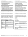
3 Funktionsweise
Die Spiegelhaube verbreitert das Sichtfeld des eingesetzten Lector.
Hierzu wird das Sichtfeld in der Richtung des Förderbands geteilt
und in nebeneinander liegende Teil-Sichtfelder umgelenkt.
12
33
4
5
5
Abb. 2: Funktionsweise Spiegelhaube,
Lector und Spiegelhaube für Toplesung montiert
1. Lector
ohne Spiegelhaube
2. Lector
mit Spiegelhaube
3. Förderband
4. Sichtfeld Lector
ohne Spiegelhaube
5. Teil-Sichtfeld Lector
mit Spiegelhaube
4 Transport und Lagerung
- Für den Transport und die Lagerung des Lector siehe jeweilige
& Betriebsanleitung.
■ Die Spiegelhaube in der Originalverpackung transportieren und
lagern.
■ Nicht im Freien aufbewahren.
■ Keinen aggressiven Medien (z. B. Lösungsmittel wie Azeton)
aussetzen.
■ Lagerbedingungen: trocken, staubfrei, keine direkte Sonnen-
einstrahlung, Lagertemperatur –20 °C bis 70 °C, möglichst
erschütterungsfrei, relative Luftfeuchte max. 90 % (nicht kon-
densierend).
■ Um eine Beschädigung der Spiegel in der Spiegelhaube zu
vermeiden, Schutzfolie erst direkt vor der Inbetriebnahme
abziehen. - Siehe Kapitel 8.1 „Schutzfolie von den Spiegeln
abziehen“ auf Seite 6.
5 Lieferumfang
■ Spiegelhaube Panorama inkl. 4 vormontierten Befestigungs-
schrauben für den Lector und 4 Bohrungen zur Befestigung der
Spiegelhaube. Die Schrauben für die Spiegelhaube sind nicht im
Lieferumfang enthalten.
■ Gedruckte Montageanleitung Deutsch/Englisch (Nr. 8017697)
Illumination unit with LEDs in risk group 2 (blue – narrow)
This illumination unit variant comes with a black and yellow self-ad-
hesive warning label for visible optical radiation.
Fig. 1: Warning label for LEDs in risk group 2
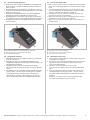
3 Functionality
The mirror hood widens the eld of view of the Lector in use. In
order to do so, the eld of view in the direction of the belt is split,
and deected into adjacent partial elds of view.
12
33
4
5
5
Fig. 2: Operation of mirror hood, Lector, and mirror hood mounted for top reading
1. Lector without mirror hood
2. Lector with mirror hood
3. Belt
4. Field of view of Lector without mirror hood
5. Partial eld of view of Lector with mirror hood
4 Transport and storage
- For transport and storage of the Lector, see the relevant
& operating instructions.
■ The mirror hood must be transported and stored in its original
packaging.
■ Do not store outdoors.
■ Do not expose to aggressive media (e.g., solvents such as
acetone).
■ Storage conditions: dry, dust-free, no direct sunlight, storage
temperature –20 °C to 70 °C, as little vibration as possible,
relative air humidity max. 90% (non-condensing).
■ In order to prevent damage to the mirrors in the mirror hood, do
not remove the protective lm until immediately before commis-
sioning. - See Chapter 8.1 „Removing the protective lm from
the mirrors“ on Page 6.
5 Scope of delivery
■ Panorama mirror hood including four pre-mounted xing screws
for the Lector and four xing holes for mounting the mirror hood.
The screws for the mirror hood are not included in the scope of
delivery.
■ Printed mounting instructions German/English (No. 8017697)

4 8017697/2014-10-17 • Subject to change without notice • Irrtümer und Änderungen vorbehalten • © SICK AG • Germany • www.sick.com
6 Montage
a VORSICHT
Scharfe Kanten an den eingebauten Spiegeln!
Scharfe Kanten können zu Schnittverletzungen führen.
> Nicht in die Spiegelhaube fassen.
6.1 Erforderliche Hilfsmittel
■ 2 Schrauben M6 zur Befestigung der Spiegelhaube an einer
kundenseitig gestellten Halterung bzw. Prolsystem (Nutenstei-
ne). Schraubenlänge abhängig vom Montageuntergrund.
■ Schraubzwingen und/oder Kabelbinder, um die Spiegelhaube
provisorisch während der Montage am Montageort zu xieren.
6.2 Montageanforderungen
■ Stabile Halterung bzw. stabiles Profilsystem mit ausreichender
Tragkraft und passenden Maßen für die Spiegelhaube und den
Lector. Das Gesamtgewicht für Lector und Spiegelhaube beträgt
ca. 3,5 kg - Abmessungen siehe Kapitel 13 „Geräteaufbau und
Abmessungen“ auf Seite 10.
■ Erschütterungs- und schwingungsfreie Befestigung
■ Weitere Montageanforderung für den Lector: - Siehe jeweilige
& Betriebsanleitung.
6.3 Anwendungsbeispiele
Die Spiegelhaube können Sie für Toplesungen oder Seitenlesungen
einsetzen.
1
2
Abb. 3: Beispiel für eine Toplesung
1. Pfeil „conveying direction“: In Richtung des Förderbandes
2. Kerbe: Mittig zur Sichtfeldbreite
Abb. 4: Beispiel für eine Seitenlesung
6 Mounting
a CAUTION
The mounted mirrors have sharp edges!
Sharp edges can cause cuts.
> Do not place hands inside the mirror hood.
6.1 Equipment required
■ 2 x M6 screws for mounting the mirror hood on a bracket or pro-
le system (sliding nuts) supplied by the customer. Screw length
depends on the mounting surface.
■ Screw clamps and/or cable ties to temporarily attach the mirror
hood to the mounting location during mounting.
6.2 Mounting requirements
■ Sturdy bracket or profile system with sufficient load-bearing
capacity and suitable dimensions for the mirror hood and the
Lector. The total weight of the Lector and mirror hood stands
at approx. 3.5 kg - For dimensions, see Chapter 13 „Device
structure and dimensions“ on Page 10.
■ Shock- and vibration-free mounting
■ Additional mounting requirement for the Lector: - See the
relevant
& operating instructions.
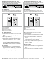
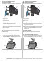
6.3 Example applications
You can use the mirror hood for top reading or side reading.
1
2
Fig. 3: Example of top reading
1. ‘Conveying direction’ arrow: in direction of the belt
2. Notch: in the center of the eld of view
Fig. 4: Example of side reading

8017697/2014-10-17 • Subject to change without notice • Irrtümer und Änderungen vorbehalten • © SICK AG • Germany • www.sick.com 5
6.4 Hinweise zur Montageposition
■ Beachten Sie, dass Sie ggf. den Montageort der Spiegelhaube
für ein besseres Leseergebnis während der Ausrichtung noch
ändern müssen.
■ Der Montageabstand der Spiegelhöhe zum Barcode muss zum
ermittelten Leseabstand passen. - Siehe Kapitel 14 „Sichtfeld-
diagramme“ auf Seite 11.
■ Die maximale Codegröße darf die in dem Sichtfelddiagramm
angegebene maximale Codegröße nicht überschreiten.
■ Die Spiegelhaube so ausrichten, dass der Pfeil auf der Haube
„conveying direction“ der Richtung des Förderbandes entspricht.
■ Die Kerbe in der Haube der Spiegelhaube mittig zur Sichtfeld-
breite ausrichten.
2
3
1
Abb. 5: Merkmale Spiegelhaube für die Ausrichtung
1. Befestigungsbohrungen für die Spiegelhaube für die Seitenlesung
2. Pfeil „conveying direction“: In Richtung des Förderbandes
3. Kerbe: Mittig zur Sichtfeldbreite
6.5 Spiegelhaube montieren
1. Montageabstand ermitteln. - Siehe Kapitel 14 „Sichtfelddia-
gramme“ auf Seite 11.
2. Spiegelhaube platzieren und über Schraubzwingen oder
Kabelbinder provisorisch am Montageort xieren. Hinweise zur
Montageposition beachten.
3. Spiegelhaube mit mindestens 2 Schrauben befestigen.
Bei Seitenlesung die unteren Bohrungen verwenden. - Siehe
Abb. 5.
4. Bei Varianten des Lector mit Beleuchtung mit LEDs der Risiko-
gruppe 2 (Blau – Narrow) liegt ein schwarz-gelbes, selbstkle-
bendes Warnschild für sichtbare optische Strahlung bei.
- Siehe Abb. 1 auf Seite 3. Warnschild an einer gut sicht-
baren und sinnvollen Stelle auf die Spiegelhaube aufkleben.
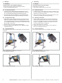
6.4 Notes on mounting position
■ Bear in mind that you may have to change the mounting location
of the mirror hood during alignment to achieve a better reading
result.
■ The mounting distance between the mirrors and the bar code
must correspond with the working distance calculated. - See
Chapter 14 „Field of view diagrams“ on Page 11.
■ The maximum code size may not exceed the maximum code
size stated in the eld of view diagram.
■ Align the mirror hood so that the ‘conveying direction’ arrow on
the hood is in line with the direction of the belt.
■ Align the notch in the mirror hood so that it is in the center of
the eld of view.
2
3
1
Fig. 5: Features of the mirror hood used for alignment
1. Fixing holes for mirror hood for side reading
2. ‘Conveying direction’ arrow: in direction of the belt
3. Notch: in the center of the eld of view
6.5 Mounting the mirror hood
1. Determine the mounting distance. - See Chapter 14 „Field of
view diagrams“ on Page 11.
2. Position the mirror hood and temporarily attach it to the mount-
ing location using screw clamps or cable ties. Refer to the
notes on mounting position.
3. Mount the mirror hood with at least two screws.
In the case of side reading, use the lower xing holes. - See
Fig. 5.
4. In the case of variants of the Lector with an illumination unit
containing LEDS from risk group 2 (blue – narrow), a black
and yellow adhesive warning label for visible optical beams is
provided.
- See Fig. 1 on Page 3. Place the warning label provided
in a visible, obvious place on the mirror hood.

6 8017697/2014-10-17 • Subject to change without notice • Irrtümer und Änderungen vorbehalten • © SICK AG • Germany • www.sick.com
6.6 Lector an die Spiegelhaube montieren
Lector
®
64x/65x Flex montieren
Voraussetzung: Das Optik-Kit ist vollständig auf dem Gehäuse des
Lector
montiert.
3
1
2
4
Abb. 6: Lector
®
64x/65x Flex in die Spiegelhaube montieren
1. Spiegelhaube Panorama
2. Optik-Schutzhaube
3. Lector
®
64x/65x Flex, Gehäuse mit Optik-Kit ohne Optik-Schutzhaube
4. Befestigungsschrauben (4x)
1. Optik-Schutzhaube vom Lector
®
64x/65x Flex demontieren.
2. Lector
®
64x/65x Flex mittels den 4 vormontierten Befestigungs-
schrauben an die Spiegelhaube montieren.
Lector
®
65x Dynamic Focus
> Lector
®
65x Dynamic Focus mittels den 4 vormontierten Befesti-
gungsschrauben an die Spiegelhaube montieren. Optik-Schutz-
haube nicht entfernen!
7 Elektrische Installation
- Für den elektrischen Anschluss des Lector siehe jeweilige
& Betriebsanleitung.
8 Inbetriebnahme und Konguration
8.1 Schutzfolie von den Spiegeln abziehen
> Schutzfolien von den beiden Spiegeln in der Spiegelhaube
abziehen. Nicht entfernte Schutzfolien führen zu einer Beein-
trächtigung der Bildqualität. Spiegelächen danach nicht mehr
berühren.
1
1
Abb. 7: Schutzfolien von den Spiegeln abziehen
1. Schutzfolie
6.6 Mounting the Lector on the mirror hood
Mounting the Lector
®
64x/65x Flex
The optics kit must be completely mounted on the housing of the
Lector rst.
3
1
2
4
Fig. 6: Mounting the Lector
®
64x/65x Flex on the mirror hood
1. Panorama mirror hood
2. Optics protective hood
3. Lector
®
64x/65x Flex, housing with optics kit without optics protective hood
4. Fixing screws (4x)
1. Disassemble the optics protective hood of the
Lector
®
64x/65x Flex.
2. Mount the Lector
®
64x/65x Flex on the mirror hood using the
four pre-mounted xing screws.
Lector
®
65x Dynamic Focus
> Mount the Lector
®
65x Dynamic Focus on the mirror hood using
the four pre-mounted xing screws. Do not remove the optics
protective hood!
7 Electrical installation
- For electrical connection of the Lector, see the relevant
& operating instructions.
8 Commissioning and conguration
8.1 Removing the protective lm from the mirrors
> Remove the protective lm from both mirrors in the mirror hood.
Not removing the protective lm can impair image quality. Do
not touch the mirror surfaces again after this.
1
1
Fig. 7: Removing the protective lm from the mirrors
1. Protective lm

8017697/2014-10-17 • Subject to change without notice • Irrtümer und Änderungen vorbehalten • © SICK AG • Germany • www.sick.com 7
8.2 Kongurationssoftware installieren, starten und einrichten
Die Inbetriebnahme und die Konguration des Lector erfolgt stan-
dardmäßig mit der Kongurationssoftware SOPAS ET.
1. Kongurationssoftware SOPAS ET installieren und starten.
- Siehe jeweilige
& Betriebsanleitung des Lector. Beim Star-
ten bei der Frage „Standard-Benutzeroberäche öffnen?“ auf
„Nein“ klicken.
2. Für eine bessere Übersicht unterhalb der Menüzeile auf das
Icon „2 Fenster vertikal“ klicken.
3. In der Baumstruktur das Menü Kamera und Beleuchtung wählen
(Menüpfad: Parameter > leseKonfiguration > Kamera und Beleuch-
tung).
4. Menü
Kamera und Beleuchtung in das rechte Fenster ziehen.
5. Standardmäßig ist in SOPAS ET die Option „1D-Code“ aktiviert.
Ggf. in der Baumstruktur über das Menü codeKonfiguration den
passenden Code kongurieren (Menüpfad:
Parameter > codeKon-
figuration).
6. Im rechten Fenster, Bereich Performance steigern die Option
Panorama mode aktivieren.
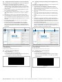
7. Im Fenster online-Bilder die Schaltäche einrichten klicken.
Der Lector nimmt nun fortlaufend Bilder auf und dekodiert
diese mit den aktuellen Einstellungen. Die Auswirkungen der
Objektiveinstellung sowie von Parameteränderungen macht er
so sichtbar.
312
Abb. 8: Beispiel für eine Online-Bilddarstellung in SOPAS ET
1. Menübaumstruktur
2. Online-Bilddarstellung
3. Rechtes Fenster mit Menü Kamera und Beleuchtung
8.3 Lector
®
64x/65x Flex kongurieren
1. Testcode platzieren:
• zwischen den beiden roten Ziellasern
• bei Toplesung auf ein mittelhohes Objekt, bei Seitenlesung
auf ein Objekt im mittleren Leseabstand.
Test Code
Abb. 9: Test-Code zur Einstellung der Schärfe
8.2 Installing, launching and setting up the conguration soft-
ware
The SOPAS ET conguration software is used as standard for com-
missioning and conguration the Lector.
1. Install and launch the SOPAS ET conguration software.
- See the relevant
& operating instructions for the Lector.
When launching, click ‘No’ in response to the ‘Open the stan-
dard user interface?’ prompt.
2. For a better view below the menu bar, click on the ‘Vertically
split’ icon.
3. In the tree structure, select the camera and illumination menu
(menu path:
settings > reading configuration > camera and illumi-
nation).
4. Drag the
camera and illumination menu into the right-hand win-
dow.
5. In SOPAS ET, the option ‘1D-Code’ is activated by default. If
necessary, congure the correct code in the tree structure via
the
code config menu (menu path: Parameters > code config).
6. In the right-hand window, in the
increase Performance area, acti-
vate the Panorama mode option.
7. In the
online image window, click the edit button. The Lector now
starts recording images consecutively and uses the current
settings to decode them. The effects of any lens adjustment or
parameter changes are thus directly visible.
312
Fig. 8: Example of online image display in SOPAS ET
1. Menu tree structure
2. Online image display
3. Right-hand window with camera and illumination menu
8.3 Conguring the Lector
®
64x/65x Flex
1. Place the test code:
• between the two red targeting lasers
• in the case of top reading, on an object of medium height,
and in the case of side reading, on an object at a medium
working distance.
Test Code
Fig. 9: Test code for adjusting sharpness

8 8017697/2014-10-17 • Subject to change without notice • Irrtümer und Änderungen vorbehalten • © SICK AG • Germany • www.sick.com
2. Die Blende über den Blendenring am Lector
®
64x/65x Flex auf
einen niedrigen Wert wie z. B. „2“ einstellen.
3
12
4
Abb. 10: Blendenring und Schärfering am Lector
®
64x/65x
1. Schärfering
2. Blendenring
3. Stellschraube zum Arretieren des Blendenrings
4. Stellschraube zum Arretieren des Schärferings
3. Belichtungszeit und helligKeit soweit reduzieren, bis der Test-
Code im Bild gut sichtbar ist.
4. Die Option schärfemessung anzeigen aktivieren.
5. Die Bildschärfe über den Schärfering am Lector
®
64x/65x Flex
so scharf stellen, dass der Schärfe-Diagnosebalken den obe-
ren Anschlag erreicht. Die Kanten müssen gut sichtbar sein.
6. Schärfering über Stellschraube arretieren.
7. Objekt mit Test-Code entfernen.
8. Einstellungen mit Test-Code prüfen. Blende auf einen höheren
Wert wie z.B. „8“ einstellen. Ggf. für mehr Schärfentiefe, einen
Wert größer „8“ einstellen. Beachten Sie, dass bei größerer
Blendenzahl die Bildhelligkeit geringer ist und per Software die
Bildhelligkeit über den Schieberegler helligKeit erhöht werden
muss. Dies reduziert die Bildqualität.
9. Blendenring über Stellschraube arretieren.
10. Im Bildanzeigefenster (online-Bilder) die Schaltäche BetrieB
klicken und die Einstellungen im Lesebetrieb mit verschieden
Objekthöhen bzw. Objekttiefen (Realbetrieb) testen.
11. Einstellungen für weitere Funktionen im geplanten Betrieb wie
Code, Lesetaktung, Leseergebnisformate, Datenschnittstelle
etc. vornehmen.
12. Konguration speichern. - Siehe jeweilige & Betriebsanlei-
tung des Lector.
Optik-Schutzhaube des Lector
®
64x/65x Flex montieren
> Optik-Schutzhaube auf das Gehäuse des Lector montieren.
8.4 Lector
®
65x Dynamic Focus kongurieren
Leseeigenschaften mit dem Assistenten kongurieren
> Den Assistenten
auto-setuP im Programmfenster links starten
und dem Dialog folgen.
Der Lector
®
65x Dynamic Focus stellt sich mit dem Auto-Setup
automatisch auf die Lichtverhältnisse, den Leseabstand und
die Qualität eines präsentierten Codes (nicht gültig für Pharma-
code) ein. Die ermittelten Werte für die Parameter speichert der
Lector vorerst temporär ab. SOPAS ET übernimmt die Parameter
für die Menüs Kamera und Beleuchtung und codeKonfiguration.
Konguration fortführen und beenden
1. Um den Lector
®
65x Dynamic Focus individuell in den Bild- und
Codeeinstellungen zu optimieren, die Parameterwerte in den
Menüs Kamera und Beleuchtung und codeKonfiguration anpassen.
2. Im Bildanzeigefenster (online-Bilder) die Schaltäche BetrieB
klicken und die Einstellungen im Lesebetrieb mit verschieden
Objekthöhen bzw. Objekttiefen (Realbetrieb) testen.
3. Konguration ggf. speichern. - Siehe jeweilige & Betriebsan-
leitung des Lector
.
2. Adjust the mask using the aperture ring on the Lector
®
64x/65x
Flex to a low value such as ‘2’.
3
12
4
Fig. 10: Aperture ring and sharpness ring on the Lector
®
64x/65x
1. Sharpness ring
2. Aperture ring
3. Set screw for clamping the aperture ring
4. Set screw for clamping the sharpness ring
3. reduce the shutter time and Brightness until the test code is clearly
visible on the image.
4. Activate the disPlay sharPness option.
5. Increase the image sharpness using the sharpness ring on the
Lector
®
64x/65x Flex until the sharpness diagnosis bar reaches
the upper stop position. The edges must be clearly visible.
6. Clamp the sharpness ring using set screws.
7. Remove the object with the test code on it.
8. Check the test code settings. Adjust the mask to a higher
value, such as ‘8’. If a greater depth of eld is required, select
a value higher than ‘8’. Bear in mind that using a greater mask
value reduces image brightness, meaning that brightness must
be increased using the Brightness slider in the software. This
reduces image quality.
9. Clamp the aperture ring using set screws.
10. Go to the image display window (online images), click the oPera-
tion button and test the settings in read mode (real operation)
using varying object heights and depths.
11. Make settings for additional functions during planned oper-
ation such as codes, reading clock, read result formats, data
interface, etc.
12. Save the conguration. - See the relevant & operating in-
structions for the Lector.
Mounting the optics protective hood of the Lector
®
64x/65x Flex
> Mount the optics protective hood on the Lector housing.
8.4 Conguring the Lector
®
65x Dynamic Focus
Conguring reading performance with the Wizard
> Start the
auto-setuP wizard on the left in the program window
and follow the instructions in the dialog box.
The Lector
®
65x Dynamic Focus uses the Auto-Setup function to
adjust itself automatically to suit the lighting conditions, reading
distance, and quality of the code presented (not applicable
to the Pharmacode standard). The values calculated for the
settings are stored temporarily by the Lector at rst. SOPAS ET
applies the parameters to the camera and illumination and code
config menus.
Continuing and quitting conguration
1. For custom optimization of the image and code settings of the
Lector
®
65x, adjust the parameter values in the camera & illumi-
nation and code config menus.
2. Go to the image display window (online images), click the oPera-
tion button and test the settings in read mode (real operation)
using varying object heights and depths.
3. Save the conguration if necessary. - See the relevant
& operating instructions for the Lector.

8017697/2014-10-17 • Subject to change without notice • Irrtümer und Änderungen vorbehalten • © SICK AG • Germany • www.sick.com 9
9 Wartung und Pege
- Für die Wartung und Pege des Lector siehe jeweilige & Be-
triebsanleitung.
a VORSICHT
Scharfe Kanten an den montierten Spiegeln!
Scharfe Kanten können zu Schnittverletzungen führen.
> Nicht in die Spiegelhaube fassen.
HINWEIS
Mögliche Beschädigung der Spiegelächen!
Durch eine falsche Reinigungstechnik oder durch aggressive Rei-
nigungsmittel können die Spiegel beschädigt und die Leseeigen-
schaften des Lector beeinträchtigt werden.
> Spiegelächen nicht berühren. Ggf. für die Reinigung Baum-
wollhandschuhe anziehen.
> Spiegel mit einem fusselfreien und trockenen Tuch reinigen.
> Beim Reinigen kein Druck auf die Spiegel ausüben.
Wichtig!
Sind die Spiegel zerkratzt oder beschädigt (Sprung, Bruch), muss
die Spiegelhaube ausgewechselt werden.
10 Reparatur
- Für die Reparatur des Lector siehe jeweilige & Betriebsanlei-
tung.
11 Demontage und Entsorgung
- Für die Demontage und Entsorgung des Lector siehe jeweilige
& Betriebsanleitung.
Spiegelhaube umweltgerecht gemäß den jeweils gültigen länder-
spezischen Abfallbeseitigungsvorschriften entsorgen.
Die SICK AG nimmt derzeit keine unbrauchbar gewordenen Geräte
zurück.
12 Technische Daten
- Für die Technischen Daten des Lector siehe jeweilige & Be-
triebsanleitung.
Typ Spiegelhaube
System-
vorausetzungen
• Firmwareversion Lector: ab S1.3.1/V1.4.0
• Kongurationssoftware: SOPAS ET ab V2.38
Unterstützte
Objektive
1)
25 mm, 35 mm, 50 mm und 54 mm
Leseabstands-
reduktion
184 mm
Befestigung
- Siehe Kapitel 13 auf Seite 10.
Material • Gehäuse: Aluminium, schwarz lackiert
• Spiegel: Glas
Abmessungen
- Siehe Kapitel 13 auf Seite 10.
Gewicht 2,4 kg ohne Lector
Umgebungstempera-
tur (Betrieb/Lager)
0 °C ... +50 °C/–20 °C... +70 °C
Rel. Luftfeuchtigkeit max. 90 %, nicht kondensierend
1) Beleuchtung muss zum Objektiv passen.
9 Maintenance and care
- For maintenance and care of the Lector, see the relevant &
operating instructions.
a CAUTION
The mounted mirrors have sharp edges!
Sharp edges can cause cuts.
> Do not place hands inside the mirror hood.
NOTE
Possibility of damage to mirror surfaces!
By using the wrong cleaning technique or aggressive cleaning
agents, the mirrors can become damaged, thus impairing the
reading performance of the Lector.
> Do not touch the mirror surfaces. If necessary, wear cotton
gloves during cleaning.
> Clean the mirrors with a dry, lint-free cloth.
> When cleaning, do not exert any pressure on the mirrors.
Important!
If the mirrors are scratched or damaged (cracked, broken), the
mirror hood must be replaced.
10 Repair
- For repair of the Lector, see the relevant & operating instruc-
tions.
11 Disassembly and disposal
- For disassembly and disposal of the Lector, see the relevant
& operating instructions.
Mirror hoods should be disposed of in an environmentally-friendly
way in accordance with applicable national regulations governing
waste disposal.
SICK AG is not currently able to take back devices that can no
longer be used.
12 Technical data
- For technical data regarding the Lector, see the relevant &
operating instructions.
Model name Mirror hood
System requirements • Lector rmware version: S1.3.1/V1.4.0 and
up
• Conguration software: SOPAS ET V2.38 and
up
Supported lenses
1)
25 mm, 35 mm, 50 mm and 54 mm
Reading distance
reduction
184 mm
Mounting
- See Chapter 13 on Page 10.
Materials • Housing: aluminum, painted black
• Mirror: glass
Dimensions
- See Chapter 13 on Page 10.
Weight 2.4 kg without Lector
Ambient temperature
(operation/storage)
0 °C to +50 °C/–20 °C to +70 °C
Rel. air humidity Max 90%, non-condensing
1) Illumination unit must be suitable for use with the lens.

10 8017697/2014-10-17 • Subject to change without notice • Irrtümer und Änderungen vorbehalten • © SICK AG • Germany • www.sick.com
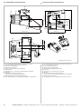
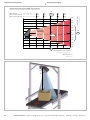
13 Geräteaufbau und Abmessungen
Abb. 11: Geräteaufbau und Abmessungen derSpiegelhaube Panorama
1. Vormontierte Befestigungsschrauben für den Lector
2. Lector, nicht im Lieferumfang
3. Messpunkt für Leseabstand
4. Kerbe zum mittigen Ausrichten zur Sichtfeldbreite
5. Optische Achse
6. Skew-Winkel von 10°, konstruktiv durch die Spiegelhaube vorgegeben
7. Typenschild
8. Spiegel mit Schutzfolie und Hinweisschild
Schutzfolie erst vor der Inbetriebnahme abziehen
9. Befestigungsbohrungen für die Spiegelhaube (4 Stück)
ß Pfeil „conveying direction“ zur Ausrichtung der Spiegelhaube zum Förderband
97.28
(3.83)
84.11
(3.31)
186.91
(7.39)
353.8
(13.93)
243.8
(9.60)
124
(4.88)
200
(7.87)
111
(4.37)
106
(4.17)
118.15
(4.65)
38.1
(1.50)
40
(1.57)
6.4
(0.25)
∅ 6.4
10°
12
45
6
9
ß
M 1:5
7
8
8
3
All dimensions in mm (inch)
6.4
(0.25)
13 Device structure and dimensions
Fig. 11: Device structure and dimensions of the Panorama mirror hood
1. Pre-mounted xing screws for Lector
2. Lector, not included with delivery
3. Measuring point for working distance
4. Notch for centrally aligning eld of view width
5. Optical axis
6. Skew angle of 10°, determined by the mirror hood
7. Type label
8. Mirrors with protective lm and information label
Do not remove protective lm until immediately before commissioning
9. Fixing holes for mirror hood (4x)
ß ‘Conveying direction’ arrow for aligning the mirror hood with the belt

8017697/2014-10-17 • Subject to change without notice • Irrtümer und Änderungen vorbehalten • © SICK AG • Germany • www.sick.com 11
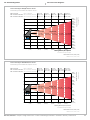
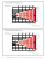
14 Sichtfelddiagramme 14 Field of view diagrams
181
(7.13)
...
Working distance/focus position
170 x 39
(6.69 x 1.54)
304 x 65
(11.97 x 2.56)
437 x 91
(17.20 x 3.58)
570 x 118
(22.44 x 4.65)
703 x 143
(27.68 x 5.63)
Field of view Sichtfeld LECTOR
®
642
35
(1.38)
0.11
(*4.2)
0.14 (*5.7)
77
(3.03)
0.25
(*9.9)
0.34 (*13.2)
91
(3.58)
0.33
(*12.8)
0.43 (*17.1)
105
(4.13)
0.40
(*15.6)
0.53 (*20.8)
59
(2.32)
0.18
(*7.1)
0.24 (*9.4)
Field of view width
400
(15.75)
700
(27.56)
1,000
(39.37)
1,300
(51.18)
1,600
(74.80)
0
100
(3.94)
100
(3.94)
200
(7.87)
200
(7.87)
300
(11.81)
300
(11.81)
400
(15.75)
400
(15.75)
500
(19.69)
500
(19.69)
Working distance/focus position
Dimensions in mm (inch/*mil)
Max. code size
Min. resolution 1D-Code
Min. resolution 2D-Code
Max. Codegröße
Min. Auflösung 1D-Code
Min. Auflösung 2D-Code
Arbeitsabstand/Fokuslage
Sichtfeldbreite
Maße in mm (inch/*mil)
Field of view diagram LECTOR
®
642, lens 35 mm
Sichtfelddiagramm LECTOR
®
642, Objektiv 35 mm
181
(7.13)
... 600
(23.62)
900
(35.43)
1,200
(47.24)
1,500
(59.06)
1,800
(70.87)
Working distance/focus position
172 x 38
(6.77 x 1.50)
261 x 56
(10.28 x 2.20)
349 x 74
(13.74 x 2.91)
438 x 93
(17.24 x 3.66)
527 x 111
(20.75 x 4.37)
Field of view Sichtfeld LECTOR
®
642
35
(1.38)
0.11 (*4.2)
0.14
(*5.5)
70
(2.76)
0.21 (*8.1)
0.27
(*10.8)
85
(3.35)
0.26 (*10.1)
0.34
(*13.5)
100
(3.94)
0.30 (*12.0)
0.41
(*16.0)
55
(2.17)
0.15 (*6.1)
0.21
(*8.1)
Field of view width
0
100
(3.94)
100
(3.94)
200
(7.87)
200
(7.87)
300
(11.81)
300
(11.81)
400
(15.75)
400
(15.75)
Dimensions in mm (inch/*mil)
Max. code size
Min. resolution 1D-Code
Min. resolution 2D-Code
Max. Codegröße
Min. Auflösung 1D-Code
Min. Auflösung 2D-Code
Arbeitsabstand/Fokuslage
Sichtfeldbreite
Maße in mm (inch/*mil)
Field of view diagram LECTOR
®
642, lens 50 mm
Sichtfelddiagramm LECTOR
®
642, Objektiv 50 mm

12 8017697/2014-10-17 • Subject to change without notice • Irrtümer und Änderungen vorbehalten • © SICK AG • Germany • www.sick.com
181
(7.13)
... 400
(15.75)
600
(23.62)
800
(31.50)
1,000
(39.37)
1,200
(47.24)
Field of view Sichtfeld LECTOR
®
654
313 x 58
(12.32 x 2.28)
474 x 83
(18.66 x 3.27)
634 x 109
(24.96 x 4.29)
795 x 134
(31.30 x 5.28)
313 x 107
(12.32 x 4.21)
474 x 154
(18.66 x 6.06)
634 x 201
(24.96 x 7.91)
795 x 248
(31.30 x 9.76)
955 x 159
(37.60 x 6.26)
955 x 295
(37.60 x 11.61)
Field of view Sichtfeld LECTOR
®
652
58
(2.28)
0.16 (*6.2)
0.21 (*8.2)
108 (4.25)
0.29 (*11.6)
0.39 (*15.4)
121 (4.76)
0.36 (*14.3)
0.48 (*19.1)
134 (5.28)
0.43 (*17.0)
0.58 (*22.7)
83 (3.27)
0.23 (*8.9)
0.30 (*11.8)
Max. code size
Min. resolution 1D-Code
Min. resolution 2D-Code
Field of view width
0
100
(3.94)
100
(3.94)
200
(7.87)
200
(7.87)
300
(11.81)
300
(11.81)
400
(15.75)
400
(15.75)
500
(19.69)
500
(19.69)
600
(23.62)
600
(23.62)
Max. Codegröße
Min. Auflösung 1D-Code
Min. Auflösung 2D-Code
Sichtfeldbreite
Working distance/focus position
Dimensions in mm (inch/*mil)
Arbeitsabstand/Fokuslage
Maße in mm (inch/*mil)
Field of view diagram LECTOR
®
652 and LECTOR
®
654, lens 25 mm
Sichtfelddiagramm LECTOR
®
652 und LECTOR
®
654, Objektiv 25mm
181
(7.13)
... 400
(15.75)
700
(27.56)
1,000
(39.37)
1,300
(51.18)
1,600
(74.80)
Working distance/focus position
Field of view Sichtfeld LECTOR
®
654
203 x 39
(7.99 x 1.54)
358 x 66
(14.09 x 2.60)
513 x 92
(20.20 x 3.62)
668 x 118
(26.30 x 4.65)
203 x 73
(7.99 x 2.87)
358 x 122
(14.09 x 4.80)
513 x 171
(20.20 x 6.73)
668 x 220
(26.30 x 8.66)
823 x 144
(32.40 x 5.67)
823 x 269
(23.40 x 10.59)
Field of view Sichtfeld LECTOR
®
652
39
(1.54)
0.11
(*4.2)
0.14
(*5.6)
92 (3.62)
0.25
(*9.9)
0.33
(*13.2)
118 (4.65)
0.32
(*12.7)
0.43
(*16.9)
144 (5.67)
0.39
(*15.5)
0.53
(*20.7)
66 (2.60)
0.18
(*7.0)
0.24
(*9.4)
Field of view width
0
100
(3.94)
100
(3.94)
200
(7.87)
200
(7.87)
300
(11.81)
300
(11.81)
400
(15.75)
400
(15.75)
500
(19.69)
500
(19.69)
Dimensions in mm (inch/*mil)
Max. code size
Min. resolution 1D-Code
Min. resolution 2D-Code
Max. Codegröße
Min. Auflösung 1D-Code
Min. Auflösung 2D-Code
Arbeitsabstand/Fokuslage
Sichtfeldbreite
Maße in mm (inch/*mil)
Field of view diagram LECTOR
®
652 and LECTOR
®
654, lens 35 mm
Sichtfelddiagramm LECTOR
®
652 und LECTOR
®
654, Objektiv 35 mm

8017697/2014-10-17 • Subject to change without notice • Irrtümer und Änderungen vorbehalten • © SICK AG • Germany • www.sick.com 13
Working distance/focus position
600
(23.62)
900
(35.43)
1,200
(47.24)
1,500
(59.06)
1,800
(70.87)
Field of view width
181
(7.13)
...
72 (2.83)
0.11 (*4.1)
0.14 (*5.5)
133 (5.24)
0.20 (*8.1)
0.27 (*10.8)
162 (6.38)
0.25 (*10.0)
0.34 (*13.4)
190 (7.48)
0.30 (*12.0)
0.41 (*16.0)
105 (4.13)
0.16 (*6.1)
0.21 (*8.2)
0
100
(3.94)
100
(3.94)
200
(7.87)
200
(7.87)
300
(11.81)
300
(11.81)
400
(15.75)
400
(15.75)
Field of view Sichtfeld LECTOR
®
654
203 x 38
(7.99 x 1.50)
307 x 56
(12.09 x 2.20)
411 x 75
(16.18 x 2.95)
515 x 93
(20.28 x 3.66)
203 x 72
(7.99 x 2.83)
307 x 106
(12.09 x 4.17)
411 x 140
(16.18 x 5.51)
515 x 174
(20.28 x 6.85)
618 x 111
(24.33 x 4.37)
618 x 208
(24.33 x 8.19)
Field of view Sichtfeld LECTOR
®
652
Dimensions in mm (inch/*mil)
Max. code size
Min. resolution 1D-Code
Min. resolution 2D-Code
Max. Codegröße
Min. Auflösung 1D-Code
Min. Auflösung 2D-Code
Arbeitsabstand/Fokuslage
Maße in mm (inch/*mil)
Field of view diagram LECTOR
®
652 and LECTOR
®
654, lens 50 mm
Sichtfelddiagramm LECTOR
®
652 und LECTOR
®
654, Objektiv 50 mm
Sichtfeldbreite
181
(7.13)
... 1,800
(70.87)
600
(23.62)
900
(35.43)
1,200
(47.24)
1,500
(59.06)
Working distance/focus position
Field of view Sichtfeld LECTOR
®
654
192 x 35
(7.56 x 1.38)
291 x 52
(11.46 x 2.05)
389 x 69
(15.31 x 2.72)
488 x 86
(19.21 x 3.39)
192 x 66
(7.56 x 2.60)
291 x 98
(11.46 x 3.86)
389 x 129
(15.31 x 5.08)
488 x 161
(19.21 x 6.34)
587 x 102
(23.11 x 4.02)
587 x 192
(23.11 x 7.56)
Field of view Sichtfeld LECTOR
®
652
35
(1.38)
0.10 (*3.8)
0.13 (*5.1)
68 (2.68)
0.19 (*7.4)
0.25 (*9.9)
85 (3.35)
0.24 (*9.3)
0.31 (*12.4)
102 (4.02)
0.28 (*11.1)
0.37 (*14.8)
52 (2.05)
0.14 (*5.7)
0.19 (*7.5)
Field of view width
0
100
(3.94)
100
(3.94)
200
(7.87)
200
(7.87)
300
(11.81)
300
(11.81)
400
(15.75)
400
(15.75)
Dimensions in mm (inch/*mil)
Max. code size
Min. resolution 1D-Code
Min. resolution 2D-Code
Max. Codegröße
Min. Auflösung 1D-Code
Min. Auflösung 2D-Code
Arbeitsabstand/Fokuslage
Sichtfeldbreite
Maße in mm (inch/*mil)
Field of view diagram LECTOR
®
652 and LECTOR
®
654, lens 54 mm
Sichtfelddiagramm LECTOR
®
652 und LECTOR
®
654, Objektiv 54 mm

14 8017697/2014-10-17 • Subject to change without notice • Irrtümer und Änderungen vorbehalten • © SICK AG • Germany • www.sick.com
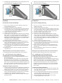
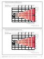
Interpretation des Diagramms Interpreting the diagram
181 ... 400 600 1,000 1,200
Field of view Sichtfeld
LECTOR
®
654
313 x 107 474 x 154 795 x 248 955 x 295
58
0.16
0.21
121
0.36
0.48
134
0.43
0.58
83
0.23
0.30
Max. code size
Min. resolution 1D-Code
Min. resolution 2D-Code
Field of view width
0
100
100
200
200
300
300
400
400
500
500
600
600
Max. Codegröße
Min. Auflösung 1D-Code
Min. Auflösung 2D-Code
Sichtfeldbreite
Working distance/focus position
Dimensions in mm
Arbeitsabstand/Fokuslage
Maße in mm
Example: Field of view diagram LECTOR
®
654, lens 25 mm
Beispiel: Sichtfelddiagramm LECTOR
®
654, Objektiv 25mm
108
0.29
0.39
634 x 201
800
1
2
4
3
634
5
4
10°

8017697/2014-10-17 • Subject to change without notice • Irrtümer und Änderungen vorbehalten • © SICK AG • Germany • www.sick.com 15
Mit Hilfe des Diagramms können Sie folgende Daten bestimmen:
■ Abmessungen des Sichtfeldes für die gewählte Codeauösung
■ Maximalen Leseabstand für die gewählte Codeauösung
Beispiel:
Gegeben 1:
■ Variante Lector
®
: Lector
®
654 mit 25 mm Objektiv
■ Code: 1D-Code
■ Geforderte Auösung: 0,29 mm
■ Max. Codegröße: 108 mm
Die maximale Codegröße darf die in dem Sichtfelddiagramm
angegebene maximale Codegröße nicht überschreiten.
Abgelesen
■ Sichtfeld 2: 634 mm x 201 mm
■ Sichtfeldbreite 3: 634 mm
■ Sichtfeldlänge 2: 201 mm
■ Leseabstand 4: 800 mm
Montageabstand berechnen
Den Montageabstand berechnen Sie mit untenstehender Formel.
Der Skew-Winkel von 10° ist durch die Spiegelhaube fest vorge-
ben.
Formel:
Montageabstand = Leseabstand * cos 10°
Montageabstand = 800 mm * cos 10° = 689,86 mm =>
ca. 690 mm
You can use the diagram to determine the following data:
■ Dimensions of the eld of view for the selected code resolution
■ Maximum working distance for the selected code resolution
Example:
Given 1:
■ Lector
®
variant: Lector
®
654 with 25 mm lens
■ Code: 1D-Code
■ Required resolution: 0.29 mm
■ Maximum code size: 108 mm
The maximum code size may not exceed the maximum code
size stated in the eld of view diagram.
Read
■ Field of view 2: 634 mm x 201 mm
■ Field of view width 3: 634 mm
■ Field of view length 2: 201 mm
■ Working distance 4: 800 mm
Calculating mounting distance
You can calculate the mounting distance using the formula below.
The skew angle of 10° is xed, and is determined by the mirror
hood.
Formula:
Mounting distance = working distance * cos 10°
Mounting distance = 800 mm * cos 10° = 689.86 mm =>
approx. 690 mm
Seite wird geladen ...
-
 1
1
-
 2
2
-
 3
3
-
 4
4
-
 5
5
-
 6
6
-
 7
7
-
 8
8
-
 9
9
-
 10
10
-
 11
11
-
 12
12
-
 13
13
-
 14
14
-
 15
15
-
 16
16


SICK Panorama mirror hood for Lector ® 64x/65x Mounting instructions
- Typ
- Mounting instructions
in anderen Sprachen
Verwandte Artikel
-
SICK LMS111-10100S09 Bedienungsanleitung
-
-
-
-
-
-
-
-
Andere Dokumente
-
 CombiSteel 7178.0310 Benutzerhandbuch
-
Zeiss Victory Harpia Bedienungsanleitung
-
Celestron 22203 Benutzerhandbuch
-
Ground Zero GZIF 40X Bedienungsanleitung
-
Danfoss AME 655/658 SU/658 SD/659 SD Bedienungsanleitung
-
Manfrotto MALAJ050M-3LBB Datenblatt
-
-
