SICK External Ring Illuminations for Image-based SICK Code Readers Mounting instructions
- Typ
- Mounting instructions

MONTAGEANLEITUNG
FITTING INSTRUCTIONS
Externe Ringbeleuchtungen
External Ring Illuminations
Für kamera-basierte SICK Codeleser
For Image-based SICK Code Readers

2 # 20 8011337/UM38/2011-02
SICK AG · Germany · All rights reserved · Subject to change without notice · Irrtümer und Änderungen vorbehalten
Inhalt
1. Produkteigenschaften .................................................................. 2
2. Bestimmungsgemäße Verwendung ............................................ 2
3. Zu Ihrer Sicherheit........................................................................ 3
4. Wartung ........................................................................................ 6
5. Lieferumgang (bei Bestellung eines Sets) .................................. 6
6. Voraussetzungen zur Installation und Inbetriebnahme ............ 6
7. Montage ........................................................................................ 7
8. Elektrischer Anschluss ................................................................. 8
9. Triggerung der Ringbeleuchtung ................................................. 8
10. Fehlersuche ................................................................................ 14
11. Technische Daten ....................................................................... 14
12. Bestellinformationen .................................................................. 16
13. Maßbilder .................................................................................... 16
13.1 Maßbilder Ringbeleuchtungen ............................................... 16
13.2 Maßbild ICR84x-2Bx020 mit Ringbeleuchtung..................... 17
13.3 Maßbild ICR84x-2Ax0x0 mit Ringbeleuchtung ..................... 18
13.4 Maßbild ICR84x-2L FlexLens mit Ringbeleuchtung .............. 19
13.5 Maßbild Montageplatte Nr. 2050691 (Zubehör) .................. 20
Contents
1. Features ........................................................................................ 2
2. Intended use................................................................................. 2
3. Safety information ........................................................................ 3
4. Maintenance ................................................................................. 6
5. Scope of delivery (only applicable to sets) ................................. 6
6. Installation and Commissioning Requirements ......................... 6
7. Installation .................................................................................... 7
8. Electrical Installation.................................................................... 8
9. Triggering the external illumination ............................................. 8
10. Troubleshooting .......................................................................... 14
11. Technical Data ............................................................................ 14
12. Ordering Information .................................................................. 16
13. Dimensional drawings ............................................................... 16
13.1 Dimensional drawings ring illumination units ....................... 16
13.2 Dim. drawing ICR84x-2Bx020 with ring illumination ............ 17
13.3 Dim. drawing ICR84x-2Ax0x0 with ring illumination ............. 18
13.4 Dim. drawing ICR84x-2L FlexLens with ring illumination ..... 19
13.5 Dim. drawing mounting plate no. 2050691 (accessory) ..... 20
Artikel-Nr.*)/Typ Beleuch- Licht- Unterstützte
tungsfeld farbe Codeleser
2034076 Dunkelfeld Rot ICR84x-2Bx0x0
(Fokuslage 80 mm)
2040503 Dunkelfeld Rot ICR84x-2Ax0x0
(Fokuslage 50 mm)
1048371/ICL170-F222 Hellfeld Rot ICR84x-2L FlexLens
1052495/ICL260-F222
1052472/ICL280-F222
1046820/ICL300-F222
1047957/ICL300-F202S01 Hellfeld Infrarot ICR845-2L0020S01
*) Ringbeleuchtungen unter anderen Artikelnummern auch als Sets
(Beleuchtung, Montagematerial und Anschlussleitung) erhältlich.
■ LED-Risikogruppe RG 0
■ Triggerung (Einschaltzeitpunkt/Blitzdauer) durch den Codeleser
■ Montage mit zwei Befestigungswinkeln direkt am Codeleser
■ Versorgungsspannung DC 24 V ± 20 % extern, Anschluss über
Anschlussmodul CDB620, CDB420 oder CDM420
■ Elektrischer Anschluss über 4-pol. M8-Stecker am Gehäuse
■ Schutzart IP 65
■ Wartungsfrei
■ Die Ringbeleuchtungen ICL170-/ICL260-/ICL280-/ICL300-F222
und ICL300-F202S01 sind UL60950-zertifiziert bei Versorgung
durch ein LPS- oder Class-2-Netzgerät (siehe auch Angaben zur
UL-Zertifizierung, Seite 15)
■ Optionales Zubehör:
- Geschirmte Anschlussleitung 2 m (im Set enthalten), 5 m, 10 m
- Montageplatte zur Stabilisierung
EG-Konformitätserklärung:
Siehe Produktseiten im Internet (www.sick.com)
2. Bestimmungsgemäße Verwendung
Die Dunkelfeld- und Hellfeld-Beleuchtungen sind für den Einsatz in
der industriellen Bildverarbeitung bestimmt.
Part no.*)/Type Illumina- Light Supported
tion field color Code Readers
2034076 Dark field Red ICR84x-2Bx0x0
(Focus pos. 80 mm)
2040503 Dark field Red ICR84x-2Ax0x0
(Focus pos. 50 mm)
1048371/ICL170-F222 Bright field Red ICR84x-2L FlexLens
1052495/ICL260-F222
1052472/ICL280-F222
1046820/ICL300-F222
1047957/ICL300-F202S01 Bright field Infrared ICR845-2L0020S01
*) By using other order numbers, the ring illumination units are also
available as several sets (ring illumination, mounting material, cable).
■ LED risk group RG 0
■ Triggered by the code reader (switching on/off, flash duration)
■ Directly mounted on the code reader using 2 brackets
■ External 24 V DC ± 20 % power supply, connected via CDB620,
CDB420 or CDM420 connection modules
■ 4-pin M8 plug-in connection on the housing
■ Enclosure rating IP 65
■ Maintenance-free
■ The ring illumination units ICL170-/ICL260-/ICL280-/ICL300-
F222 and ICL300-F202S01 are certified according to UL60950
when LPS power units or Class 2 power units are used (see also
Details for UL certification, Page 15)
■ Optional accessory:
- Shielded cable 2 m (6.56 ft) (included in the set), 5 m (16.4 ft)
or 10 m (32.8 ft)
- Mounting plate for stabilization
EC Conformity Declaration:
See product pages in the Internet (www.sick.com)
2. Intended use
The dark field and bright field illumination units are designed for
use in industrial image processing.
1. Produkteigenschaften der Ringbeleuchtungen
■ Leistungsstarke, externe Ringbeleuchtungen für kamera-basierte
Codeleser ICR84x-2X:
1. Features of the ring illuminations units
■ Powerful, external ring illumination units for ICR84x-2X image-
based code readers:

8011337/UM38/2011-02
3 # 20
© SICK AG · Germany · All rights reserved · Subject to change without notice · Irrtümer und Änderungen vorbehalten
LED-Strahlung!
Die Ringbeleuchtungen (Typen siehe Seite 2) arbei-
ten mit LEDs der Risikogruppe RG 0 (freie Gruppe,
kein Risiko) nach IEC/EN 62471.
Die zugängliche Strahlung der LEDs ist unter vernünftigerweise vor-
hersehbaren Bedingungen und bestimmungsgemäßer Verwendung
für das menschliche Auge und die menschliche Haut ungefährlich.
Vorübergehende, irritierende optische Wirkungen (z.B. Blendung,
Blitzblindheit, Nachbilder, Beeinträchtigungen des Farbsehens) kön-
nen, insbesondere bei niedriger Umfeldhelligkeit nicht gänzlich
ausgeschlossen werden. Schutzvorkehrungen sind nicht erforder-
lich. Die gesamte Fläche der durchsichtigen, ringförmigen Kunst-
stoffscheibe ist Austrittsöffnung der LED-Strahlung.
Vorsicht — bestimmungsfremder Einsatz kann zu gefährlicher Strah-
lungsexposition führen.
Nicht längere Zeit absichtlich direkt in die Beleuchtung schauen.
Gehäuse der Beleuchtung nicht öffnen. (Die Öffnung unterbricht
nicht die Einschaltung der LEDs durch den Codeleser.)
Gültige Bestimmungen zur photobiologischen Sicherheit von
Lampen und Lampensystemen in ihrer neuesten Fassung
beachten.
Strahlungsleistung
Die LEDs der Beleuchtungen arbeiten mit einer Peak-Wellenlänge
von = 620 nm (sichtbares Rotlicht) bzw. 850 nm (Infrarotlicht bei
Typ ICL300-F202S01).
Die mittleren Strahldichten liegen für das spezifizierte Tastverhält-
nis (siehe 11. Technische Daten, Seite 14 ff) unterhalb der Grenz-
werte für die Risikogruppe RG 0 des aussendenden Wellenlängen-
bereichs gemäß IEC 62471 (2006-07) bzw. EN 62471 (2008-09):
■ Photochemische Netzhautschädigung, L
B
<100 W/(m
2
sr) inner-
halb 2,8 Stunden
■ Thermische Netzhautschädigung, L
R
<280 kW/(m
2
sr) innerhalb
10 Sekunden (Rotlicht)
■ Thermische Netzhautschädigung, L
IR
<60 kW/(m
2
sr) innerhalb
1.000 Sekunden (Infrarotlicht)
■ Infrarot-Bestrahlung, E
IR
<100W/m innerhalb 1.000 Sekunden
Wichtig:
Es ist keine Wartung erforderlich, um die Einhaltung der Grenzwer-
te der Risikogruppe RG 0 zu gewährleisten.
ACHTUNG:
Die Überschreitung des spezifizierten Tastverhältnisses kann zu ei-
ner Überschreitung der Grenzwerte der Risikogruppe RG 0 führen.
LED radiation!
The ring illumination units (for types see Page 2)
operate with LEDs of the risk group RG 0 (exempt
group, no risk) according to IEC/EN 62471.
Regarding the intended use, under normal and sensible conditions,
the accessible radiation of the LEDs is not hazardous to the human
eye and skin. Temporary optical irritations like e.g. blinding,
blindness due to flashes, afterimages, impairment ability to see
colors, however cannot be excluded particularly with regards to low
ambient light intensity. No safety measures are required.
The entire area of the transparent, ring-shaped plastic window acts
as a LED outlet aperture.
Caution — use of controls, adjustments or performance of pro-
cedures other than those specified herein may result in hazardous
radiation exposure.
Never look directly into the illumination on purpose for long time.
Do not open the illumination housing. (Opening the housing
does not deactivate the LEDs by the Code Reader.)
Always observe the latest valid version of optical radiation
protection regulations for photobiological safety of lamps and
lamp system.
Radiation power
The LEDs of the illumination units operate at a peak wavelength of
= 620 nm (visible red light) respectively 850 nm (infrared light for
type ICL300-F202S01).
The average radiances for the specified duty cycle (see 11. Techni-
cal Data, Page 14 and 15) are lower than the radiance limits of the
risk group RG 0 for the emitted wavelength range according to IEC
62471 (2006-07) respectively EN 62471 (2008-09):
■ Photochemical damage of retina, L
B
<100 W/(m
2
sr) within
2.8 hours
■ Thermical damage of retina, L
R
<280 kW/(m
2
sr) within
10 seconds (red light)
■ Thermical damage of retina, L
IR
<60 kW/(m
2
sr) within
1,000 seconds (infrared light)
■ Infrared irradiation, E
IR
<100W/m within 1,000 seconds
Important:
Maintenance is not required to ensure compliance with LED risk
group RG 0.
ATTENTION:
Exceeding the specified duty cycle can exceed the risk group RG 0
limits.
CAUTION
3. Zu Ihrer Sicherheit
■ Vor der Inbetriebnahme diese Montageanleitung lesen.
■ Anschluss, Montage, Einstellung nur durch Fachpersonal.
■ Ringförmige Kunststoffscheibe des Lichtaustritts vor Verunreini-
gung und Beschädigung schützen.
3.1 LED-Strahlung
■ Beleuchtung so anbringen, dass keine unangenehme Arbeitsbe-
dingungen entstehen.
■ Personen mit Dispositionen zur photosensitiven Epilepsie sollen
nicht direkt in das sichtbare Beleuchtungsfeld schauen und sich
mehr als 1 m entfernt aufhalten, falls die Beleuchtung im
Blitzbetrieb mit 4 bis 30 Hz betrieben wird.
3. Safety information
■ Read the fitting instructions before starting operation.
■ Connection, assembly, and settings only by competent staff.
■ Protect ring-shaped plastic window of light outlet against soiling
and damages.
3.1 LED radiation
■ Install the light in such a way that no unpleasant working
conditions are created.
■ Persons with dispositions to photosensitive epilepsy should not
look directly into the visible illuminated area and keep a distance
more than 1 m (3.28 ft) if the illumination is operated in flash
mode with 4 to 30 Hz.
VORSICHT

4 # 20 8011337/UM38/2011-02
SICK AG · Germany · All rights reserved · Subject to change without notice · Irrtümer und Änderungen vorbehalten
■ Vorgehensweise zur Kontrolle des Tastverhältnisses, das sich
durch die Konfiguration des Codelesers ergibt, siehe Seite 9.
3.2 Elektrische Sicherheit: Gefahr durch Ausgleichsströme
bei unterschiedlichen Erdpotentialen
3.2.1 Änderung der Norm 60950-1
Die Norm 60950-1 (2006-04) wurde mit der Änderung A11 (2009-
03) erweitert. Die Änderung ist ab 01-12-2010 verbindlich.
Die Ringbeleuchtungen ICL170-/ICL260-/ICL280-/ICL300-F222
und ICL300-F202S01 sind auf elektrische Sicherheit gemäß dieser
geänderten Norm ausgelegt und geprüft.
3.2.2 Voraussetzungen für den sicheren Betrieb der obiger Ring-
beleuchtungen zusammen mit den Codelesern
Die externe Ringbeleuchtung wird über ein Anschlussmodul
CDB620/CDM420 mit einer geschirmten Leitung mit dem Code-
leser verbunden (Abb. 1). Dieser wiederum ist an weitere Peri-
pheriegeräte (Lesetakt-Sensor(en), Stromversorgung, SPS, Host
etc.) angeschlossen. Der Leitungsschirm z.B. der Anschlussleitung
für die Ringbeleuchtung liegt dabei am Metallgehäuse der Beleuch-
tung sowie an der Klemmenleiste „Shield“ des Anschlussmoduls
auf. Über das Modul bietet sich die Erdung der Kombination aus
Ringbeleuchtung/Codeleser/Anschlussmodul an.
Falls die Peripheriegeräte ebenfalls Metallgehäuse besitzen und der
Leitungsschirm ebenfalls an deren Gehäuse aufliegt, wird davon
ausgegangen, dass alle beteiligten Geräte in der Installation das
gleiche Erdpotential haben. Dies erfolgt z.B. durch die Montage der
Geräte auf leitende Metallflächen, die fachgerechte Erdung der
Geräte/Metallflächen in der Anlage und falls erforderlich, einen nie-
derimpedanten und stromtragfähigen Potentialausgleich zwischen
Bereichen mit unterschiedlichen Erdpotentialen.
Sind diese Bedingungen nicht erfüllt, z.B. bei Geräten innerhalb
eines weit verteilten Systems über mehrere Gebäude, können
Potentialausgleichströme über die Leitungsschirme zwischen den
Geräten aufgrund unterschiedlicher Erdpotentiale fließen.
■ For procedure to check the resulted duty cycle based on the
configuration of the code readers see page 9.
3.2 Electrical safety: Risk of equalizing currents at different
ground potential
3.2.1 Change to standard 60950-1
Standard 60950-1 (2006-04) has been added to with the change
A11 (2009-03). As of December 1, 2010, the change is obligatory.
The ring illumination units ICL170-/ICL260-/ICL280-/ICL300-F222
and ICL300-F202S01 have been designed and checked according
to the changed standard.
3.2.2 Conditions for the safe operation of the above listed
illumination units in combination with the code readers
The external ring illumination unit is connected to the coder reader
via a CDB620/CDM420 connection module by using a shielded
cable (Fig. 1). The code reader itself is connected to further
peripheral devices (clock reading pulse sensor(s), power supply,
PLC, host etc.). The shield of the cable of the illumination unit for
instance, lies on its metal housing and on the terminal shield of the
connection module. The grounding of the combination of ring
illumination unit, code reader and connection module can be
performed via the module.
If the peripheral devices also have metal housing and if the cable
shield also lies on their housing, it is assumed that all devices
involved in installation have the same ground potential. This is
achieved for instance by mounting the devices on conductive metal
surfaces, correctly grounding the devices/metal surfaces in the
system and if necessary via a low-impedance and stable current
carrying equipotential bonding between areas with different ground
potentials.
If these conditions are not met, e.g. on devices in a widely distrib-
uted system over several buildings, potential equalization currents
may, due to different ground potentials, flow along the cable shields
between the devices.
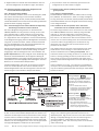
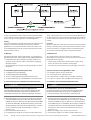
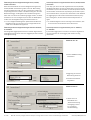
Abb. 1: Ströme in den Leitungsschirmen durch Erdpotentialunterschiede/Fig. 1: Currents in the cable shields due to differences in ground potential
Zu Abb. 1: Durch unterschiedliche Erdpotentiale von Geräten inner-
halb eines verteilten Systems können hohe Ströme in den Leitungs-
schirmen auftreten und diese schädigen oder zerstören. Aufgrund
des unzureichenden Erdpotentailausgleichs entstehen Spannungs-
differenzen zw. den Erdungspunkten 1 und 2. Über die geschirmten
Leitungen/Metallgehäuse schließt sich die Stromschleife.
To fig. 1. Due to different ground potentials of the devices in a
distributed system, high currents can occur in the cable shields and
damage or irreparably damage them. Due to insufficient ground
potential equalization, voltage differences arise between the
grounding points 1 and 2. The current loop closes via the shielded
cables and housing.
Varning och åtjärder
Utrustning som är kopplad till skyddsjord
via jordat vägguttag och/eller via annan
utrustning och samtidigt är kopplad till
kabel-TV nät kan i vissa fall medfora risk
for brand.
For att undvika detta skall vid
anslutning av utrustningen till kabel-TV
nät galvanisk isolator finnas mellan
utrustningen och kabel-TV nätet.
Advarsel og tiltaker
Utstyr som er koplet til beskyttelsesjord
via nettplugg og/eller via annet jord-
tilkoplet utstyr - og er tilkoplet et kabel-TV
nett, kan forårsake brannfare.
For å unngå dette skal det ved
tilkopling av utstyret til kabel-TV nettet
installeres en galvanisk isolator
mellom utstyret og kabel-TV nettet.

8011337/UM38/2011-02
5 # 20
© SICK AG · Germany · All rights reserved · Subject to change without notice · Irrtümer und Änderungen vorbehalten
3.2.3 Abhilfemaßnahmen
Die vorrangige Lösung für das Vermeiden von Potentialausgleichs-
strömen auf den Leitungsschirmen ist die Sicherstellung eines
niederimpedanten und stromtragfähigen Potentialausgleichs. Ist
dieser nicht realisierbar, dienen die folgenden beiden Lösungsan-
sätze als Vorschlag.
Wichtig:
Es wird davon abgeraten, die Leitungsschirme aufzutrennen. Mit
dieser Maßnahme kann die Einhaltung der EMV-Grenzwerte und
der sichere Betrieb der Datenschnittstellen der Geräte nicht mehr
gewährleistet werden.
a) Maßnahmen bei räumlich weit verteilten Systeminstallationen
Bei räumlich weit verteilten Systeminstallationen, mit entsprechend
großen Potentialunterschieden, wird der Aufbau lokaler Inseln und
die Verbindung dieser Inseln über kommerziell erhältliche elektro-
optische Signaltrenner empfohlen. Mit dieser Maßnahme wird ein
Höchstmaß an Robustheit gegenüber elektromagnetischen Störun-
gen erreicht, bei gleichzeitiger Einhaltung sämtlicher Anforderungen
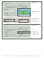
der EN 60950-1. Fig. 2 zeigt die Wirkungsweise dieser Maßnahme.
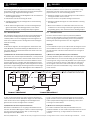
Zu Abb. 2: Durch den Einsatz der elektro-optischen Signaltrenner
zwischen den Inseln wird die Erdschleife aufgetrennt. Innerhalb der
Inseln werden durch einen tragfähigen Potentialausgleich Aus-
gleichsströme auf den Leitungsschirmen verhindert.
b) Maßnahmen bei kleinen Systeminstallationen
Bei kleineren Installationen mit nur geringen Potentialunterschie-
den kann die isolierte Montage der Codeleser und der Peripheriege-
räte eine hinreichende Lösung sein. Abb. 3, Seite 6 zeigt die
Wirkungsweise dieser Maßnahme.
Abb. 2: Maßnahme: Einsatz elektro-optischer Signaltrenner/Fig. 2: Use of electro-optical signal converters
Verletzungs-/Beschädigungsgefahr durch elektrischen Strom!
Potentialausgleichsströme zwischen der Kombination aus Ring-
beleuchtung/Codeleser/Anschlussmodul und/oder den Peripherie-
geräten können ggf. folgende Auswirkungen haben:
■ Gefährliche Spannungen am Metallgehäuse z.B. des Codelesers
und der Ringbeleuchtung
■ Fehlverhalten oder die Zerstörung der Geräte
■ Schädigung/Zerstörung des Leitungsschirms durch Erhitzung
sowie Kabelbrände
Wo die örtlichen Gegebenheiten ein sicheres Erdungskonzept
(gleiches Potential in allen Erdungspunkten) nicht erfüllen,
Maßnahmen gemäß dem nachfolgenden Kapitel ergreifen.
GEFAHR DANGER
Risk of injury/risk of damage via electrical current!
Potential equalization currents between the combination of ring
illumination unit/code reader/connection module and/or the
peripheral devices can have the following effects:
■ Dangerous voltages on the metal housing of the code reader or
the ring illumination unit for instance
■ Incorrect function or irreparable damage to the devices
■ Damage/irreparable damage of the cable shield due to heating
and cable fires
Where local conditions are unfavorable and thus do not meet
conditions for a safe earthing method (same ground potential at
all grounding points), take measures from the following chapter.
6.2 Remedial measures
The most common solution to prevent potential equalization
currents on cable shields is to ensure low-impedance and stable
current carrying equipotential bonding. If this is not possible the
following two solution approaches serve as a suggestion.
Important:
It is not advisable to open up the cable shields. As doing this means
that the EMC limit values can no longer be complied with and that
the safe operation of the device data interfaces can no longer be
guaranteed.
a) Measures for widely distributed system installations
On widely distributed system installations with correspondingly large
potential differences, we recommend setting up local islands and
connecting them using commercially available electro-optical signal
converters. This measure achieves a high degree of resistance to
electromagnetic interference while at the same time complying
withall the requirements of EN 60950-1. Fig. 2 shows the function
of this measure.
To Fig. 2: the ground loop is opened by using the electro-optical
signal converters between the islands. Within the local islands, a
stable equipotential bonding prevents equalizing currents from
occurring at the cable shields.
b) Measures for small system installations
For smaller installations with small potential differences, the
insulated installation of code readers and peripheral devices can be
a sufficient solution. Fig. 3, Page 6 shows the function of this
measure.

6 # 20 8011337/UM38/2011-02
SICK AG · Germany · All rights reserved · Subject to change without notice · Irrtümer und Änderungen vorbehalten
To fig. 3: Ground loops are, even in the event of large differences in
the ground potential, effectively prevented. Meaning that equalizing
currents cannot occur anymore via the cable shield and the metal
housing.
Important:
The power supply of the SICK devices and the connected peripheral
devices must also guarantee the required level of insulation. Under
certain circumstances, a tangible potential can develop between
the insulated metal housings and the local ground potential.
4. Maintenance
The ring illumination units do not require any maintenance.
Depending on the operation area we recommended to carry out the
following measures regularly:
– Clean carefully the light outlet window (plastic) using a damp,
lint-free cloth and a mild, antistatic cleaning agent
– Check the screw connections and electrical plug-in connections.
5. Scope of delivery (only applicable to sets)
■ 1 x Ring illumination unit (type-dependent)
■ 2 x mounting brackets (type-dependent)
■ 8 x respectively 6 x hexagon socket screws M3, self-locking
■ 1 x cable, 2 m (6.56 ft), with 4-pin M8 socket and open end
6. Installation and Commissioning Requirements
Zu Abb. 3: Erdschleifen werden, selbst bei hohen Erdpotentialdiffe-
renzen wirksam verhindert. Dadurch sind fließen keine Ausgleichs-
ströme mehr über die Leitungsschirme und Metallgehäuse.
Wichtig:
Die Stromversorgung für die SICK Geräte sowie die angeschlossene
Peripherie müssen dann ebenfalls die erforderliche Isolation
gewährleisten. Unter Umständen kann zwischen den isoliert mon-
tierten Metallgehäusen und dem örtlichen Erdpotential ein berühr-
bares Potential entstehen.
4. Wartung
Die Ringbeleuchtungen arbeiten wartungsfrei. Je nach Einsatzum-
gebung empfehlen sich jedoch folgende, regelmäßige Maßnahmen:
– Kunststoffscheibe des Lichtaustritts vorsichtig mit Hilfe eines
fuselfreien Tuchs und einer milden, antistatischen Reinigungs-
flüssigkeit reinigen
– Verschraubungen und elektrische Steckverbindungen auf festen
Sitz prüfen
5. Lieferumfang (bei Bestellung eines Sets)
■ 1 x Ringbeleuchtung (typabhängig)
■ 2 x Befestigungswinkel (typabhängig)
■ 8 x bzw. 6 x Befestigungsschrauben M3, selbstsichernd
■ 1 x Anschlussleitung 2 m (4-pol. M8-Buchse und offenes Ende)
6. Voraussetzungen zur Installation und Inbetriebnahme
■ Betriebsanleitung je nach verwendetem Codelesertyp: Betriebs-
anleitung ICR840-2X (Artikel-Nr. 8012156), Betriebsanleitung
ICR845-2X (Artikel-Nr. 8012376) oder Betriebsanleitung ICR849-
2X (Artikel-Nr. 8014080). Alle Betriebsanleitungen sind auf der
CD-ROM „Manuals & Software 1D/2D Code Readers“ enthalten,
die dem Codeleser beiliegt oder downloadbar im Internet
(www.sick.com).
■ Innensechskant-Schlüssel, SW 2,5
■ Versorgungsspannung DC 24 V, erzeugt nach IEC 60364-4-41.
Mögliche Funkstörungen beim Einsatz in Wohngebieten!
Die Hellfeld-Beleuchtungen ICL170-/ICL260-/ICL280-/ICL300-
F222 und ICL300-F202S01 sind Produkte der EMV-Klasse A.
Diese Beleuchtungen nur in Industrieumgebungen einsetzen!
RF interferences in case of use in residential areas!
The bright field illumin. units ICL170-/ICL260-/ICL280-/ICL300-
F222 and ICL300-F202S01 are products of the EMC class A.
Use the illumination units exclusively in industrial areas!
■ Operating instructions depending on used code reader type:
operating instructions ICR840-2X (part no. 8012157), operating
instructions ICR845-2X (part no. 8012377) or operating instruc-
tions ICR849-2X (part no. 8014081). All instructions available on
the "Manuals & Software 1D/2D Code Readers" CD-ROM pro-
vided with the code reader or via download from the Internet
(www.sick.com).
■ Wrench for hexagon socket screws, wrench size 2,5
■ 24 V DC power supply in accordance with IEC 60364-4-41.
Abb. 3: Maßnahme: Isolierte Montage der Sensoren und der Peripheriegeräte/Fig. 3: Insulated assembly of the sensors and peripheral devices
NOTEHINWEIS

8011337/UM38/2011-02
7 # 20
© SICK AG · Germany · All rights reserved · Subject to change without notice · Irrtümer und Änderungen vorbehalten
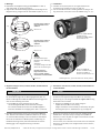
7. Montage
■ Platzbedarf der Ringbeleuchtung gemäß Maßbilder in Abb. 8,
Seite 16 bis Abb. 12, Seite 19 beachten.
■ Abgerundetes Ende des Befestigungswinkels für Montage an der
Ringbeleuchtung, eckiges Ende für den ICR84x-2 (Abb. 4 a , b, c).
Abb. 4: Montage der Befestigungswinkel an der Ringbeleuchtung/Fig. 4: Mounting the brackets on the ring illumination unit
Ringbeleuchtung Artikel-Nr.
Ring illumination unit no.
2034076
Einheit aus ICR84x-2B00x0
und Beleuchtung
Assembly of ICR84x-2B00x0
and illumination unit
M3 x 12 mm
M3 x 12 mm
M3 x 8 mm
ACHTUNG!
Für Gewindebohrungen
M5 Hinweis unter Abbildung
beachten.
ATTENTION!
For tapped through holes M5
please see note below figure.
a)
b)
c)
Einheit aus ICR84x-2L
FlexLens und Beleuchtung
Assembly of ICR84x-2L
FlexLens and illumination unit
(Abbildung ähnlich / picture can differ from actual product)
7. Installation
■ Consider the required space for the ring illumination unit
according to Fig. 8, Page 16 to Fig. 12, Page 19.
■ Use the rounded end of the mounting bracket for fitting on the
ring illumination, the square end for the ICR84x-2 (
Fig. 4 a, b, c).
■ Ringbeleuchtungen ICL170-/ICL260-/ICL280-/ICL300-F222 und
ICL300-F202S01:
■ Illumination units ICL170-/ICL260-/ICL280-/ICL300-F222 and
ICL300-F202S01:
Ringbeleuchtung Artikel-Nr.
Ring illumination unit no.
2040503
Ringbeleuchtungen/
Ring illumination units
ICL170-/ICL260-/ICL280-/
ICL300-F222, ICL300-F202S01
M5 x 11 mm
Beschädigungsgefahr des ICR84x-2L FlexLens!
Die Gewindebohrungen M5 der Befestigungswinkel (Abb. 4 c)
NICHT zur Montage des ICR84x-2L und der Beleuchtung gemein-
sam an einer Halterung verwenden.
Den ICR84x-2L an der Halterung stets mit Hilfe
der Sacklochgewinde M5 seines Gehäuses befestigen.
Für erhöhte Stabilität der Einheit steht die Montageplatte
Artikel-Nr. 2050691 zur Verfügung (siehe Abb. 13, Seite 20)
1. Beide Befestigungswinkel einzeln am Lesefenster (ICR84x-2A
oder -2B) bzw. am Lichteintritt (ICR84x-2L FlexLens) so montie-
ren, dass die Winkel bündig mit den Gerätekanten abschließen.
Hierzu für die Schrauben im Winkel jeweils eine Bohrung mit
Rundlochvertiefung und im passenden Abstand eine weitere
Bohrung (ggf. in der Langlochvertiefung) verwenden.
NOTEHINWEIS
1. Mount the two brackets on either side of the reading window
(ICR84x-2A or -2B) respectively on the light inlet (ICR84x-2L
FlexLens) in such a way that the edges of the brackets are flush
with the edges of the device.
For the screws, use a drill with round recess and in the adequate
distance a second drill (in the elongated hole recess if existent)
in the bracket.
Risk of damage to the ICR84x-2L FlexLens!
Do NOT use the tapped through holes M5 in the mounting
brackets (Fig. 4 c) for fitting the ICR84x-2L together with the ring
illumination unit to a holder.
Always fit the ICR84x-2L to the holder using the
tapped blind holes M5 on its housing.
A higher steadiness of the assembly is achieved by using the
mounting plate part no. 2050691 (see Fig. 13, Page 20)

8 # 20 8011337/UM38/2011-02
SICK AG · Germany · All rights reserved · Subject to change without notice · Irrtümer und Änderungen vorbehalten
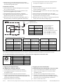
Pin- und Aderfarbbelegung der Anschlussleitung / Pin and wire color assignment of connection cable
Abb. 5: ICR84x-2: Anschluss der Ringbeleuchtung am Schaltausgang „Result 1“, direkt am ICR84x-2 oder über Anschlussmodule
Fig. 5: ICR84x-2: Connecting the ring illumination unit to the “Result 1“ switching output, directly on the ICR84x-2 or via the connection modules
Ringbeleuchtung
Ring illumination unit
CDB420 Ringbeleuchtung
Ring illumination
Klemme Signal Aderfarbe Pin
Terminal Signal Wire color Pin
19 U
IN
* braun/brown 1
16 Result 1 weiß/white 2
13 GND blau/blue 3
5 Shield shield
ICR84x-2 Ringbeleuchtung
Ring illumination
Pin Signal Aderfarbe Pin
Wire color Pin
1V
S
braun/brown 1
12 Result 1 weiß/white 2
5 GND blau/blue 3
Über Anschlussmodule/via connection modules:
Pin-/Aderfarbbelegung für
Anschlussleitungen:
Artikel-Nr. 6030681 (2 m)
Artikel-Nr. 6030682 (5 m)
Artikel-Nr. 6030683 (10 m)
Pin/wire color assignment for cables:
part no. 6030681 (2 m (6.56 ft))
part no. 6030682 (5 m (16.4 ft))
part no. 6030683 (10 m (32.8 ft))
2. Ringbeleuchtung an die Befestigungswinkel anschrauben.
Die Ausrichtung des Anschlussteckers kann hierbei nach einer
der beiden Seiten gewählt werden.
8. Elektrischer Anschluss
■ Sicherheitshinweise zu Erdpotentialausgleichsströmen gemäß
Kap. 3.2, Seite 4 beachten!
■ Die Ringbeleuchtung gemeinsam mit dem Codeleser an die
gleiche Versorgungsspannung anschließen.
1. Versorgungsspannung für den Codeleser ausschalten.
2. Dose (Buchse) der Anschlussleitung auf den M8-Stecker der
Ringbeleuchtung aufstecken und festschrauben.
3. Mit den Adern des freien Endes den Schaltausgang „Result 1“
(low-side-Schalter) des Codelesers gemäß Abb. 5 beschalten.
2. Screw the ring illumination unit onto the mounting brackets.
The plug can be aligned on one of the two sides.
8. Electrical installation
■ Observe the safety notes for ground potential equalization
currents in Chapter 3.2, Page 4.
■ Connect the ring illumination to the same power supply voltage
as the code reader.
1. Switch off the power supply voltage for the code reader.
2. Attach the socket of the connection cable to the M8 plug of the
ring illumination unit and tight the socket.
3. Wiring the open end to the “Result 1“ switching output (low side
switch) of the code reader according to Fig. 5.
CDB620 Ringbeleuchtung
Ring illumination
Klemme Signal Aderfarbe Pin
Terminal Signal Wire color Pin
14 U
IN
* braun/brown 1
20 Result 1 weiß/white 2
22 GND blau/blue 3
5 Shield shield
CDM420-0001 Ringbeleuchtung
Ring illumination
Klemme Signal Aderfarbe Pin
Terminal Signal Wire color Pin
29 +24V* braun/brown 1
14 Result 1 weiß/white 2
16 GND blau/blue 3
5 Shield shield
9. Triggerung der Ringbeleuchtung
9.1 Triggerung im Codeleser aktivieren
1. PC über Ethernet mit ICR84x-2 elektrisch verbinden.
2. Versorgungsspannung für Anschlussmodul einschalten.
Der ICR84x-2 startet.
3. Konfigurationssoftware CLV-Setup auf dem PC starten.
4. Über den Verbindungsassistenten die Kommunikation mit dem
ICR84x-2 aufnehmen wie in der Betriebsanleitung ICR84x-2 des
betreffenden Codelesers beschrieben.
5. Registerkarte K
AMERAEINSTELLUNGEN wählen.
9. Triggering the external illumination
9.1 Activating the external illumination in the code reader
1. Connect electrically the PC to ICR84x-2 via the Ethernet.
2. Switch on the power supply for the connection module.
The ICR84x-2 starts.
3. Start the CLV-Setup configuration software on the PC.
4. Establish the communication with the ICR84x-2 using the
connection assistant as described in the ICR84x-2 operating
instructions of the corresponding Image Code Reader.
5. Select the C
AMERA SETTINGS tab.
Pin Aderfarbe/wire color Signal
1 braun/brown DC 24 V ± 20 %
2 weiß/white Trigger
3 blau/blue GND
4 schwarz/black n.c.
– Metallgeflecht/metal braiding Schirm/Shield
Ansicht von vorne
front view

8011337/UM38/2011-02
9 # 20
© SICK AG · Germany · All rights reserved · Subject to change without notice · Irrtümer und Änderungen vorbehalten
Artikel-Nr./Typ Zulässiges Tastverhältnis
2034076 Max. 1:5 (ein/aus) im Lesetakt
2040503
1048371/ ICL170-F222 Max. 1:10 (ein/aus) im Lesetakt,
1052495/ ICL260-F222 max. Impulsdauer 5 ms
1052472/ ICL280-F222
1046820/ ICL300-F222
1047957/ ICL300-F202S01
Für die Berechnung des aktuellen Tastverhältnisses, das sich aus
der Konfiguration ergibt, wie folgt vorgehen:
1. Registerkarte L
ESEKONFIGURATION (Abb. 4a, Seite 9) anzeigen.
2. Upload aus dem Gerät durchführen (Taste F3)
3. Die Werte für die Blitzdauer und die Bildwiederholrate ablesen.
4. Die Werte miteinander in den gleichen Potenzen multiplizieren.
Beispiel für
ICL300-F222:
Abgelesen: Blitzdauer 1.026 s, Bildwiederholrate 299,6 Hz
Berechnet: 0,001 s x 299,6 1/s = 0,29
0,29 > 0,1! Tastverhältnis zu groß!
Part no./type Permissible duty cycle
2034076 Maximum 1:5 (ON/OFF) during
2040503 reading clock
1048371/ ICL170-F222 Maximum 1:10 (ON/OFF) during
1052495/ ICL260-F222 reading clock
1052472/ ICL280-F222 Maxium pulse duration 5 ms
1046820/ ICL300-F222
1047957/ ICL300-F202S01
Perform the following procedure for calculating the current duty
cycle based on the configuration:
1. Display the D
EVICE CONFIGURATION tab (Fig. 4b, Page 10).
2. Perform an upload from the device (F3 key)
3. Note the flash pulse (1 s = 0.000001 s) and the frame rate.
4. Multiply the flash pulse by the frame rate.
Example for
ICL300-F222:
Read: Flash pulse 1,026 s, frame rate 299.6 Hz
Calculated: 0.001 s x 299.6 1/s = 0.29
0.29 > 0.1! The duty cycle is too high!
ICR84x-2A oder -2B:
6. In der Sektion I
NTERNER BELEUCHTUNGSMODUS die Option „alle LEDs
aus“ wählen (Abb. 6a, Seite 10).
7. Zur Registerkarte G
ERÄTEKONFIGURATION wechseln.
8. Schaltfläche S
CHALTAUSGANGS-PARAMETER anklicken.
9. In der Sektion A
USGABEFUNKTIONEN für Ausgang 1 die Option „Exter-
ner Blitz“ wählen (Abb. 6a, Seite 10).
10. In der Sektion E
XTERNER BLITZ die Option „Blitzimpulse“ als Trig-
gerart sowie das Verhalten wählen.
ICR84x-2L FlexLens:
6. In der Sektion E
XTERNE BELEUCHTUNG die Option „Externe Beleuch-
tung an Ausgang 1“ aktivieren (Abb. 6a, Seite 10).
Alle ICR84x-2:
1. Neue Konfiguration zum ICR84x-2 übertragen (
temp. Download).
2. Nach Test der Lesequalität mit Hilfe der Funktion I
MAGEFTP
(siehe Betriebsanleitung ICR84x-2) abschließend die neue
Konfiguration per Download zum ICR84x-2 übertragen (perma-
nente Speicherung).
9.1 Kontrolle des Tastverhältnisses
Ein zu großes Tastverhältnis der externen Beleuchtung im Lesetakt
kann zur Überschreitung der Grenzwerte der Risikogruppe RG 0
führen. Das Tastverhältnis berechnet sich aus Blitzdauer mal
Bildwiederholrate des Codelesers.
Bei der Parametrierung des ICR84x-2 auf die Einhaltung des
zulässigen Tastverhältnisses achten.
Die folgenden, gemeinsam vorgenommen Einstellungen beeinflus-
sen das zulässige Tastverhältnis (siehe auch Abb. 7a, Seite 12):
■ niedrige Objektgeschwindigkeit (shutter)
■ Auswahl „Geringe Auflösung“
■ Einschränkung des Bildbereichs
Zulässige Tastverhältnisse:
ICR84x-2A or -2B:
6. In the I
NTERNAL ILLUMINATION MODE section, select the “all LEDs off“
option (Fig. 6b, Page 11).
7. Change to the D
EVICE CONFIGURATION tab.
8. Click the R
ESULT OUTPUT PARAMETERS button.
9. In the R
ESULT FUNCTIONS section, select the “External flash pulse“
option for output 1 (Fig. 6b, Page 11).
10. In the E
XTERNAL FLASH section, select “Flash pulse“ for triggering
source and select the behavior.
ICR84x-2L FlexLens:
6. In the E
XTERNAL ILLUMINATION MODE section, select “Active external
Illumination on output 1“ (Fig. 6b, Page 11).
All ICR84x-2:
1. Transfer the new configuration to ICR84x-2 (temp. download).
2. Once the reading quality has been tested with the ImageFTP
function (see ICR84x-2 Operating Instructions) transfer the new
configuration to the ICR84x-2 via download (save permanently).
9.1 Checking the duty cycle
If the duty cycle of the external illumination is too high per reading
clock, the radiation limits of risk group RG 0 can be exceeded. For
calculating the duty cycle multiply the flash pulse by the frame rate
of the code reader.
When configuring the ICR84x-2 ensure to comply with the
permissible duty cycle.
The following, combined settings affect the permissible duty cycle
(see also Fig. 7b, Page 13):
■ low object velocity (shutter)
■ Option "Low resolution"
■ Limiting the Image Geometry
Permissible duty cycles:

10 # 20 8011337/UM38/2011-02
SICK AG · Germany · All rights reserved · Subject to change without notice · Irrtümer und Änderungen vorbehalten
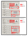
Abb. 6a: CLV-Setup: Ausschalten der integrierten Beleuchtung (ICR84x-2A oder -2B) und Aktivierung der Triggerung der ext. Ringbeleuchtung
1.Interne LED-Beleuchtung
ausschalten.
2.Triggerung der externen
Beleuchtung aktivieren.
3. Verhalten der Beleuch-
tung wählen.
ICR84x-2A oder -2B
ICR84x-2L FlexLens
Haken setzen im
Kontrollkästchen
„Externe Beleuchtung
an Ausgang 1 aktivie-
ren“ (entspricht
Grundeinstellung).
Überlastungsschutz für Ringbeleuchtungen ICL170/ICL260/
ICL280 und ICL300
Wenn das Tastverhältnis der externen Ringbeleuchtung ICL170/
ICL260/ICL280 und ICL300 zu groß ist, kann die Beleuchtung
thermisch überlastet werden. Um dies zu verhindern, schaltet ein
temperaturgesteuerter Schalter in der Beleuchtung den normalen
Betriebsmodus ggf. vorübergehend aus. Die Beleuchtung kann
dann nicht mehr durch den Codeleser getriggert werden, sie blinkt
stattdessen mit einer niedrigen Frequenz. Nach der Abkühlphase
schaltet sich die Ringbeleuchtung automatisch wieder ein.
Um eine mögliche Blendung durch plötzliches Einschalten der
Ringbeleuchtung zu vermeiden, auch im ausgeschalteten Zu-
stand nicht in die Beleuchtung blicken.
Überlastungsschutz für Ringbeleuchtungen Artikel-Nr. 2034076/
Nr. 2040503
Ein anliegender Triggerimpuls wird nach 1 Sekunde abgeschnitten,
die Ringbeleuchtung erlischt. Ein neuer Triggerimpuls startet wieder
die Ringbeleuchtung.
Overload protection for ring illuminations ICL170/ICL260/ICL280
and ICL300
If the duty cycle of the external ring illumination ICL170/ICL260/
ICL280 and ICL300 is too high, the illumination can be thermically
overloaded. To prevent the overload, the normal operation mode of
the illumination is switched off temporarily by an internal tempera-
ture-controlled switch, if required. The illumination is then disabled
for triggering by the code reader and flashes with low frequency.
After cooling down, the illumination automatically switches on
again.
To avoid blinding due to short switching on of illumination, also
do not look into the illumination when switched off.
Overload protection for ring illuminations part no. 2034076/
no. 2040503
A permanent trigger pulse is cut after 1 second, the ring illumina-
tion then switches off. A new trigger pulse restarts the ring
illumination.

8011337/UM38/2011-02
11 # 20
© SICK AG · Germany · All rights reserved · Subject to change without notice · Irrtümer und Änderungen vorbehalten
Fig. 6b: CLV-Setup: Switching off the integrated illumination (ICR84x-2A or -2B) and activating the trigger for the external ring illumination unit
1.Switch off the integrated
LED illumination.
2.Enable the triggering of
the external illumination
unit
3.Select the mode of the
external illumination unit
ICR84x-2A or -2B
ICR84x-2L FlexLens
Activate the check box
"Activate external
illumination on output 1"
(as done in the default
setting)

12 # 20 8011337/UM38/2011-02
SICK AG · Germany · All rights reserved · Subject to change without notice · Irrtümer und Änderungen vorbehalten
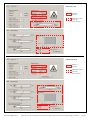
Abb. 7a: CLV-Setup: Werte zur Berechnung des Tastverhältnisses für externe Beleuchtung sowie die das Tastverhältnis beeinflussenden Parameterwerte
ICR84x-2A oder -2B
ICR84x-2L FlexLens
Abzulesende
Werte
Einzustellende/
zu kontrollierende
Parameterwerte
Abzulesende
Werte
Einzustellende/
zu kontrollierende
Parameterwerte

8011337/UM38/2011-02
13 # 20
© SICK AG · Germany · All rights reserved · Subject to change without notice · Irrtümer und Änderungen vorbehalten
Fig. 7b: CLV-Setup: Values for calculating the duty cycle of the external illumination and the parameter values affecting the duty cycle
ICR84x-2A or -2B
ICR84x-2L FlexLens
Values to
be read
Parameter values
to be set/
to be checked
Values to
be read
Parameter values
to be set/
to be checked

14 # 20 8011337/UM38/2011-02
SICK AG · Germany · All rights reserved · Subject to change without notice · Irrtümer und Änderungen vorbehalten
10. Fehlersuche
Störung
Nach Anlegen der Versorgungs-
spannung am CDB620/CDB420/
CDM420 leuchtet die LED „De-
vice Ready“ des ICR84x-2 nicht
Die Ringbeleuchtung mit sicht-
barem Rotlicht erzeugt keine rote
Blitzbeleuchtung
Schlechte Bildqualität im
ICR84x-2 durch falsche Blitzdauer
(Anzeige über ImageFTP)
Abhilfe
CDB620/CDB420/CDM420:
Schalter S 1 (Power) in Position
„ON“ bringen
Lesung für den ICR84x-2 takten
Verdrahtung der Ringbeleuchtung
kontrollieren
ICR84x-2A und -2B:
Mit Hilfe von CLV-Setup die Aus-
gabefunktion des Schaltausgangs
„Result 1“ auf „Externer Blitz“
einstellen (Abb. 6a, S. 10).
ICR84x-2L FlexLens:
Mit Hilfe von CLV-Setup die
Option „Externe Beleuchtung an
Ausgang 1 aktivieren“ wählen.
Download (permanent) zum
ICR84x-2!
ICR84x-2A und -2B:
Interne LED-Beleuchtung aus-
schalten
Mit Hilfe von CLV-Setup die Dauer
des Blitzimpulses variieren bis
Bildqualität zufriedenstellend ist.
Download (permanent) zum
ICR84x-2!
Wichtig: Fehlersuche in Zusammenhang mit den Anschlussmodu-
len CDB620/CDB420/CDM420 siehe deren Betriebsan-
leitungen.
10. Troubleshooting
Malfunction
"Device Ready" LED of the
ICR84x-2 does not light up when
power supply is connected to the
CDB620/CDB420/CDM420
The ring illumination unit using
visible red light does not generate
red flash pulses
Poor image quality in the
ICR84x-2 due to wrong flash
pulse duration
(when displayed in ImageFTP)
Important: For troubleshooting of the CDB620/CDB420/
CDM420 connection modules see the respective
operating instructions.
Remedy
CDB620/CDB420/CDM420:
set switch S 1 (Power) to "ON"
Start the trigger for ICR84x-2
Check the wiring of the ring
illumination unit
ICR84x-2A and -2B:
Using CLV-Setup, set the result
function for the "Result 1"
switching output to “External
flash pulse" (Fig. 6b, page 11).
ICR84x-2L FlexLens:
Using CLV-Setup, select the
"Activate external illumination on
output 1" option.
Download (permanent option) to
the ICR84x-2.
ICR84x-2A and -2B:
Switch off the internal LED
illumination
Using CLV-Setup, modify the flash
pulse duration until the image
quality becomes sufficient for
decoding.
Download to the ICR84x-2.
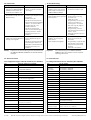
Typ Artikel-Nr. 2034076/ Nr. 2040503
Beleuchtungsart Dunkelfeld
Unterstützte Codeleser Nr. 2034076: ICR84x-2B
Nr. 2040503: ICR84x-2A
Beleuchtungsquelle 36 x LED
Wellenlänge Rotlicht ( = 615 nm ± 15 nm)
Zuläss. Tastverhältnis Max. 1:5 (ein/aus) pro Lesetakt
MTTF 50.000 h (bei worst-case-Tastverhältnis
1/5 (ein/aus) pro Triggerzyklus)
LED-Risikogruppe Klasse RG 0 nach EN 62471 (2008-09)
Triggereingang Ein: > DC 8 V, aus: < DC 4 V, max. 30 V
Elektrischer Anschluss 4-pol. M8-Stecker
Versorgungsspannung DC 24 V ± 20 % nach IEC 60364-4-41 (2005)
Leistungsaufnahme Max. 15 W
Gehäuse / Lichtaustritt Metall / Kunststoff
Gehäusedurchmesser 99 mm, siehe auch Abb. 5, Seite 13
Farbe Schwarz
Schutzart IP 65 nach EN 60529 (1991) +A1 (2000)
Schutzklasse III
nach EN 61010-1 (2001-03)
EMV-Prüfung Nach EN 61000-6-2 (2005-08),
EN 61000-4-6 (1996-07)
Gewicht Ca. 250 g (ohne Anschlussleitung)
Temperatur (Betr./Lager) 0 ... +50 °C/–20 ... +70 °C
Rel. Luftfeuchtigkeit Max. 95 %, nicht kondensierend
Befestigung 4 x Gewindebohrung M3
11. Technische Daten
11.1 Ringbeleuchtungen Artikel-Nr. 2034076/Nr. 2040503
11. Technical Data
11.1 Ring illumination Part No. 2034076/No. 2040503
Type Part No. 203407
Illumination mode Dark field
Supported No. 2034076: ICR84x-2B
code readers No. 2040503: ICR84x-2A
Illumination source 36 x LEDs
Wavelength Red light ( = 615 nm ± 15 nm)
Permitted duty cycle Max. 1:5 (on/off) per reading cycle
MTTF 50,000 h (at worst case duty cycle 1/5 on/off)
LED risk group RG 0, accord. to EN 62471 (2008-09)
Trigger input ON: > 8 V DC, OFF: < 4 V DC, max. 30 V
Electrical connection 4-pin M8 plug
Power supply 24 V DC ± 20 % to IEC 60364-4-41 (2005)
Power consumption Max. 15 W
Housing / light outlet Metal / plastic
Housing diameter 99 mm (3.9 in), see Fig. 5, Page 13
Color Black
Enclosure rating IP 65, accord. to EN 60529 (1991) +A1 (2000)
Protection class III, accord. to EN 61010-1 (2001-03)
EMC-tested According to EN 61000-6-2 (2005-08),
EN 61000-4-6 (1996-07)
Weight Approx. 250 g (8.82 oz.), without cable
Temperature 0 to +50 °C/–20 to +70 °C
(operation/storage) (+32 to +122 °F/–4 to +158 °F)
Rel. air humidity Max. 95 %, non-condensing
Mounting 4 x tapped blind holes M3

8011337/UM38/2011-02
15 # 20
© SICK AG · Germany · All rights reserved · Subject to change without notice · Irrtümer und Änderungen vorbehalten
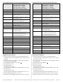
Type ICL170-F222 (part no. 1048371)
ICL260-F222 (part no. 1052495)
ICL280-F222 (part no. 1052472)
ICL300-F222 (part no. 1046820)
ICL300-F202S01 (part no. 1047957)
Illumination mode Bright field
Supported code readers ICR84x-2L FlexLens
Illumination 8 x LEDs
Wavelength ICL170-/ICL260-/ICL280-/ICL300-F222:
red light ( = 620 nm)
ICL300-F202S01: Infrared light ( = 850 nm)
Permitted duty cycle Max. 1:10 (on/off) per reading cycle,
max. pulse duration 5 ms
MTTF 50,000 h (at worst case duty cycle 1/10 on/off)
LED risk group RG 0, accord. to EN 62471 (2008-09)
Illumination field Diameter depends on type and distance,
see Fig. 9, Page 16
Trigger input ON: 1.5 V DC, OFF: 3.5 V DC, max. 28.8 V
Electrical connection 4-pin M8 plug on the housing
Power supply 24 V DC ± 20 % SELV or PELV according to
IEC 60364-4-41 (2005),
transient surge <1,500 V peak
Power consumption ICL170-F222:
Max. 1.4 W (max. pulse current 500 mA)
ICL260-/ICL280-/ICL300-F222, -F202S01:
Max. 5.1 W (max. pulse current 1.7 A)
Housing / light outlet Metal / plastic
Housing diameter 107 mm (4.21 in), see also Fig. 9, Page 16
Color Black
Electrical safety Accord. to EN 60950-1 (2006)/A11 (2009-03)
Protection class III, accord. to EN 61140 (2002) + A1 (2006)
Enclosure rating IP 65, accord. to EN 60529 (1991) +A1 (2000)
EMC-tested According to EN 61000-6-2 (2005-08),
EN 61000-6-4 (2007-01)
Weight Approx. 240 g (8.46 oz.), without cable
Temperature 0 to +40 °C/–20 to +70 °C
(operation/storage) (+32 to +104 °F/–4 to +158 °F)
Rel. air humidity Max. 90 %, non-condensing
Mounting Tapped blind holes: 4 x M3, 2 x M4
Typ ICL170-F222 (Artikel-Nr. 1048371)
ICL260-F222 (Artikel-Nr. 1052495)
ICL280-F222 (Artikel-Nr. 1052472)
ICL300-F222 (Artikel-Nr. 1046820)
ICL300-F202S01 (Artikel-Nr. 1047957)
Beleuchtungsart Hellfeld
Unterstützte Codeleser ICR84x-2L FlexLens
Beleuchtungsquelle 8 x LED
Wellenlänge ICL170-/ICL260-/ICL280-/ICL300-F222:
Rotlicht ( = 620 nm)
ICL300-F202S01: Infrarotlicht ( = 850 nm)
Zuläss. Tastverhältnis Max. 1:10 (ein/aus) pro Lesetakt,
max. Impulsdauer 5 ms
MTTF 50.000 h (bei worst-case-Tastverhältnis
1/10 (ein/aus) pro Triggerzyklus)
LED-Risikogruppe Klasse RG 0 nach EN 62471 (2008-09)
Beleuchtungsfeld Typen- und abstandsabhängiger Durchmesser
siehe Abb. 9, Seite 16
Triggereingang Ein: DC 1,5 V, Aus: DC 3,5 V, max. 28,8 V
Elektrischer Anschluss 4-pol. M8-Stecker am Gehäuse
Versorgungsspannung DC 24 V ± 20 % SELV oder PELV nach
IEC 60364-4-41 (2005),
transiente Überspannung < 1.500 V Peak
Leistungsaufnahme ICL170-F222:
max. 1,4 W (max. Pulsstrom 500 mA)
ICL260-/ICL280-/ICL300-F222, -F202S01:
max. 5,1 W (max. Pulsstrom 1,7 A)
Gehäuse / Lichtaustritt Metall / Kunststoff
Gehäusedurchmesser 107 mm, siehe auch Abb. 9, Seite 16
Farbe Schwarz
Elektrische Sicherheit Nach EN 60950-1 (2006)/A11 (2009-03)
Schutzklasse III,
nach EN 61140 (2002) + A1 (2006)
Schutzart IP 65, nach EN 60529 (1991) +A1 (2000)
EMV-Prüfung Nach EN 61000-6-2 (2005-08),
EN 61000-6-4 (2007-01)
Gewicht Ca. 240 g (ohne Anschlussleitung)
Temperatur (Betr./Lager) 0 ... +40 °C/–20 ... +70 °C
Rel. Luftfeuchtigkeit Max. 90 %, nicht kondensierend
Befestigung Gewindebohrungen: 4 x M3, 2 x M4
11.2 Ringbeleuchtungen ICL170/ICL260/ICL280/ICL300 11.2 Ring illumination ICL170/ICL260/ICL280/ICL300
Angaben zur UL-Zertifzierung
■ ICL260-/ICL280-/ICL300-F222 sowie ICL300-F202S01 sind
UL60950-zertifiziert bei Versorgung durch ein LPS- oder Class-2-
Netzgerät
■ Die Zertifizierung ist nur gültig bei entsprechender Gerätekenn-
zeichnung auf dem Typenschild
■ Versorgungsspannung DC 19,2 ... 28,8 V ...
■ Tastverhältnis max. 1:10
■ Leistungsaufnahme:
ICL170-F222: max. 1,4 W
ICL260-/ICL280-/ICL300-F222, ICL300-F202S01: max. 5,1 W
■ Stromaufnahme:
ICL170-F222: max. 0,5 A
ICL260-/ICL280-/ICL300-F222, ICL300-F202S01: max. 1,7 A
■ Betriebsumgebungstemperatur 0 ... +50 °C
■ Schutzart IP 65 der Ringbeleuchtungen nicht durch UL geprüft
Details for UL certification
■ ICL260-/ICL280-/ICL300-F222 and ICL300-F202S01 are
certified according to UL60950 when LPS power units or Class 2
power units are used
■ The certification is only valid with corresponding product marking
on the type plate
■ Supply voltage 19.2 to 28.8 V DC ...
■ Duty cycle max. 1:10
■ Power consumption:
ICL170-F222: max. 1.4 W
ICL260-/ICL280-/ICL300-F222, ICL300-F202S01: max. 5.1 W
■ Current consumption:
ICL170-F222: max. 0.5 A
ICL260-/ICL280-/ICL300-F222, ICL300-F202S01: max. 1.7 A
■ Operating ambient temperature 0 to +50 °C (+32 to +122 °F)
■ Enclosure rating IP 65 of the illumination units not tested by UL

16 # 20 8011337/UM38/2011-02
SICK AG · Germany · All rights reserved · Subject to change without notice · Irrtümer und Änderungen vorbehalten
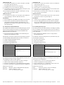
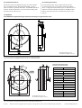
13. Maßbilder
13.1 Maßbilder Ringbeleuchtungen/dimensional drawing of ring illumination units
Alle Längenmaße in mm (in)
All measures of length in mm (in)
Abb. 8: Abmessungen der Ringbeleuchtungen Artikel-Nr. 2034076/2040503
Fig. 8: Dimensions of the ring illumination units part no. 2034076/2040503
Abb. 9: Abmessungen der Ringbeleuchtungen ICL170/ICL260/ICL280/ICL300
Fig. 9: Dimensions of the ring illumination units ICL170/ICL260/ICL280/ICL300
Abstand/Distance Durchmesser/Diameter
ICL170-F222
300 mm (11.82 in) 100 mm (3.94 in)
1.000 mm (39.4 in) 170 mm (6.7 in)
ICL260-F222
300 mm (11.82 in) 129 mm (5.1 in)
1.000 mm (39.4 in) 318 mm (12.5 in)
1.500 mm (59.1 in) 442 mm (17.4 in)
ICL280-F222
300 mm (11.82 in) 137 mm (5.4 in)
1.000 mm (39.4 in) 410 mm (16.15 in)
1.100 mm (43.34 in) 442 mm (17.4 in)
ICL300-F222/ICL300-F202S01
300 mm (11.82 in) 100 mm (3.94 in)
1.000 mm (39.4 in) 170 mm (6.7 in)
2.000 mm (78.8 in) 300 mm (11.82 in)
Abmessungen Beleuchtungsfeld
Dimensions of illumination field
Alle Längenmaße in mm (in)
All measures of length in mm (in)
12. Bestellinformationen
Bestellinformationen für Ringbeleuchtungen und deren Zubehör
siehe Produktinformation „Produktfamilie ICR800 – Kamera-
basierte Codeleser“ (Artikel-Nr. 8011333 , auf CD-ROM „Manuals &
Software 1D/2D Code Readers“, die dem Codeleser beiliegt oder
via Internet unter www.sick.com).
12. Ordering Information
For ordering information about ring illumination units and
accessories please refer to the product information "ICR800
Series – Image-based Code Readers" (part no. 8011334, on the
"Manuals & Software 1D/2D Code Readers" CD-ROM provided
with the code reader or from the website www.sick.com in the
internet).

8011337/UM38/2011-02
17 # 20
© SICK AG · Germany · All rights reserved · Subject to change without notice · Irrtümer und Änderungen vorbehalten
Gewinde/tapped
blind hole M5,
8 (0.31)
tief/deep (2x)
Gewinde/tapped
blind hole M5,
8 (0.31)
tief/deep (2x)
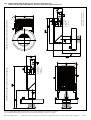
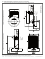
Abb. 10: ICR84x-2B00x0/-2B10x0: Abmessungen mit montierter Ringbeleuchtung Artikel-Nr. 2034076
Fig. 10: ICR84x-2B00x0/-B10x0: Dimensions with installed ring illumination unit part no. 2034076
13.2 Maßbild ICR84x-2B00x0/-2B10x0 mit montierter Ringbeleuchtung
Dimensional drawing ICR84x-2B00x0/-2B10x0 with installed ring illumination unit
Alle Längenmaße in mm (in)
All measures of length in mm (in)
ICR84x-2B00x0 (stirnseitiges Lesefenster/front end reading window): ICR84x-2B10x0 (seitliches Lesefenster/side reading window)

18 # 20 8011337/UM38/2011-02
SICK AG · Germany · All rights reserved · Subject to change without notice · Irrtümer und Änderungen vorbehalten
Gewinde/tapped
blind hole M5,
8 (0.31)
tief/deep (2x)
Gewinde/tapped
blind hole M5,
8 (0.31)
tief/deep (2x)
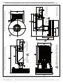
13.3 Maßbild ICR84x-2A00x0 und ICR84x-2A10x0 mit montierter Ringbeleuchtung
Dimensional drawing ICR84x-2A00x0 and ICR84x-2A10x0 with installed ring illumination unit
Abb. 11: ICR84x-2A00x0 und ICR84x-2A10x0: Abmessungen mit montierter Ringbeleuchtung Artikel-Nr. 2040503
Fig. 11: ICR84x-2A00x0 and ICR84x-2A10x0: Dimensions with installed ring illumination unit part no. 2040503
Alle Längenmaße in mm (in)
All measures of length in mm (in)
ICR84x--2A00x0 (stirnseitiges Lesefenster/front end reading window): ICR84x-2A10x0 (seitliches Lesefenster/side reading window)

8011337/UM38/2011-02
19 # 20
© SICK AG · Germany · All rights reserved · Subject to change without notice · Irrtümer und Änderungen vorbehalten
Abb. 12: ICR84x-2L00x0/-2L10x0 FlexLens: Abmessungen mit montierter Ringbeleuchtung ICL170, ICL260, ICL280 oder ICL300
Fig. 12: ICR84x-2L00x0/-2L00x0 FlexLens: Dimensions with installed ICL170, ICL260, ICL280 or ICL300 ring illumination unit
13.4 Maßbild ICR84x-2L00x0/-2L10x0 FlexLens mit montierter Ringbeleuchtung ICL170/ICL260/ICL280/ICL300
Dimensional drawing ICR84x-2L00x0/-2L10x0 FlexLens with installed ICL170/ICL260/ICL280/ICL300 ring illum. unit
Gewinde/tapped blind hole
M5, 8 (0.31) tief/deep (2x)
Alle Längenmaße in mm (in)
All measures of length in mm (in)
ICR845-2L00x0 (stirnseitiges Lesefenster)/(front end reading window):
ICR849-2L10x0 (seitliches Lesefenster/side reading window)
Gewinde/tapped blind hole
M5, 8 (0.31) tief/deep (2x)
ACHTUNG! Siehe Texthinweis in Kapitel 7. Montage, Seite 7.
ATTENTION! See information in Chapter 7. Installation, Page 7.
Gewindebohrung/
tapped through hole
M5, (2x)
Gewindebohrung/
tapped through hole
M5, (2x)

SICK AG · Waldkirch · Germany · www.sick.com
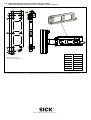
Abb. 13: Abmessungen der Montageplatte Artikel-Nr. 2050691 für Ringbeleuchtungen ICL170, ICL260, ICL280, ICL300 und ICR845-2L0020 FlexLens
Fig. 13: Dimensions of mounting plate part no. 2050691 for ICL170, ICL260, ICL280, ICL300 ring illumination units and ICR845-2L0020 FlexLens
13.4 Maßbild Montageplatte Artikel-Nr. 2050691 (optionales Zubehör)
Dimensional drawing mounting plate part no. 2050691 (optional accessory)
Alle Längenmaße in mm
All measures of length in mm
mm inch
0.5 0.02
2.95 0.12
5.1 0.20
5.5 0.21
5.9 0.23
8 0.31
10 0.39
mm inch
13.25 0.52
23.5 0.92
29 1.14
49.25 1.94
85.25 3.36
93 3.66
94.3 3.71
-
 1
1
-
 2
2
-
 3
3
-
 4
4
-
 5
5
-
 6
6
-
 7
7
-
 8
8
-
 9
9
-
 10
10
-
 11
11
-
 12
12
-
 13
13
-
 14
14
-
 15
15
-
 16
16
-
 17
17
-
 18
18
-
 19
19
-
 20
20


SICK External Ring Illuminations for Image-based SICK Code Readers Mounting instructions
- Typ
- Mounting instructions
in anderen Sprachen
Verwandte Artikel
-
SICK CDB620 Connection Module Bedienungsanleitung
-
-
-
-
-
-
-
-
-