Seite wird geladen ...

Universal Messumformer / transmitter CI 45 Seite / page 1
Bedienhinweis CI 45 9499 040 71441
Operation notes Version 8425 (05/2005)
Bedien-/operating version: 2
Deutsch English
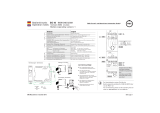
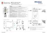
1Istwertanzeige Process value display
2Einheiten-Anzeige / erweiterte Bedienebene / Fehler-
liste / Werte aus Conf- und Para- Ebene
Display of units / extended operating level / error
list / values from Conf- and PArA- level
3Funktionsauswahl aktiv activated function processing
4Errorliste (2 x ô)
Fühlerfehler (FbF.x), Kurzschluss (Sht.x), Verpolung
(Pol.x), Grenzwertalarm (Lim.x)
Geräte-/Engineeringfehler (E.x)
Error list(2xô)
Sensor error (FbF.x), short circuit (Sht.x), polarity error
(Pol.x), limit value alarm (Lim.x)
Device / engineering failure (E.x)
5Inkrement-Taste / Schleppzeiger, Maximalwert Increment key / slave pointer for maximal value
6Enter-Taste / ruft erweiterte Bedienebene, bzw.
Errorliste auf
Enter key / calls up the extended operating
level, or error list
7Gerätezustand
grün: ok, Grenzwert 1 im Gutzustand
grün blinkend: kein Datenaustausch mit Buskoppler
rot: Grenzwert 1 aktiv
rot blinkend: Geräte- / Konfigurationsfehler
Device state
green lights: ok, limit value 1 is not active
green flashing: no data exchange with bus coupler
red lights: limit value 1 is active
red flashing: device error / configuration mismatch
8Anzeige-Element Display element
9Zustand des Schaltausgangs OUT1 / INP1 aktiv Status of switching outputs OUT1 / active INP1
10 Zustand des Schaltausgangs OUT2 / INP2 aktiv Status of switching outputs OUT2 / active INP2
11 Dekrement-Taste / Schleppzeiger, Minimalwert Decrement key / slave pointer for minimal value
13 PC-Anschluss für das Engineering Tool PC interface for the engineering tool
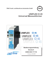
%
max.
95% rel.
max. 55°C
-10°Cmin.
22.5
(0,87”) 117.5 (4,63”)
99 (3,90”)
2.3
111 (4,37”)
5.5
(0,08”)
(0,20”)
click
Montage / mounting
Abmessungen / dimensions
Demontage / dismantling
1
Klemme /
terminal
5678
1234
15 16 17 18
11 12 13 14
Klemme /
terminal
UL certification:
Max. surrounding air temperature:
55°C
Only use 60/75°C copper conductors
To be used in a Pollution Degree 2
environment only
q
q
q
q
Use copper conductors only
INP1
OUT3
PWR
OUT1
OUT2
RS 485
Data A
Data A
Data B
Data B
RGND
RGND
top
16
15 17 18
System
INP2
di1
UL certification:
Output ratings:
max. 500 VA, 250V AC, 2A
(for resistive load)
q
V
14
13
12
16
15
11
mV
17 18
LN
~90-260V
~24V
8
76
3
2
1
5
34
(mV)
Logic
V
gZur Inbetriebnahme nutzen Sie bitte die Bedienungsanleitung
Bestellnr. 9499-040-71718 oder von der PMA - CD
For commissioning please use the operating manual
order no. 9499-040-71711 or from PMA CD

Universal Messumformer / transmitter CI 45 Seite / page 2
PArA
Funcµ
Name Value range Description Your value
tEmP 0...9999 Temperature of sensor for O2Measurement µ
t.I 0,1...9999 Integrator time [min] µ
P.I -9999...9999 Integrator offset µ
InP.1, InP.2
Name Value range Description
InL.1 (2) -1999...9999 Input value for the lower scaling point
OuL.1 (2) -1999...9999 Displayed value for the lower scaling point
InH.1 (2) -1999...9999 Input value for the upper scaling point
OuH.1 (2) -1999...9999 Displayed value for the lower scaling point
t.F1 (2) 0...999,9 Filter time constant [s]
b.F1 (2) 0...9999 Filter bandwidth
E.tc1 (2) OFF, 0...100 External temperature compensation [°C]
Cn.Frµ
Name Value range Beschreibung
Cnt.d 0,1...9999 Counter divider
Cnt.S 0...9999 Counter start value
Cnt.E 0...9999 Counter end value
Frq.L 0,000...100,0 lower input value [kHz]
Ou.L -1999...9999 lower output value [phys.]
Frq.H 0,000...100,0 upper input value [kHz]
Ou.H -1999...9999 Upper output value [phys.]
Frq.F 0,0...9999 filter time [s]
Lim
Name Value range Description
L.1 -1999...9999 Lower limit 1 (L.1< -1999 =off)
H.1 -1999...9999 Upper limit 1 (H.1< -1999 =off)
HYS.1 0...9999 Hysteresis limit 1
dEL.1 0...9999 Alarm delay from limit value 1
L.2 -1999...9999 Lower limit 2 (L.2< -1999 =off)
H.2 -1999...9999 Upper limit 2 (H.2< -1999 =off)
HYS.2 0...9999 Hysteresis limit 2
dEL.2 0...9999 Alarm delay from limit value 2
L.3 -1999...9999 Lower limit 3 (L.3< -1999 =off)
H.3 -1999...9999 Upper limit 3 (H.3< -1999 =off)
HYS.3 0...9999 Hysteresis limit 3
dEL.3 0...9999 Alarm delay from limit value 3
ConF
Func
Name Value
range Description
Fnc.1 Funktion 1 µ
1Process value = Inp1
2difference (Inp1 - Inp2)
3max. (Inp1, Inp2)
4min. (Inp1, Inp2)
5mean value (Inp1, Inp2)
6Switch-over (Inp1, Inp2)
7O2-function with constant probe temperature
8O2-function with measured probe temperature
9Counter / Frequency
10 Process value = Inp1 (TC from Inp2)
Fnc.2 Function 2
0no function
1Squarer
2Square root
Fnc.3 Funktion 3 µ
0no function
1tara-function
2sample & hold
3integrator
InP.1
Name Value
range Description
S.tYP Sensor type selection
0thermocouple type L (-100...900°C) , Fe-CuNi DIN
1thermocouple type J (-100...1200°C) , Fe-CuNi
2thermocouple type K (-100...1350°C), NiCr-Ni
Name Value
range Description
3thermocouple type N (-100...1300°C), Nicrosil-Nisil
4thermocouple type S (0...1760°C), PtRh-Pt10%
5thermocouple type R (0...1760°C), PtRh-Pt13%
6thermocouple type T (-200...400°C), Cu-CuNi
7thermocouple type C (0...2315°C), W5%Re-W26%Re
8thermocouple type D (0...2315°C), W3%Re-W25%Re
9thermocouple type E (-100...1000°C), NiCr-CuNi
10 thermocouple type B (0/100...1820°C), PtRh-Pt6%
18 special thermocouple (linearization necessary)
20 Pt100 (-200.0 ... 100,0 (150,0) °C)
21 Pt100 (-200.0 ... 850,0 °C)
22 Pt1000 (-200.0...850.0 °C)
23 special 0...4500 Ohm (preset to KTY11-6)
24 special 0...450 Ohm
25 special 0...1600 Ohm
26 special 0...160 Ohm
30 0...20mA / 4...20 mA
40 0...10V / 2...10 V ( Inp.1 only)
41 special (-2,5...115 mV)
42 special (-25...1150 mV)
43 special (-25...90 mV)
44 special (-500...500 mV)
45 special (-5...5 V) (Inp.1 only)
46 special (-10...10 V) (Inp.1 only)
47 special (-200..200 mV)
50 potentiometer 0...160 Ohm
51 potentiometer 0...450 Ohm
52 potentiometer 0...1600 Ohm
53 potentiometer 0...4500 Ohm
4wir Type of resistance connection (only for Inp.1)
03-wire-connection
14-wire-connection
S.Lin Linearization only adjustable at S.tYP:18, 23 ... 47
0none
1Linearization to specification. Creation of lineariza-
tion table with BlueControl (engineering tool) possi-
ble. The characteristic for KTY 11-6 temperature
sensors is preset.
Corr Measured value correction / scaling
0Without scaling
1Offset correction (at CAL level)
22-point correction (at CAL level)
3Scaling (at PArA level)
In.F OFF,
-1999...
9999
Alternative value for INPx
Cn.Frµ
Name Value
range Description
I.Fnc Function select
0Control input
1up counter, positive edge
2up counter, negative edge
3down counter, positive edge
4down counter, negative edge
5frequency measurement
Frq.t 0.1...20.0 Frequency-gate time [s]
Lim
Name Value
range Description
Fnc.1
(Fnc.2)
(Fnc.3)
Function of limit 1 (2, 3)
0switched off
1measured value monitoring
2Measured value monitoring + alarm status storage.
A stored limit value can be reset via error list or a digi-
tal input ( -> LOGI/Err.r)
3signal change in minutes
4signal change + alarm status storage. A stored limit va-
lue can be reset via error list or a digital input ( ->
LOGI/Err.r)
Src.1
(Src.2)
(Src.3)
Source of limit 1 (2, 3)
0process value = Absolute alarm
3measured value INP1
4measured value INP2
5Counter/frequency value
Out.1,Out.2µand Out3
Name Value range Description
O.tYP Signal type selection OUT3 only
0relay / logic
10 ... 20 mA continuous
24 ... 20 mA continuous
30...10 V continuous
42...10 V continuous
5transmitter supply
6frequency µ
O.Act Method of operation of output OUT1, 2 or 3
0direct / normally open
1inverse / normally closed
Name Value range Description
Lim.1 Limit 1 signal (only visible when O.TYP=0)
0not active
1active
Lim.2 Limit 2 signal (only visible when O.TYP=0)
0not active
1active
Lim.3 Limit 3 signal (only visible when O.TYP=0)
0not active
1active
Cnt Counter end signal µ
0not active
1active
FAi.1 INP1 error (only visible when O.TYP=0)
0not active
1active
FAi.2 INP2 error (only visible when O.TYP=0)µ
0not active
1active
FAi.F Frequency error signal µ
0not active
1active
Sb.Er System bus error signal µ
0not active
1active
Out.0 -1999
...9999 Scaling of the analog output for 0% (0/4mA or 0/2V,
only visible when O.TYP=1..5)
Out.1 -1999
...9999 Scaling of the analog output for 100% (20mA or 10V,
only visible when O.TYP=1..5)
Out.L -1999
...9999 Input value for lower output frequency µ
Frq.L 0...9999 lower output frequency [Hz] µ
Out.H -1999
...9999 Input value for upper output frequency µ
Frq.H 0...9999 upper output frequency [Hz] µ
O.Src Signal source of the analog output OUT3 (only visi-
ble when O.TYP=1..5)
0not active
3process value
7measured value INP1
8measured value INP2
10 Counter/frequency value µ
O.FAI Fail behaviour
0upscale
1downscale
LOGI
Name Value range Description
di.Fn Function of digital inputs (valid for all inputs)
0direct
1invers
2toggle key function (adjustable for 2-point-operation
with interface and di1)
L_r Local / Remote switching (Remote: adjusting of all
values by front keys is blocked)
0no function (switch-over via interface is possible)
1always active
2Di1 switches
7limit 1 switches
8limit 2 switches
9limit 3 switches
Err.r Reset of all error list entries
0no function (switch-over via interface is possible)
2Di1 switches
7limit 1 switches
8limit 2 switches
9limit 3 switches
I.ChG Switching between Inp1 and X2
0no function (switch-over via interface is possible)
1Di1 switches
7limit 1 switches
8limit 2 switches
9limit 3 switches
tArA Tare-function µ
0no function (switch-over via interface is possible)
2Di1 switches
7limit 1 switches
8limit 2 switches
9limit 3 switches
HOLd Sample & hold - function µ
0no function (switch-over via interface is possible)
2Di1 switches
7limit 1 switches
8limit 2 switches
9limit 3 switches
rES.L Reset minimum value
0no function (switch-over via interface is possible)
2Di1 switches
7limit 1 switches
8limit 2 switches
9limit 3 switches
Name Value range Description
rES.H Reset maximum value
0no function (switch-over via interface is possible)
2Di1 switches
7limit 1 switches
8limit 2 switches
9limit 3 switches
rES.I Reset integrator µ
0no function (switch-over via interface is possible)
2Di1 switches
6reset-keys switch
7limit 1 switches
8limit 2 switches
9limit 3 switches
rES.C Reset counter µ
0no function (switch-over via interface is possible)
6reset-keys switch
7limit 1 switches
8limit 2 switches
9limit 3 switches
othr
Name Value range Description
bAud Baudrate of the interface µ
02400 Baud
14800 Baud
29600 Baud
319200 Baud
438400 Baud
Addr 1...247 Address on the interace µ
PrtY Data parity on the interface µ
0no parity (2 stop bits)
1even parity
2odd parity
3no parity (1 stopbit)
S.IF System interface µ
0not active
1active
dELY 0...200 Delay of response signal [ms] µ
d.Unt Display unit (presentation on the display)
0no unit
1temperature-unit (see Data Unit)
2O2 - unit
3%
4bar
5mbar
6Pa
7kPa
8psi
9l
10 l/s
11 l/min
12 Ohm
13 kOhm
14 m
15 A
16 mA
17 V
18 mV
19 kg
20 g
21 t
22 Text of physical unit (preset by T.Unit)
O2 parameterunit for O2 µ
0Parameter in ppm with O2 function
1Parameter in % with O2 function
Unit unit
1°C
2°F
3Kelvin
dP Decimal point (max. number of digits behind the de-
cimal point)
0no digit behind the decimal point
11 digit behind the decimal point
22 digits behind the decimal point
33 digits behind the decimal point
SEGm Display-segment assignment
0OUT1, OUT2
1INP1, INP2
C.dEl 0..200 Modem delay [ms]
µoptional
+Depending on equipment version and the configuration unused parameters
are faded out.

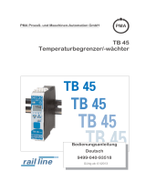
Universal Messumformer / transmitter CI 45 Seite / page 3
Fehlermeldungen / Error messages
Erweiterte Bedienebene / Extended operating level
START
ô
tEmP
OuL.1
InH.1
OuH.1
tF.1
InL.1
Hys.1
L.2
H.2
Hys.2
H.3
L.3
dEL.3
Hys.3
L.1
BH CI 45 Parameterübersicht / Parameter survey
Fnc.1
Fnc.2
Fnc.3
StYP
S.Lin
Corr
Fnc.1
Src.1
Fnc.2
Src.2
Fnc.3
Src.3
0.Act
Lim.1
Lim.2
Lim.3
FAi.1
FAi.2
O.tYP
FAI.F
Sb.Er
O.ut.0
L_r
rES.L
rES.H
Err.r
tArA
HoLd
bAud
Addr
PrtY
dELY
Unit
dP
C.dEL
Func
ôôôô
ô
InP.1 InP.2
Lim
End
sts
ts
ts
t
b.F1
E.tc
ôô
OuL.2
InH.2
OuH.2
b.F
InL.2
tF.1
dEL.1
dEL.2
ô
sts
tsts
ts
ts
ts
ts
ts
t
ô
ô
ôô
ô
ô
ô
ô
ôôôôôôôôô
ôô
EndFunc Inp.1 Inp.2 Lim OUt.1 OUt.2 OUt.3 LOGI othr
4wir
In.F
StYP
S.Lin
Corr
In.F
0.Act
Lim.1
Lim.2
Lim.3
FAi.1
FAi.2
0.Act
Lim.1
Lim.2
Lim.3
FAi.1
FAi.2
O.ut.1
di.Fn
d.Unt
02
SEGm
End
Jede mit diesem Zeichen gekennzeichnete Ebene kann
durch ein Passwort geschützt sein.
Each Level with this sign can be proteced by a password.
PASS
s
t
s
t
s
t
st
ô
ô
ô
ô
ô
ô
ô
s
t
PASS
PASSPASS
antippen
press ô
3 s drücken
press for 3s
ô
s
t
45.0
12FE
ûC
45.0
12FE
PArA
ô
45.0
12FE
CONF
45.0
12FE
CAL
45.0
12FE
END
OuH.1
InH.1 InH.1
OuL.1
InL.1 InL.1
45.0
12FE
FbF.1
üüüä
45.0
12FE
47.3
45.0
12FE
14.2
t
sSchleppzeiger
Slave pointer maximum
maximal
Schleppzeiger
minimum
minimal
Slave pointer
ô
InP.1 InP.2 End
s
ts
t
ô
InL.1
()off
s
t
()off
s
t
st ô
ôô
ô
ô
s
t
OuH.2
InH.2
InH.2
OuL.2
InL.2 InL.1
ô
ô
InL.2
s
t
()off
()off
s
t
+: Reset
halten / hold
halten / hold
E.tc
b.F2
I.Fnc
I.ChG
t.I
P.I Cnt.E
Ou.L
Frq.H
Ou.H
Cnt.d
ô
Cn.Fr
s
t
Frq.L
Frq.F
ô
CntS H.1
I.Fnc
Frq.t
st
ô
ôô
Cn.Fr
Out.L
Frq.L
O.src
O.FAI
FAI.F
Sb.Er
ôô
FAI.F
Sb.Er
Cnt Cnt
Cnt
Out.H
Frq.H
rES.I
rES.C
S.IF

PArA
r
Funcµ
Name Werte-Bereich Beschreibung Ihr
Wert:
tEmP 0...9999 Sondentemperatur für O2Messung µ
t.I 0,1...9999 Integrator-Zeitkonstante [min] µ
P.I -9999...9999 Integrator-Offset µ
InP.1,InP.2
Name W.-ber. Beschreibung
InL.1 (2) -1999...9999 Eingangswert des unteren Skalierungspunktes
OuL.1 (2) -1999...9999 Anzeigewert des unteren Skalierungspunktes
InH.1 (2) -1999...9999 Eingangswert des oberen Skalierungspunktes
OuH.1 (2) -1999...9999 Anzeigewert des oberen Skalierungspunktes
t.F1 (2) 0...999,9 Filterzeitkonstante [s]
b.F1 (2) 0...9999 Filterbandbreite
E.tc1 (2) OFF, 0...100 externe Temperaturkompensation [°C]
Cn.Frµ
Name W.-ber. Beschreibung
Cnt.d 0,1...9999 Zählerteiler
Cnt.S 0...9999 Zählerstartwert
Cnt.E 0...9999 Zählerentwert
Frq.L 0,000...100,0 unterer Eingangswert [kHz]
Ou.L -1999...9999 unterer Ausgabewert [phys.]
Frq.H 0,000...100,0 unterer Eingangswert [kHz]
Ou.H -1999...9999 oberer Ausgabewert [phys.]
Frq.F 0,0...9999 Filterzeitkonstante [s]
Lim
Name W-ber. Beschreibung
L.1 -1999...9999 unterer Grenzwert 1 (L.1< -1999 =off)
H.1 -1999...9999 oberer Grenzwert 1 (H.1< -1999 =off)
HYS.1 0...9999 Hysterese von Grenzwert 1
dEL.1 0...9999 Alarm 1 Verzögerung
L.2 -1999...9999 unterer Grenzwert 2 (L.2< -1999 =off)
H.2 -1999...9999 oberer Grenzwert 2 (H.2< -1999 =off)
HYS.2 0...9999 Hysterese von Grenzwert 2
dEL.2 0...9999 Alarm 2 Verzögerung
L.3 -1999...9999 unterer Grenzwert 3 (L.3< -1999 =off)
H.3 -1999...9999 oberer Grenzwert 3 (H.3< -1999 =off)
HYS.3 0...9999 Hysterese von Grenzwert 3
dEL.3 0...9999 Alarm 3 Verzögerung
ConF
Func
Name W-ber. Beschreibung
Fnc.1 Funktion 1 µ
1Istwert = Inp1
2Differenz (Inp1 - Inp2)
3Max. (Inp1, Inp2)
4Min. (Inp1, Inp2)
5Mittelwert (Inp1, Inp2)
6Umschaltung (Inp1, Inp2)
7O2-Funktion mit konstanter Sondentemperatur
8O2-Funktion mit gemessener Sondentemperatur
9Zähler /Frequenz
10 Istwert = Inp1 (TK von Inp2)
Fnc.2 Funktion 2
0keine Funktion
1Quadrierer
2Quadratwurzel
Fnc.3 Funktion 3 µ
0keine Funktion
1Tara-Funktion
2Sample & Hold
3Integrator
InP.1,Inp2
Name W-ber. Beschreibung
S.tYP Sensortyp
0Thermoelement Typ L (-100...900°C), Fe-CuNi DIN
1Thermoelement Typ J (-100...1200°C), Fe-CuNi
2Thermoelement Typ K (-100...1350°C), NiCr-Ni
3Thermoelement Typ N (-100...1300°C), Nicrosil-Nisil
Name W-ber. Beschreibung
4Thermoelement Typ S (0...1760°C), PtRh-Pt10%
5Thermoelement Typ R (0...1760°C), PtRh-Pt13%
6Thermoelement Typ T (-200...400°C), Cu-CuNi
7Thermoelement Typ C (0...2315°C), W5%Re-W26%Re
8Thermoelement Typ D (0...2315°C), W3%Re-W25%Re
9Thermoelement Typ E (-100...1000°C), NiCr-CuNi
10 Thermoelement Typ B (0/100...1820°C), PtRh-Pt6%
18 Thermoelement Sonder (Linearisierung erforderlich)
20 Pt100 (-200.0 ... 100,0 (150,0) °C)
21 Pt100 (-200.0 ... 850,0 °C)
22 Pt1000 (-200.0...850.0 °C)
23 Spezial 0...4500 Ohm (voreingestellt als KTY11-6)
24 Spezial 0...450 Ohm
25 Spezial 0...1600 Ohm
26 Spezial 0...160 Ohm
30 0...20mA / 4...20 mA
40 0...10V / 2...10 V (nur Inp.1)
41 Spezial (-2,5...115 mV)
42 Spezial (-25...1150 mV)
43 Spezial (-25...90 mV)
44 Spezial (-500...500 mV)
45 Spezial (-5...5 V) (nur Inp.1)
46 Spezial (-10...10 V) (nur Inp.1)
47 Spezial (-200..200 mV)
50 Potentiometer 0...160 Ohm
51 Potentiometer 0...450 Ohm
52 Potentiometer 0...1600 Ohm
53 Potentiometer 0...4500 Ohm
4wir Widerstands-Anschlussart (nur für Inp.1)
03-Leiter-Anschluss
14-Leiter-Anschluss
S.Lin Linearisierung nur einstellbar bei S.tYP:18, 23 ... 47
0Keine
1Sonderlinearisierung. Erstellen der Linearisierungsta-
belle mit BlueControl (Engineering-Tool) möglich. Vor-
eingestellt ist die Kennlinie für KTY 11-6
Temperatursensoren.
Corr Messwertkorrektur / Skalierung
0Keine Korrektur
1Offset-Korrektur (in CAL - Ebene)
22-Punkt-Korrektur (in CAL - Ebene)
3Skalierung (in PArA - Ebene)
In.F OFF,
-1999...
9999
Ersatzwert INP.x
Cn.Frµ
Name W.-ber. Beschreibung
I.Fnc Funktionsauswahl
0Steuereingang
1Aufwärtszähler, positive Flanke
2Aufwärtszähler, negative Flanke
3Abwärtszähler, positive Flanke
4Abwärtszähler, negative Flanke
5Frequenzmessung
Frq.t 0.1...20.0 Frequenz-Totzeit [s]
Lim
Name W-ber. Beschreibung
Fnc.1
(Fnc.2)
(Fnc.3)
Funktion des Grenzwertes 1 (2, 3)
0abgeschaltet
1Messwertüberwachung
2Messwertüberwachung + Speicherung des Alarmzu-
stands. Ein gespeicherter Grenzwert kann über die
Error Liste oder einen digitalen Eingang zurückgesetzt
werden (→LOGI/Err.r).
3Signaländerung in Minuten
4Signaländerung+ Speicherung des Alarmzustands. Ein
gespeicherter Grenzwert kann über die Error Liste oder
einen digitalen Eingang zurückgesetzt werden (→
LOGI/Err.r).
Src.1
(Src.2)
(Src.3)
Quelle für Grenzwert 1 (2, 3)
0Istwert = Absolutalarm
3Messwert INP1
4Messwert INP2
10 Zähler / Frequenz-Messwert
Out.1,Out.2µund Out.3
Name W-ber. Beschreibung
O.tYP Signaltyp (nur bei OUT3 analog)
0Relais / Logik
10 ... 20 mA stetig
24 ... 20 mA stetig
30...10V stetig
42...10V stetig
5Transmitterspeisung
6Frequenz µ
O.Act Wirkungsrichtung von Ausgang OUT1, 2 oder 3
0Direkt / Arbeitsstromprinzip
1Invers / Ruhestromprinzip
Name W-ber. Beschreibung
Lim.1 Meldung Grenzwert 1 (nur bei O.TYP=0 sichtbar)
0nicht aktiv
1aktiv
Lim.2 Meldung Grenzwert 2 (nur bei O.TYP=0 sichtbar)
0nicht aktiv
1aktiv
Lim.3 Meldung Grenzwert 3 (nur bei O.TYP=0 sichtbar)
0nicht aktiv
1aktiv
Cnt Meldung Zählerende µ
0nicht aktiv
1aktiv
FAi.1 Meldung INP1-Fehler (nur bei O.TYP=0 sichtbar)
0nicht aktiv
1aktiv
FAi.2 Meldung INP2-Fehler µ(nur bei O.TYP=0 sichtbar)
0nicht aktiv
1aktiv
FAi.F Meldung Frequenz - Fehler µ
0nicht aktiv
1aktiv
Sb.Er Meldung Systembus - Fehler µ
0nicht aktiv
1aktiv
Out.0 -1999
...9999 Skalierung des Analogausgangs für 0% (0/4mA bzw.0/2V)
Out.1 -1999
...9999 Skalierung des Analogausgangs für 100% (20mA
bzw.10V)
Out.L -1999
...9999 Eingangswert für untere Ausgangsfrequenz µ
Frq.L 0...9999 Untere Ausgangsfrequenz [Hz] µ
Out.H -1999
...9999 Eingangswert für obere Ausgangsfrequenz µ
Frq.H 0...9999 obere Ausgangsfrequenz [Hz] µ
O.Src Signalquelle für Analogausgang OUT3
0nicht aktiv
3Istwert
7Messwert INP1
8Messwert INP2
10 Zähler/ Frequenz-Messwert µ
O.FAI Failverhalten
0upscale
1downscale
LOGI
Name W-ber. Beschreibung
di.Fn Funktion der digitalen Eingänge (gilt für alle Eingänge)
0direkt
1invers
2Tasterfunktion (Einzustellen für 2-Punkt-Bedienung mit
Schnittstelle und di1)
L_r Local / Remote Umschaltung (Remote: Verstellung von
allen Werten über Front ist blockiert)
0keine Funktion (Umschalten über Schnittstelle ist möglich)
1immer aktiv
2di1 schaltet
7Limit 1 schaltet
8Limit 2 schaltet
9Limit 3 schaltet
Err.r Rücksetzen aller gespeicherten Einträge der Errorliste
0keine Funktion (Umschalten über Schnittstelle ist möglich)
2di1 schaltet
7Limit 1 schaltet
8Limit 2 schaltet
9Limit 3 schaltet
I.ChG Umschaltung Inp1./ Inp2
0keine Funktion (Umschalten über Schnittstelle ist möglich)
1di1 schaltet
7Limit 1 schaltet
8Limit 2 schaltet
9Limit 3 schaltet
tArA Tara-Funktion µ
0keine Funktion (Umschalten über Schnittstelle ist möglich)
2di1 schaltet
7Limit 1 schaltet
8Limit 2 schaltet
9Limit 3 schaltet
HoLd Sample & Hold - Funktion µ
0keine Funktion (Umschalten über Schnittstelle ist möglich)
2di1 schaltet
7Limit 1 schaltet
8Limit 2 schaltet
9Limit 3 schaltet
rES.L Reset Minimalwert
0keine Funktion (Umschalten über Schnittstelle ist möglich)
2di1 schaltet
7Limit 1 schaltet
8Limit 2 schaltet
9Limit 3 schaltet
Name W-ber. Beschreibung
rES.H Reset Maximalwert
0keine Funktion (Umschalten über Schnittstelle ist möglich)
2di1 schaltet
7Limit 1 schaltet
8Limit 2 schaltet
9Limit 3 schaltet
rES.I Reset Integrator µ
0keine Funktion (Umschalten über Schnittstelle ist möglich)
2di1 schaltet
6Reset-Tasten schalten
7Limit 1 schaltet
8Limit 2 schaltet
9Limit 3 schaltet
rES.C Zähler - Reset µ
0keine Funktion (Umschalten über Schnittstelle ist möglich)
6Reset-Tasten schalten
7Limit 1 schaltet
8Limit 2 schaltet
9Limit 3 schaltet
othr
Name W-ber. Beschreibung
bAud Baudrate der Schnittstelle µ
02400 Baud
14800 Baud
29600 Baud
319200 Baud
438400 Baud
Addr 1...247 Adresse auf der Schnittstelle µ
PrtY Parität der Daten auf der Schnittstelle µ
0kein Parity (2 Stopbits)
1gerade Parity
2ungerade Parity
3kein Parity mit 1 Stopbit
dELY 0...200 Antwortverzögerung [ms] µ
S.IF Systemschnittstelle µ
0abgeschaltet
1eingeschaltet
d.Unt Anzeigeeinheit (Darstellung auf Display)
0ohne Einheit
1Temperatur-Einheit (siehe Datum Unit)
2O2 - Einheit
3%
4bar
5mbar
6Pa
7kPa
8psi
9l
10 l/s
11 l/min
12 Ohm
13 kOhm
14 m
15 A
16 mA
17 V
18 mV
19 kg
20 g
21 t
22 Text der physikalischen Einheit (vorgegeben über T.Unit)
O2 Parametereinheit für O2 µ
0Parameter in ppm
1Parameter in %
Unit Einheit
1°C
2°F
3Kelvin
dP Dezimalpunkt (max. Nachkommastellen)
0keine Dezimalstelle
11 Dezimalstelle
22 Dezimalstellen
33 Dezimalstellen
SEGm Anzeigensegment-Zuordnung
0OUT1, OUT2
1INP1, INP2
C.dEl 0..200 Modem delay [ms]
µoptional
+Abhängig von der Geräteversion und der Konfiguration werden nicht
benötigte Parameter ausgeblendet.
Universal Messumformer / transmitter CI 45 Seite / page 4
A3 auf A6 gefaltet , SW-Druck Normalpapier weiß 80g/m2
/