
Installation Guide
Electrical Actuating Module PVEP and PVEP-F
for PVG 32 and PVG 100
© Danfoss A/S, 2014-03 520L0921 • Rev CC • Mar 2014 1
157R9900
157R9900
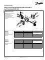
Oliestrømmens retning for
standard monterede grupper.
Oil flow direction for standard
assembled groups.
Richtung des Ölstroms für
Standard-Baugruppen.
Sens du débit pour ensembles
standard.
Aktivering
Activation
Betätigung
Commande
PVEP standard version:
11034832
Duty cycle A-signal (pin 1) Duty cycle B-signal (pin 2) Function
0% 0%
Neutral10% 0%
0% 10%
≥≥10 % ≥≥10 % Fault (Error)
0% 80% B-port full flow
80% 0% A-port full flow
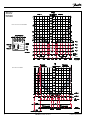
Duty cycle A-signal (pin 1) Duty cycle B-signal (pin 2) Function
0% 0%
Neutral10% 0%
0% 10%
≥≥10% ≥≥10% Fault (Error)
0% 10→80% B-port: 0→5.5 mm
10→80% 0% A-port: 0→5.5 mm
90% 90% Float A-port (8mm)
≥90% 0% Fault (Error)
0% ≥90% Fault (Error)
Aktivering
Activation
Betätigung
Commande
PVEP-F (float) version:
157B4753
V310159.A
P
A
A
B
PVEP/
PVEP-F

2 520L0921 • Rev CC • Mar 2014 © Danfoss A/S, 2014-03
P301 024
PWM
Flow-curve for standard PVEP
Flow-curve for PVEP-F
Aktivering
Activation
Betätigung
Commande

© Danfoss A/S, 2014-03 520L0921 • Rev CC • Mar 2014 3
NB:
Pakningen i Deutsch-stikket samt brug af 1.5 mm
2
ledning i alle forbindelser, er afgørende for at
korrekt tæthed af stikket opnås.
NB:
The seal in the Deutsch-connector and the use of
1.5 mm
2
lines in all connections are crucial for
correctly sealing the connector.
NB:
Die Dichtung im Deutsch-Stecker sowie die
Verwendung von 1.5 mm
2
Leitungen in allen
Anschlüssen sind für die Dichtheit des Steckers von
entscheidendem Einfluss.
NB:
Le joint de la prise Deutsch ainsi que l’utilisation des
fils de 1.5 mm
2
dans tous les raccordements jouent
un rôle essentiel dans la qualité de l'étancheité de la
prise.
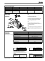
Function LED status Error output Reaction time Memory
Normal mode constant green low <2V)
Error mode active FMS
Input signal monitoring blinking red
high (~ UDC) 0.5 s yesTransducer monitoring constant red
Closed loop monitoring constant red
Fault monitoring thruth table
Montage af PVE
Installation of PVE
Montage von PVE
Installation de
Tekniske data
Technical data
Technische Daten
Caractéristiques Techniques
Function PVEP and PVEP-F
Supply voltage U
DC
range 11-32 V
Supply voltage U
DC max. ripple
5 %
Supply voltage U
DC
(max. 5 min) 36 V
PWM control range 10 - 80 %
PWM float position control PWM_A = PWM_B = 90 %
PWM frequency 100 - 1000 Hz
PWM input voltage swing 0 - UDC
PWM trigger point 70 % of V bat
Input impedance (standard pull down) 5 kΩ
Power consumption 7 W
Error voltage: Fault V bat
Error voltage: No fault < 2 V
Oil viscosity
Oil
viscosity
range 12 - 75 mm2/s [65 - 347 SUS]
min. 4 mm2/s [39 SUS]
max. 460 mm2/s [2128 SUS]
Oil temperature
Oil
temperature
range 30 - 60˚C [86 -140˚F]
min. -30˚C [-22˚F]
max. 90˚C [194˚F]
Filtering
Filtering in the
hydraulic system
Max. allowed degree of
contamination (ISO 4406,
1999 version): 18/16/13
Bemærk: Maksimum opstartsviskositet
Note: Max. start up viscosity 2500 mm
2
/s
Beachte: Maximale Viskosität bei Inbetriebnahme
Remarque : Viscosité maximale au démarrage 2500 mm
2
/s
Pilot pressure
Pilot pressure
(relative to T
pressure)
nom. 13.5 bar [196 psi]
min. 10 bar [145 psi]
max. 15 bar [217 psi]
All connector terminals are short-circuit protected, and protected against reverse connection ( and their combinations).
Connecting error pins from two or more PVE’s will cause the surveillance system to malfunction
WWARNING

4 520L0921 • Rev CC • Mar 2014 © Danfoss A/S, 2014-03
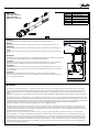
Udluftning
Hvis gruppen er monteret vertikalt, anbefales det at udlufte ved justerskrue (Pos. A).
Bleeding
If the group is installed vertically, it is recommended to bleed it at the adjusting screws (Pos. A).
Entlüftung
Wenn die Gruppe vertikal montiert ist, empfehlen wir an den Justieschrauben zu entlüften (Pos. A).
Purge
Si l'ensemble est monté verticalement, il est recommandé de le purger au moyen des vis d'ajustage
(Pos. A).
137.5[5.414]
170[6.69]
T P
LS
A
V310136.A
Beskyttelse
PVEP/PVEP-F overholder tæthedsgrad IP 67 og IP 69k i henhold til IEC 529. Det anbefales dog, at PVE'en
på særligt udsatte steder beskyttes i form af en afskærmning eller lignende.
Protection
PVEP/PVEP-F comply with protection class IP 67 og IP 69k in IEC 529. However, it is recommended to
additionally shield all such PVE-modules that are exposed to particularly moist conditions.
Schutzgrad
PVEP/PVEP-F erfüllt die Schutzart IP 67 og IP 69k in IEC 529. Wenn die PVE-Module aber besonders
nassen Bedingungen ausgesetzt sind, werden weitere Schutzmaßnahmen in Form von einer Abschir-
mung empfohlen.
Protection
PVEP/PVEP-F possèdent le degré de protection IP67 og IP 69k conformément à la IEC 529.
Dans les zones particulièrement exposées, il est cependant conseillé de protéger le PVE à l’aide d’un
écran ou d’un dispositif similaire.
Alle mærker og typer af retningsventiler – også proportional ventiler – kan svigte og forårsage alvorlig skade. Det er derfor vigtigt at analysere
maskinen i alle enkeltheder. Da proportionalventiler anvendes under mange forskellige driftsbetingelser og i mange forskellige maskiner, er det
alene maskinproducentens ansvar at træffe det endelige produktvalg og sikre at samtlige maskinens krav til ydelse, sikkerhed og advarsler er
opfyldt.
Ved valg af reguleringssystem – og sikkerhedsniveau – kan man f.eks. støtte sig til EN954-1 (sikkerhedsrelaterede bestanddele i reguleringssystemet.)
Alle Fabrikate und Typen von Wegeventilen – einschließlich Proportionalventile – können versagen und schlimme Unfälle verursachen. Es ist daher
wichtig, die Anwendung in allen Details zu analysieren. Weil Proportionalventile unter vielen unterschiedlichen Arbeitsbedingungen und in vielen
verschiedenen Anwendungen benutzt werden, trägt allein der Maschinenhersteller die Verantwortung für seine endgültige Wahl von Produkt, und
er ist ebenfalls dafür verantwortlich, dass alle Leistungs-, Sicherheits- und Warnungsanforderungen an seine Maschine erfüllt sind.
Zur Wahl vom Reglersystem und Sicherheitsniveau kann man sich z.B. auf EN954-1 stützen.
All marks and all types of directional control valves – inclusive proportional valves – can fail and cause serious damage. It is therefore important
to analyse all aspects of the application. Because the proportional valves are used in many different operation conditions and applications, the
manufacturer of the application is alone responsible for making the final selection of the products – and assuring that all performance, safety and
warning requirements of the application are met.
The process of choosing the control system – and safety level – could e.g. be governed by EN 954-1 (Safety related parts of control system).
Tous les distributeurs - y compris les distributeurs proportionnels - peuvent tomber en panne et entraîner de sérieux dommages. C’est la raison
pour laquelle il est important d’analyser chaque aspect de l’application. Les vannes proportionnelles étant utilisées dans de nombreuses condi-
tions d’exploitation et applications différentes, le fabricant de l’application porte l’entière responsabilité de la sélection finale des produits et du
respect des exigences en matière de rendement, de sécurité et d’avertissement. Le choix du système de commande – et du niveau de sécurité
– peut être fait par exemple sur la base de la norme EN 954-1 (parties du système de commande relatives à la sécurité). Se reporter également à
Information technique pour PVE série 4.
WWARNING
Kabel med stik
Cable with connector
Kabel mit Stecker
Câble avec connecteur
Pin 1 Hvid, White, Weiss, Blance
Pin 2 Blå, Blue, Blau, Bleu
Pin 3 Gul, Yellow, Gelb, Jaune
Pin 4 Rød, Red, Rot, Rouge
Pin 5 Sort, Black, Schwarz, Noir
Pin 6 Grøn, Green, Grün, Vert
-
 1
1
-
 2
2
-
 3
3
-
 4
4


Danfoss PVG 100 Installationsanleitung
- Typ
- Installationsanleitung
- Dieses Handbuch eignet sich auch für
in anderen Sprachen
- English: Danfoss PVG 100 Installation guide
- français: Danfoss PVG 100 Guide d'installation
- dansk: Danfoss PVG 100 Installationsvejledning
Verwandte Artikel
-
Danfoss PVG 16 Installationsanleitung
-
Danfoss PVG 120 Installationsanleitung
-
Danfoss PVG 32 Installationsanleitung
-
-
-
Danfoss PVHC Benutzerhandbuch
-
-
-
-