Danfoss PVG Splitter Gear Box Benutzerhandbuch
- Kategorie
- Spielzeuge
- Typ
- Benutzerhandbuch

powersolutions.danfoss.com
MAKING MODERN LIVING POSSIBLE
Technical Information
Pump Splitter Gearboxes
PVG
Phased Out Products

Technical Information Pump Splitter Gearboxes, PVG
368498A • Rev BA • Sep 20132
General Description
For more then two decades
SAUER-SUNDSTRAND mechanical gear-
boxes have been developed for a wide range of
hydrostatic power transmission equipment.
Features
• optimized for SAUER-SUNDSTRAND
hydrostatics
• modern computer design
e.g. gear life calculation according to
DIN 3990
• high lifetime
• robust housing
• heavy duty bearings
• O-ring housing sealing
• shaft sealing for high
temperatures
• gears hardened and ground
• high quality level through
production on modern numeric
controlled machine
• all gears with splash lubrication
Allgemeine Beschreibung
SAUER-SUNDSTRAND mechanische
Getriebe werden seit über 20 Jahren in breiter
Palette für die Hydrostatik mobiler Arbeits-
fahrzeuge hergestellt.
Besondere technische Merkmale
• optimal auf SAUER-SUNDTRAND
Hydrostatik abgestimmt
• Auslegung mit modernen EDV-Methoden
z.B. Tragfähigkeitsberechnung nach
DIN 3990
• hohe Lebensdauer
• robuste Gehäuse
• solide Lagerungen
• O-Ring Gehäuseabdichtung
• Wellendichtung mit Hochtemperatur-
eignung
• Verzahnung gehärtet und geschliffen
• Hoher Qualitätsstandard durch
Fertigung auf modernen CNC-
Bearbeitungszentren
• alle Getriebe mit Tauchschmierung
Danfoss mechanical gear-
Danfoss mechanische
Danfoss
Danfoss
Phased Out Products

Technical Information Pump Splitter Gearboxes, PVG
368498A • Rev BA • Sep 2013 3
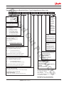
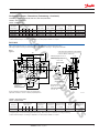
Typenbezeichnung und Bestellschlüssel • Type Designation and Order Code
--
-
--
-
--
Bauart • Design
PVG = Pumpen-
Verteilergetriebe
Pump Splitter
Gearbox
Baugröße • Frame Size
siehe Tabelle Abmessungen
see Table Dimensions
Pumpenanbau
Pump Adaptation
1=einseitig • one-sided
2=zweiseitig • two-sided
5=einseitig (180° gedreht)
one-sided (turned 180°)
6=zweiseitig (180° gedreht)
two-sided (turned 180°)
Übersetzungsangaben • Gear Ratio Data
siehe Ausführungsdarstellung,
z.B. Seite 5, Tabelle 2
see configuration drawing e.g.
page 5, Table 2
Pumpen -
Anbauten
unten bzw. oben
2-stellige
Buchstaben -
kombination
werksseitig
festgelegt
Pump
Adaptation
below, above
respectively
2-digits letter
combination
determined by
the factory
Anbau Antriebswelle,abtriebsseitig
2-stellige Buchstabenkombination
werksseitig festgelegt
Drive Shaft Adaptation,
output end (PTO)
2-digits letter combination
determined by the factory
Ausführungskennzeichen für Sonder-
Anbauten der Antriebswelle
2-stellige Buchstabenkombination
werksseitig festgelegt
Configuration Code for Special Adaptations,
Input Shaft
2-digits letter combination
determined by the factory
-P V G -
Gelenkwellenflansch • Universal Joint Flange
siehe Ausführungsdarstellung auf Seite 7
see configuration drawing e.g. page 7
A=ohne Gelenkwellenflansch
without Universal Joint Flange
weitere Kennbuchstaben werksseitig festgelegt
further code letters determined by the factory
SAE-Kupplungsflansch • SAE-Engine Flywheel Housing
siehe Ausführungsdarstellung auf Seite 7
see configuration drawing e.g. page 7
A=ohne SAE-Kupplungsflansch
without SAE-Engine Flywheel Housing
weitere Kennbuchstaben werksseitig festgelegt
further code letters determined by the factory
Eingangsdrehzahl • Input speed
Ausgangsdrehzahl • Output speed
i =
Ausführungskennzeichen für Antriebswelle
(mit oder ohne Durchtrieb)
2-stellige Buchstabenkombination werksseitig festgelegt
Configuration code for input shaft
(with or without PTO)
2-digits letter combination determined by the factory
Bestellbeispiel: PVG 160-3, i = 0,91, ohne
Durchtrieb, SAE-Kupplungsflansch, Größe 1
für 2x 90L100, 1x 90L055
Order Example: PVG 160-3, i = 0,91,
without PTO, SAE-Engine Flywheel Housing No. 1
for 2x 90L100, 1x 90L055
Bestellbezeichnung • Order Designation:
PVG 160-3 1091 AB KG NN NN EC EC DG
Pumpen- Anbau, links
2-stellige
Buchstabenkombination
werksseitig festgelegt
Pump Adaptation, left
2-digits letter combination
determined by the factory
Pumpen- Anbau, rechts
2-stellige
Buchstabenkombination
werksseitig festgelegt
Pump Adaptation, right
2-digits letter combination
determined by the factory
Phased Out Products

Technical Information Pump Splitter Gearboxes, PVG
368498A • Rev BA • Sep 20134
Baugröße j Keilwellenprofil
Frame Size a b e f g h i j Input shaft parallel side spline k
PVG 40 122,5 - 392 451 43,5 43,5 - W 35x 2 x 16 x 9 g / DIN 5480 96
PVG 140-2 132 - 500 250 53 73 125 B 45 x 41 / DIN 5482 127
PVG 160-2 180 90 660 400 50 75 250 B 45 x 41 / DIN 5482 128
PVG 500-2 220 - 800 400 57 66,5 200 B 58 x 53 / DIN 5482 147
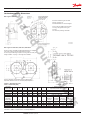
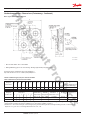
Geräteabmessungen • Dimensions
Bild • Figure 1: PVG 40
Bild • Figure 2: PVG 140-2, PVG 160-2, PVG 500-2
Für diese Typen sind SAE-und Gelenkwellenflansche verfügbar,
siehe Seite 7. Durchgehende Antriebswelle möglich.
For these types SAE engine flywheel housing and universal joint
flange available, see page 7. Through drive available.
ABCD
Baugröße Gewinde Gewinde
SAE-Flansch Gelenk. Flansch
Frame Size l m o p q r s thread thread
SAE output flange Size of un.joint fl.
PVG 40 46 142 - - - - - - M 12 3 or 4 -
PVG 140-2 90 217 43 54 - 45 90 M 16 M 12 1 - 4
100 -120 -150
PVG 160-2 90 218 43 64 - 70 140 M 16 M 12 1 - 4
100 -120 -150
PVG 500-2 97 244 43 15 90 45 90 M 16 M 16 1 - 4
150 - 180
PVG 40 = 2 Anschlüsse • 2 Pump adaptation / PVG 140-2 = 2-4 Anschlüsse • 2-4 Pump adaptation
PVG 160-2 + 500-2 = 2-5 Anschlüsse • 2-5 Pump adaptation
Tabelle 1: Abmessungen (mm)
Table 1: Dimensions (mm)
Achtung: Getriebe sind pumpenseitig nicht abgedichtet !
Important: Gearboxes are not sealed at pump adaptation !
Bei dieser Ausführung ist der SAE-
Flansch angegossen.
Gelenkwellenflansche nicht verfügbar.
For this type the SAE engine flywheel
housing is integrated into the gear
housing.
No universal joint flange available.
P001 024/1
P001 024/2
P000 353
* PVG 500 = 36
Phased Out Products

Technical Information Pump Splitter Gearboxes, PVG
368498A • Rev BA • Sep 2013 5
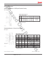
Geräteabmessungen • Dimensions (Fortsetzung • Continued)
Fortsetzung • Continuation PVG 40, PVG 140-2, PVG 160-2, PVG 500-2,
Übersetzungen
Eingangsdrehmom. Eingangsdrehzahl Schmierfl.keitsinhalt Masse Pumpen Baureihe
Baugröße Gear ratios
Input torque Input speed Lubrication oil vol.
1
)
Weight Pumps Series
2
)
Frame Size i
1
i
2
i
3
i
4
i
5
Nm • ft. lbs min
-1
• RPM l • US-gal kg • Lb
PVG 40 0,70 - 0,82 - 0,98 450 • 330 4000 0,8 • 0,2 30 • 66
BR90 / BG 042
⇒
055
PVG 140-2 0,63 0,73 0,82 0,91 1,02 800 • 590 4000 1,5 • 0,4 55 • 121
BR90 / BG 042
⇒
075
PVG 160-2 0,65 0,75 0,82 0,91 1,02 1600 • 1175 3000 2,5 • 0,7 95 • 209
BR90 / BG 042
⇒
130
PVG 500-2 0,74 0,81 0,89 0,98 1,2 5000 • 3675 2500 5 • 1,3 200 • 441
BR20 / BG
⇒
2/334
Tabelle 2: Technische Daten
Table 2: Technical Data
1
) Angaben gelten nur für den Einbau gemäß Darstellung • Data valid only for installation according to drawing
2
) Anbau anderer Pumpen auf Anfrage • Adaptations for other pumps available on request
PVG 160-3
SAE- und Gelenkwellenflansche verfügbar, siehe Seite 7. Durchgehende Antriebswelle möglich.
SAE engine flywheel housing and universal joint flange available, see page 7. Through drive available.
Bild 3
Figure 3
Tabelle 3: Technische Daten
Table 3: Technical Data
Achtung: Getriebe sind pumpenseitig nicht abgedichtet !
Important: Gearboxes are not sealed at pump adaptation !
Übersetzungen
Eingangsdrehmom. Eingangsdrehzahl Schmierfl.keitsinhalt Masse Pumpen Baureihe
Baugröße Gear ratios
Input torque Input speed Lubrication oil vol.
1
)
Weight Pumps Series
2
)
Frame Size i
1
i
2
i
3
i
4
i
5
Nm • ft. lbs min
-1
• RPM l • US-gal kg • Lb
PVG 160-3 0,65 0,75 0,82 0,91 1,02 1600 • 1175 3000 3,5 • 0,9 120 • 265
BR90 / BG 042
⇒
130
PVG 160-3 = 3 bis 7 Anschlüsse möglich • 3 to 7 adaptation poss.
1
) Angaben gelten nur für den Einbau gemäß Darstellung • Data valid only for installation according to drawing
2
) Anbau anderer Pumpen auf Anfrage • Adaptations for other pumps available on request
P001 391
180
180
332,5
665
30
M16
53
53
201335
307
635
170
340
90
238
201
356
Schmierflüssig-
keitsstand
Lubrication
Oil Level
Schmierflüssigkeits-
ablaßstutzen
Lubrication Oil Outlet
ø240
5040
M12
ø44,5
h11
ø145
ø170
h7
52
70
75
90
128
218
Schmierflüssigkeitseinfüllstutzen und Entlüftung
Lubrication Oil Inlet and Breather
SAE-Kupplungsflansch, Gr. 1-4
SAE Output Flange, Size 1-4
Zahnwelle
Spline Shaft
(B 45x41, DIN 5482)
Gelenkwellenflansch
Größe 100, 120, 150
Size of Un. Joint Flanges
100, 120, 150
M12, 22 tief
M12, 22 deep
28
Phased Out Products

Technical Information Pump Splitter Gearboxes, PVG
368498A • Rev BA • Sep 20136
Geräteabmessungen • Dimensions (Fortsetzung • Continued)
Bild • Figure 4: PVG 100-4, PVG 160-4
* Nicht bei PVG 100-4 • Not for PVG 100-4
** O-Ring Abdichtung gehört zum Lieferumfang • O-Ring supplied with pump splitter gear box
Achtung: Getriebe sind pumpenseitig nicht abgedichtet !
Important: Gearboxes are not sealed at pump adaptation !
BaugrößeABCDEFGHKLMNO P
Frame Size Lieferbare SAE-Flansche
available SAE flange
PVG 100-4 620 565 176 150 337 208 50 78 14 37 63 140 105 2, 3, 4
PVG 160-4 640 635 162,5 162,5 320 218 52 75 14 47 83 162,5 162,5 1, 2, 3
Tabelle 4: Abmessungen (mm) und Technische Daten
Table 4: Dimensions (mm) and Technical Data
Übersetzungen Eingangs- Eingangs- Schmierflüssig- Masse Pumpen Baureihe
Baugröße Gear ratios drehmoment drehzahl keitsinhalt
1
) Weight Pump Series
2
)
Frame size i
1
i
2
i
3
i
4
i
5
i
6
Input torque Input speed Lubrication oil vol.
Nm • ft. lbs min
-1
• RPM l • US-gal kg • Lb
PVG 100-4
3
) 0,60 0,70 0,77 0,89 1,01 1,13 1000 • 735 3000 6 • 1,6 140 • 309
BR 90 / BG 042
⇒
100
PVG 160-4 0,60 0,64 0,72 0,81 0,92 1,02 2200 • 1620 2500 4 • 1,1 200 • 441
BR 90 / BG 042
⇒
130
1
) Angaben gelten nur für den Einbau gemäß Darstellung • Data valid only for installation according to drawing.
2
) Anbau anderer Pumpen auf Anfrage • Adaptations for other pumps available on request.
3
) Wahlweise 1 oder 2 Übersetzungen, Übersetzungssprung- und Anordnung der Übersetzungen beliebig auf A, B, C oder D verteilt.
Optional 1 or 2 gear- ratios, interchangeable between A, B, C, or D.
P000 744/1
P000 744/2
Phased Out Products

Technical Information Pump Splitter Gearboxes, PVG
368498A • Rev BA • Sep 2013 7
Zubehör • Accessories
SAE-Kupplungsflansche • SAE-Engine Flywheels Housing
Bild • Figure 5
P000 358
Gelenkwellenflansche • Universal Joint Flanges
Bild • Figure 6
øA øB øC øD H (10)
ab
DIN 5482
100 84 57 8 A 45 x 41 85 83
120 101,5 75 8 A 45 x 41 84,5 82,5
150 130 90 10+12 A 45 x 41 85 82,5
150 130 90 12 A 58 x 53 82,3 80
180 155,5 110 14 A 58 x 53 82,3 80
Tabelle 6: Abmessungen (mm)
Table 6: Dimensions (mm)
cdey Bestell- Nr.* zum Anbau an PVG
Order No.* for PVG adaptation
10 76 25 6 400 036 140, 160
12 75,5 25 8 400 044 140, 160
12 76 25
je 8 (8 each)
400 051 140, 160
12 67,3 10 8 442 046 500
12 67,3 10 8 442 053 500
Technische Änderungen vorbehalten. Subject to technical changes.
P000 357
* einschließlich Anbauteile
* including mounting parts
Größe øA øB øC øD Bestell-Nr.* zum Anbau an PVG
Unit Order No.* for PVG adaptation
1 552 530,2 511,18 12 400 101
2 489 466,7 447,7 11 400 069
3 451 428,6 409,58 11 400 077
4 415 381 361,95 11 400 085
Tabelle 5: Abmessungen (mm)
Table 5: Dimensions (mm)
PVG 140-2
PVG 160-2
PVG 160-3
PVG 500-2
* einschließlich Anbauteile
* including mounting parts
Phased Out Products

Comatrol
www.comatrol.com
Schwarzmüller-Inverter
www.schwarzmueller-
inverter.com
Turolla
www.turollaocg.com
Valmova
www.valmova.com
Hydro-Gear
www.hydro-gear.com
Daikin-Sauer-Danfoss
www.daikin-sauer-danfoss.com
Danfoss Power Solutions is a global manufacturer and supplier of high-quality hydraulic and
electronic components. We specialize in providing state-of-the-art technology and solutions that
excel in the harsh operating conditions of the mobile off -highway market. Building on our extensive
applications expertise, we work closely with our customers to ensure exceptional performance for a
broad range of off -highway vehicles.
We help OEMs around the world speed up system development, reduce costs and bring vehicles to
market faster.
Danfoss – Your Strongest Partner in Mobile Hydraulics.
Go to www.powersolutions.danfoss.com for further product information.
Wherever off -highway vehicles are at work, so is Danfoss.
We off er expert worldwide support for our customers, ensuring the best possible solutions for
outstanding performance. And with an extensive network of Global Service Partners, we also provide
comprehensive global service for all of our components.
Please contact the Danfoss Power Solution representative nearest you.
Products we off er:
Bent Axis Motors
Closed Circuit Axial Piston
Pumps and Motors
Displays
Electrohydraulic Power
Steering
Electrohydraulics
Hydraulic Power Steering
Integrated Systems
Joysticks and Control
Handles
Microcontrollers and
Software
Open Circuit Axial Piston
Pumps
Orbital Motors
PLUS+1® GUIDE
Proportional Valves
Sensors
Steering
Transit Mixer Drives
Local address:
Danfoss can accept no responsibility for possible errors in catalogues, brochures and other printed material. Danfoss reserves the right to alter its products without notice. This also applies to products
already on order provided that such alterations can be made without subsequential changes being necessary in specifications already agreed.
All trademarks in this material are property of the respective companies. Danfoss and the Danfoss logotype are trademarks of Danfoss A/S. All rights reserved.
Danfoss
Power Solutions
22F, Block C, Yishan Rd
Shanghai 200233, China
Phone: +86 21 3418 5200
Danfoss
Power Solutions GmbH & Co. OHG
Krokamp 35
D-24539 Neumünster, Germany
Phone: +49 4321 871 0
Danfoss
Power Solutions ApS
Nordborgvej 81
DK-6430 Nordborg, Denmark
Phone: +45 7488 2222
Danfoss
Power Solutions US Company
2800 East 13th Street
Ames, IA 50010, USA
Phone: +1 515 239 6000
368498A • Rev BA • Sep 2013 www.danfoss.com © Danfoss, 2013-09
Phased Out Products
-
 1
1
-
 2
2
-
 3
3
-
 4
4
-
 5
5
-
 6
6
-
 7
7
-
 8
8


Danfoss PVG Splitter Gear Box Benutzerhandbuch
- Kategorie
- Spielzeuge
- Typ
- Benutzerhandbuch
Verwandte Artikel
-
Danfoss PVG 120 Installationsanleitung
-
-
-
-
Danfoss PVG 32 Installationsanleitung
-
Danfoss PVG 16 Installationsanleitung
-
-