
V310178.A
MA
P
LS
Installation Guide
Proportional Valve
PVG 120
© Danfoss A/S, 2015-02 520L0526 • Rev CC • Feb 2015 1
155R9959
155R9959
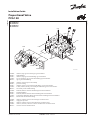
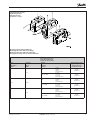
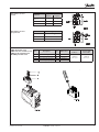
Identikation
Identication
Identikation
Identication
C: PVG – nummer, uge og år for montage og serienummer
D: PVP – trykindstilling
E: PVP – nummer, uge og år for fremstilling og serienummer
F: PVB – A-port, nummer, uge og år for fremstilling og serienummer
G: PVT – uge og år for fremstilling
C: PVG – number, week and year of assembly
D: PVP – pressure setting
E: PVP – number, week, year and day manufacturing, issue and series No.
F: PVB – A-Port, number, week, year and day manufacturing, issue and series No.
G: PVT – week and year of manufacturing
C: PVG – Nummer, Woche und Jahr der Montage und Seriennummer
D: PVP – Druckeinstellung
E: PVP – Nummer, Woche und Jahr der Herstellung und Seriennummer
F: PVB – A-Anschluss, Nummer, Woche und Jahr der Herstellung und Seriennummer
G: PVT – Woche und Jahr der Herstellung
C: PVG – numéro, semaine et année de montage et numéro sériel
D: PVP – réglage de pression
E: PVP – numéro, semaine et année de fabrication et numéro sériel
F: PVB – orice-A, numéro, semaine et année de fabrication et numéro sériel
G: PVT – semaine et année de fabrication
PVMD
PVH
F
D
C
PVP
PVM
PVB
PVT
E
G
PVEO
PVEH
S
MA
P
PVM
V310156.A

2 520L0526 • Rev CC • Feb 2015 © Danfoss A/S, 2015-02
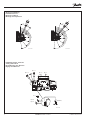
60 Nm
[530 lbf•in]
60 Nm
[530 lbf•in]
190 [7.48]*
100 [3.94]*
190 [7.48]*
100 [3.94]*
105 [4.13]
L
4xM12x18
[4x7/16-14UNCx0.7]
V310179.A
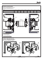
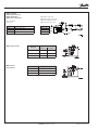
Montering og orientering af stik
Installation and plug orientation
Montage und Ausrichtung des Steckers
Montage et orientation de la prise
PVB 1 2 3 4 5 6 7 8
L mm 168 235 302 369 436 503 570 637
L in 6.61 9.25 11.88 14.53 17.17 19.80 22.44 25.08
* Plads til demontage
* Room for dismantling
* Platz für Demontage
* Espace pour démontage
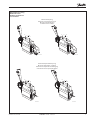
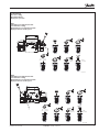
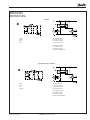
Tilslutning – PVP, pumpesidemodul
Connection – PVP, pump side module
Anschluss – PVP, pumpenseitiges Modul
Raccordement – PVP, plaque d'entrée

© Danfoss A/S, 2015-02 520L0526 • Rev CC • Feb 2015 3
A
P A
PA
PB
P
B
V310163.A
A
P A
PA
PB
P
B
V310170.A
A
B
P B
V310169.A
A
B
P B
V310162.A
Oliestrømmens retning
Oil ow direction
Richtung des Ölstroms
Sens du débit
Mekanisk betjening
Mechanical actuation/electrical
Mechanische Betätigung
Commande mécanique
Mekanisk/hydraulisk betjening
Mechanical/hydraulic actuation
Mechanische/hydraulische Betätigung
Commande mécanique/hydraulique

4 520L0526 • Rev CC • Feb 2015 © Danfoss A/S, 2015-02
Tilslutningsgevind type G (ISO 228/1)
Connection threads type G (ISO 228/1)
Anschlussgewinde Typ G (ISO 228/1)
Filetage de raccordement type G (ISO 228/1)
Maks. tilspændingsmoment
Max. tightening torques
Max. Anzugsmomente
Couples de serrage maxi
PA, PB MA LS, LX, PP
Tætning Gevind
Sealing Thread
Dichtung Gewinde
Etanchéite Filetage
G 1/4 G 1/4 G 3/8
med stålskive
with steel washer
mit Stahlscheibe
avec rondelle en acier
35 Nm [310 lbf·in] 40 Nm [350 lbf·in] 60 Nm [530 lbf·in]
med kobberskive
With cooper washer
mit Kupferscheibe
avec rondelle en cuivre
30 Nm [270 lbf·in] 20 Nm [180 lbf·in] 35 Nm [310 lbf·in]
med aluminiumsskive
with aluminium washer
mit Aluminiumscheibe
avec rondelle en aluminium
30 Nm [270 lbf.in] 30 Nm [270 lbf.in] 40 Nm [350 lbf·in]
med skærekant
with cutting edge
mit Dichtkante
tranchant
35 Nm [310 lbf.in] 40 Nm [350 lbf.in] 60 Nm [530 lbf·in]
Tilspændingsmomenter
Tightening torques
Anzugsmomente
Couples de serrage
Nominel tryk
Rated pressure
Nomineller Druck
Pression nominale
Product Rated pressure
PVG 120 400 bar [58.02 psi]
PVG 120/32 w.PVS 300 bar [4351 psi]
PVG 120/32 w.PVSI 350 bar [5076 psi]
PVG 120 w. HIC steel 350 bar [5076 psi]
PVG 120 w. HIC aluminium 210 bar [3046 psi]
UN og UNF tilslutningsgevind med O-ringstætning
UN and UNF connection threads – O-ring boss port
UN und UNF Anschlussgewinde mit O-ringsdichtung
Filetage de raccordement UN et UNF avec cône pour joint torique
Maks. tilspændingsmoment
Max. tightening torques
Max. Anzugsmomente
Couples de serrage maxi
P A/B T PA/PB MA LS,LX,PP
Tætning Gevind
Sealing Thread
Dichtung Gewinde
Etanchéite Filetage
1 5/16 in-12 UN 1 1/16 in-12 UN 1 5/16 in-12 UN 1/2 in-20 UNF 1/2 in-20 UNF 3/4 in-20 UNF
O-ring
O-ring
O-ring
Joint torique
160 Nm
[1410 in-lbs]
120 Nm
[1060 in-lbs]
160 Nm
[1410 in-lbs]
30 Nm
[270 in-lbs]
30 Nm
[270 in-lbs]
60 Nm
[530 in-lbs]

© Danfoss A/S, 2015-02 520L0526 • Rev CC • Feb 2015 5
Tilspændingsmomenter
Tightening torques
Anzugsmomente
Couples de serrage
Montagegevind i SAE J 518c anger
Mounting threads in SAE J 518c anges
Montagegewinde in SAE J 518c Flanschen
Filetage de montage dans les brides SAE J 518c
Maks. tilspændingsmoment
Max. tightening torques
Max. Anzugsmomente
Couples de serrage maxi
Port
Port
Anscshluss
Orice
Størrelse
Size
Grösse
Taille
Gevind
Threads
Gewinde
Filetage
Tilspændingsmoment
Tightening torque
Anzugsmoment
Couple de serrage
P 1 in
M12
18 dyb
18 deep
18 tief
profondeur 18
68 Nm
[600 lbf·in]
7/16 - 14 UNC
0.7" dyb
0.7" deep
0.7" tief
profondeur 0.7*
68 Nm
[600 lbf·in]
A/B 3/4 in
M10
17 dyb
17 deep
17 tief
profondeur 17
45 Nm
[400 lbf·in]
3/8 - 16 UNC
0.7" dyb
0.7" deep
0.7" tief
profondeur 0.7
45 Nm
[400 lbf·in]
T 1 in
M10
17 dyb
17 deep
17 tief
profondeur 17
45 Nm
[400 lbf·in]
3/8 - 16 UNC
0.7" dyb
0.7" deep
0.7" tief
profondeur 0.7
45 Nm
[400 lbf·in]

6 520L0526 • Rev CC • Feb 2015 © Danfoss A/S, 2015-02
10[0.39]
6 ±1 N•m
[53 ±9 lbf•in]
-
+
+
-
B
A
max.B
LX
T
PP
3[0.12]
Q
Q
max.A
max.
Q
max.
Q
max.B
Q
max.A
Q
V310101.B
Indstilling af maks. oliestrøm
Setting of max. ow
Einstellung des max. Ölstroms
Réglage de débit maxi
Montering af håndtag
Installation of lever
Montage von Hebel
Montage de manipulateur
22.5˚
52.5˚
82.5˚
112.5˚
142.5˚
172.5˚
19.5˚
19.5˚
V310014.A
37.5˚
67.5˚
97.5˚
127.5˚
157.5˚
187.5˚
19.5˚
19.5˚
V310018.A

© Danfoss A/S, 2015-02 520L0526 • Rev CC • Feb 2015 7
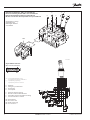
Trykindstilling
Pressure setting
Druckeinstellung
Réglage de pression
PVP,
Indstilling af LS sikkerhedsventil
LS relief valve setting
Einstellung des LS Sicherheitsventils
Réglage vanne de décharge LS
8[0.31]
3[0.12]
360° ~ 130 bar
[360° ~ 1900 psi]
35 Nm
[310 lbf•in]
3 Nm
[27 lbf•in]
P
MA
LS
6[0.24]
6[0.24]
3[0.12]
3[0.12]
V310102.A
PVB,
Indstilling af LS sikkerhedsventil
LS relief valve setting
Einstellung des LS Sicherheitsventils
Réglage vanne de décharge LS
360° ~ 130 bar
[360° ~ 1900 psi]
3 Nm
[27 lbf•in]
LX
T
PP
3[0.12]
6[.24]
8[0.31]
3[0.12]
6[.24]
3[0.12]
[510 lbf•in]
35 Nm
V310094.A

8 520L0526 • Rev CC • Feb 2015 © Danfoss A/S, 2015-02
PVEO
PVEH
B
A
B
A
P A
P B
MA
P
S
V310158.A
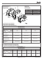
Elektrisk ventilaktuator, PVE serie 4 til PVG 120
Electrical actuating module PVE series 4 for PVG 120
Elektrische Betätigung, PVE Serie 4 für PVG 120
Module servomoteur électrique PVE série 4 pour PVG 120
Oliestrømmens retning
Oil ow direction
Richtung des Ölstroms
Sens du débit
U
DC
= Forsyningsspænding/Supply voltage
Versorgungsspannung/Tension d'alimentation
U
S
= Signalspænding/Signal voltage
Signalspannung/Tension de commande
E: Nødstop
E: Emergency circuit braker
E: Notschalter
E: Interrupteur
F: Udtag fra fejlovervågning
F: Branch circuit for fault indication
F: Anzapfung von der Fehlerüberwachung
F: Prise du surveillance défaut
NC: Ikke tilsluttet
NC: Not connected
NC: Nicht eingeloggt
NC: Pas connecté
25 pin SUB-D connector
(MIL-C-24308 /DIN 41652)
Push/Dir.sw.4B
Push/Dir.sw.4A
Push/Dir.sw.3B
Push/Dir.sw.3A
PVEM
PVEH/A/S
DC
V310116.A
P4B
1
PVEO
3
2
1
3
1
2
3
1
2
2
3
S2
UU
S1
P3BP3A P4A
Prop 2
Function
Prop 1
E
U
-
+
U+
+
-
DC
Neut.sw.
U
+
+
U
-
U
U- (GND)
19
Pin no.
7
8
6
3, 15, 16
1, 2, 14
10
21
20
22
F
NC
NC

© Danfoss A/S, 2015-02 520L0526 • Rev CC • Feb 2015 9
Hirschmann-version
on/o
Hirschmann-version
proportional
Function Signal voltage (U
S
)
Neutral U
S
(pin 2)
= 0.5 • U
DC
Q: P -> A U
S
(pin 2) = (0.5 -> 0.25) • U
DC
Q: P -> B U
S
(pin 2) = (0.5 -> 0.75) • U
DC
Function
Signal voltage (A or B)
A (pin 1) B (pin 2)
Neutral 0 0
Q: P -> A U
DC
0
Q: P -> B 0 U
DC
AMP-stik til PVE serie 4
AMP connec tor for PVE series 4
AMP-Stecker für PVE Serie 4
Kit AMP pour PVE serie 4
Pos. Description Qty. AMP Code no.
Danfoss
Code no.
Danfoss
Code no with
4 mm cable
1 Wire sealing (blue) 4* 828904-1
157B4992
min. 5 pcs
157B4994
min. 5 pcs.
2 Blind plug (transparent) 1 828922-1
3 JPT contact (loose piece) 4* 929930-1
4 JPT housing keying B (gray) 1 2-967059-1
JPT = AMP Junior Power Timer

10 520L0526 • Rev CC • Feb 2015 © Danfoss A/S, 2015-02
AMP-version on/o
Function Signal voltage (U
S
)
Neutral U
S
(pin 1)
= 0.5 • U
DC
Q: P -> A U
S
(pin 1) = (0.5 -> 0.25) • U
DC
Q: P -> B U
S
(pin 1) = (0.5 -> 0.75) • U
DC
Function
Signal voltage (A or B)
A (pin 1) B (pin 2)
Neutral 0 0
Q: P -> A U
DC
0
Q: P -> B 0 U
DC
AMP-version
proportional
Kabel med stik
Cable with connector
Kabel mit Stecker
Câble avec connecteur
PVE-funktion (gråt stik)
PVE-function (grey connector)
PVE-Funktion (Grauer Stecker)
PVE-Fonction (Support gris)
Pin 1 Hvid, White, Weiß, Blance
Pin 2 Blå, Blue, Blau, Bleu
Pin 3 Gul, Yellow, Gelb, Jaune
Pin 4 Rød, Red, Rot, Rouge
Pin 4 F
Pin 3 U-
Pin 2 U+
Pin 1 Us
Code: 157B4994
(min. 5 pcs.)

© Danfoss A/S, 2015-02 520L0526 • Rev CC • Feb 2015 11
PVE fejlovervågning
PVE fault monitoring
PVE Fehlerüberwachung
PVE Surveillance de défat
Normal
Grøn A: Eksternt relæ
Green A: External relay
Grün A: Externes Relais
Vert A: Relais externe
B: Magnetventil
B: Solenoid valve
B: Magnetventil
B: Electrodistributeur
Fejl / Fault / Fehler / Défaut
Rød A: Eksternt relæ
Red A: External relay
Rot A: Externes Relais
Rouge A: Relais externe
B: Magnetventil
B: Solenoid valve
B: Magnetventil
B: Electrodistributeur

12 520L0526 • Rev CC • Feb 2015 © Danfoss A/S, 2015-02
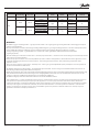
Type
Fault
monitoring
Delay before
error out
Error mode
Error output
status
Fault output
on PVE
1)
LED light
Memory (reset
needed)
PVEO
No fault
monitoring
- - - - - -
PVEH
Active 500 ms
No fault Low < 2 V Green -
Input signal faults
High ∼U
DC
Flashing red
YesTransducer (LVDT)
Constant red
Close loop fault
Passive 250 ms
No fault Low < 2 V Green -
Input signal faults
High ~U
DC
Flashing red
NoTransducer (LVDT)
Constant red
Close loop fault
1)
Measured between fault output pin and ground
WWARNING
Alle mærker og typer af retningsventiler – også proportional ventiler – kan svigte og forårsage alvorlig skade. Det er derfor vigtigt at analysere
maskinen i alle enkeltheder.
Da proportionalventiler anvendes under mange forskellige driftsbetingelser og i mange forskellige maskiner, er det alene maskinproducentens
ansvar at træe det endelige produktvalg og sikre at samtlige maskinens krav til ydelse, sikkerhed og advarsler er opfyldt.
Ved valg af reguleringssystem – og sikkerhedsniveau – kan man f.eks. støtte sig til EN954-1 (sikkerhedsrelaterede bestanddele i
reguleringssystemet).
All marks and all types of directional control valves – inclusive proportional valves – can fail and cause serious damage. It is therefore important to
analyse all aspects of the application.
Because the proportional valves are used in many dierent operation conditions and applications, the manufacturer of the application is alone
responsible for making the nal selection of the products – and assuring that all performance, safety and warning requirements of the
application are met.
The process of choosing the control system – and safety level – could e.g. be governed by EN 954-1 (Safety related parts of control system). See
also Technical information for PVE series 4.
Alle Fabrikate und Typen von Wegeventilen – einschließlich Proportionalventile – können versagen und schlimme Unfälle verursachen. Es ist
daher wichtig, die Anwendung in allen Details zu analysieren.
Weil Proportionalventile unter vielen unterschiedlichen Arbeitsbedingungen und in vielen verschiedenen Anwendungen benutzt werden, trägt
allein der Maschinenhersteller die Verantwortung für seine endgültige Wahl von Produkt, und er ist ebenfalls dafür verantwortlich, dass alle
Leistungs-, Sicherheits- und Warnungsanforderungen an seine Maschine erfüllt sind.
Zur Wahl vom Reglersystem und Sicherheitsniveau kann man sich z.B. auf EN954-1 stützen.
Tous les distributeurs - y compris les distributeurs proportionnels - peuvent tomber en panne et entraîner de sérieux dommages. C’est la raison
pour laquelle il est important d’analyser chaque aspect de l’application. Les vannes proportionnelles étant utilisées dans de nombreuses
conditions d’exploitation et applications diérentes, le fabricant de l’application porte l’entière responsabilité de la sélection nale des produits
et du respect des exigences en matière de rendement, de sécurité et d’avertissement. Le choix du système de commande – et du niveau de
sécurité – peut être fait par exemple sur la base de la norme EN 954-1 (parties du système de commande relatives à la sécurité). Se reporter
également à Information technique pour PVE série 4.
-
 1
1
-
 2
2
-
 3
3
-
 4
4
-
 5
5
-
 6
6
-
 7
7
-
 8
8
-
 9
9
-
 10
10
-
 11
11
-
 12
12


in anderen Sprachen
- English: Danfoss PVG 120 Installation guide
- français: Danfoss PVG 120 Guide d'installation
- dansk: Danfoss PVG 120 Installationsvejledning
Verwandte Artikel
-
Danfoss PVG 120 Installationsanleitung
-
Danfoss PVG 100 Installationsanleitung
-
-
Danfoss PVG 16 Installationsanleitung
-
-
-
-
Danfoss PVHC Benutzerhandbuch
-
-