
Installation Guide
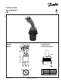
Joystick Prof 1
CIP
© Danfoss, 2014-03 L1317817 • Rev AB • Mar 2014 1
162R9003
162R9003
Montering Positionering af greb
Mounting Positioning of grip
Montage Positionierung des griffes
Montage Positionnement de la poignée
H
Nøglevidde Moment
Across flats torque
Schlüsselweite Anzungsmoment
Surplats Couple de serrage
2.5 2.1 Nm

2 L1317817 • Rev AB • Mar 2014 © Danfoss, 2014-03
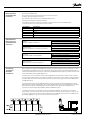
Terminering
Termination
Anschluß
Terminaison
Det er vigtigt at der i begge ender af CAN bussen foretages en terminering. Termineringen indeholder en 120 Ω
modstand. Denne terminering er placeret i Prof 1 CIP. For at gøre dette simpelt, er ben 1 CAN-forbundet med en
120 Ω modstand. Derfor kan man, hvis Prof 1 CIP er den sidste CAN-komponent på bussen, terminere ved at sætte
en lus mellem CAN+ (ben 4) og CAN-Term (ben 1).
It is important to ensure termination at both ends of the CAN-bus. The termination contains a 120 Ω resistance
and is contained in Prof 1 CIP. To keep it simple, pin 16 CAN- is connected to a 120 Ω resistance. If Prof 1 CIP is the
last CAN component on the bus the termination can be ensured by incorporating a shunt between CAN+ (pin 4)
and CAN-Term (pin 1).
Es ist wichtig, daß beide Seiten vom CAN-Bus-Kabel angeschlossen sind. Dieser Anschluß umfaßt einen 120 Ω
Widerstand und ist im Prof 1 CIP enthalten. Es ist einfach Stift 16 CAN- mit einem 120 Ω Widerstand zu verbinden.
Wenn daher Prof 1 CIP die letzte CAN Komponente an dem Bus ist, kann der Bus mit diesem Widerstand
abgeschlossen werden. Verbindung mit CAN+ (Stift 4) und CAN-Term (Stift 1).
Il est important de réaliser une terminaison aux deux extrémités du CAN bus. La terminaison est constituée
d’une résistance de 120 Ω qui est incluse dans le Prof 1 CIP. La borne numéro 16 du connecteur est reliée à cette
résistance de 120 Ω. Si le Prof 1 CIP est le dernier élément du bus, il suffit d’insérer un shunt entre le CAN+ (borne
4) et le CAN_TERM (borne 1) pour connecter la résistance de terminaison.
Stikforbindelser
Plug connection
Anschlußstecker
Connexion
Stiktype
Kun del nr. 282404-1 medleveres
AMP del nr. 282404-1, hanstik
AMP del nr. 282403-1, hunstik
Tilhørende pakninger og propper
Connector type
Only part N° 282404-11 is included in the delivery
AMP part N° 282404-1, male
AMP part N° 282403-1, female
Associated seals and plugs
Steckertyp
Nur Teil Nr. 282404-1 wird mitgeliefert
AMP Teil Nr. 282404-1, Stecker
AMP Teil Nr. 282403-1, Steckbuchse
Dazugehörende Dichtungen und Stopfen
Type connecteur
Seulement livré avec élément 1282404-1
Connecteur mâle AMP N°. 282404-1
Connecteur femelle AMP N°. 282403-1
Joints et vis associées
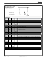
Der er 2 stik på joysticket, og ved forbindelse er det underordnet hvilket stik der bliver forbundet.
På et stik er der følgende ben:
The joystick has two plugs, either of which can be used for connection.
Each plug offers the following pin function:
Der Joystick hat zwei Stecker, wovon jeder benytzt werden kann.
Jeder Stecker verfügt über folgende Steckerstifte:
Le manipulateur posséde 2 connecteurs identiques, que peuvent être connecteur indifféremment
Les deux connecteurs sont composés des contacts soivants:
Pin-number Description
1 CAN_TERM
2 Udc
3 Ground
4 CAN+
5 CAN-
Stikforbindelser
Plug connection
Anschlußstecker
Connexion

© Danfoss, 2014-03 L1317817 • Rev AB • Mar 2014 3
Mode settings via the dip switch
Mode settings via the dip switch
Modus-Wahl mit DIP-Schalter
Réglage des sélecteurs
Dip switch placering
Location of the dip switch
Plazierung vom Dip-Schalter
Position des sélecteurs
Dip switch nummer
1 2 3 4 Mode
Closed x x x Joystick arbejder som CAN open slave
Open x x x Joystick arbejder som CAN open minimum master
x Closed x x Baudrate og Node Id som Object Dictionary og justeret via software
x Open x x Default Baudrate og Node Id
x x Closed x -
x x Open x -
x x x Closed -
x x x Open -
Dip switch No.
1 2 3 4 Mode
Closed x x x Joystick works as CAN open slave
Open x x x Joystickworks as CAN open minimum master
x Closed x x Baudrate and Node Id as per Object Dictionary and adjusted via the software
x Open x x Default Baudrate and Node Id
x x Closed x -
x x Open x -
x x x Closed -
x x x Open -
Dip Switch Nummer
1 2 3 4 Mode
Closed x x x Joystick arbeitet als CAN open Slave
Open x x x Joystick arbeitet als CAN open Minimum Master
x Closed x x Baudrate und Bus-adresse gemäß Object Dictionary und mittels der Software eingestellt
x Open x x Standard Baudrate und Bus-adresse
x x Closed x -
x x Open x -
x x x Closed -
x x x Open -
N° du sélecteur
1 2 3 4 Mode
Closed x x x Le manipulateur fonctionne en mode esclave CAN Open
Open x x x Le manipulateur fonctionne en mode maître CAN Open
x Closed x x Débit de communication et ID noeuds définis par logiciel
x Open x x Débit de communication et numéro d’identité standard
x x Closed x -
x x Open x -
x x x Closed -
x x x Open -

© Danfoss, 2014-03 L1317817 • Rev AB • Mar 2014 4
Strømforsyning
Forsyningsspænding U
dc
10 - 30 V DC
Maks. forsyningsspænding 36 V DC
Maks. pulsation 5%
Bemærk: Prof 1 CIP kan i modsætning til analoge joystick f.eks. Prof 1 tilsluttes batteriet direkte og behøver derfor ikke at have
forsyningsspænding fra PVE’erne.
Tekniske data
Technical data
Technische Daten
Caractéristiques
Techniques
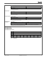
Prof 1 CIP dataformat
Prof 1 CIP data format
Prof 1 CIP Datenformat
Prof 1 CIP Format des données
SIGN = + / -
MSB = Most significant bit
LSB = Least significant bit
Power supply
Supply voltage U
dc
10 - 30 V DC
Max supply voltage 36 V DC
Max ripple 5%
Note: Contrary to analogue joysticks (such as Prof 1) PROF 1 CIP can be connected direct to the battery and does not need supply
voltage directly from the PVE’s.
Stromversorgung
Versorgungsspannung U
dc
10 - 30 V DC
Max Versorgungsspannung 36 V DC
Max Welligkeit 5%
Bemerkung: Im Gegensatz su analogen Joysticks (wie Prof 1) kann PROF 1 CIP direkt mit der Batterie verbunden werden und braucht
also keine Versorgungsspannung aus den PVE’s.
Alimentation
Tension d’alimentation U
dc
10 - 30 V DC
Tension maximale 36 V DC
Ondulation maximale 5%
Nb: Le Prof 1 CIP peut, contrairement aus manipulateurs Prof 1 analogiques, ětre relié directement à une source d’alimentation
électrique et ne cécessite donc pas une alimentation via les PVE.
1 byte SIGN----MSB --------------------------------------------------------Prop1-----------------------------------------------------
2 byte SIGN----MSB --------------------------------------------------------Prop2-----------------------------------------------------
3 byte SIGN----MSB --------------------------------------------------------Prop3-----------------------------------------------------
4 byte SIGN----MSB --------------------------------------------------------Prop4----------------------------------------------------
5 byte rest_Prop4 - LSB rest_Prop3 - LSB rest_Prop2 - LSB
rest_Prop1 - LSB
6 byte Push 8 Push 7 Push 6
Push 5 Push 4B Push 4A Push 3B Push 3A
8 bit 7 bit 6 bit
5 bit 4 bit 3 bit 2 bit 1 bit
-
 1
1
-
 2
2
-
 3
3
-
 4
4


Danfoss PROF1 Installationsanleitung
- Typ
- Installationsanleitung
- Dieses Handbuch eignet sich auch für
in anderen Sprachen
- English: Danfoss PROF1 Installation guide
- français: Danfoss PROF1 Guide d'installation
- dansk: Danfoss PROF1 Installationsvejledning
Verwandte Artikel
Andere Dokumente
-
WAGO DeviceNet Feldbuskoppler Benutzerhandbuch
-
-
 TR-Electronic LMP-30 Installationsanleitung
-
AVENTICS Bus Coupler AES/Valve Driver AV DeviceNet Benutzerhandbuch
-
Baumer GBMMW Bedienungsanleitung
-
Baumer GK473 Bedienungsanleitung
-
-
-
