
DE
EN
Operating instructions
Betriebsanleitung
Dual dierential pressure sensor, model A2G-52
Doppelter Dierenzdrucksensor, Typ A2G-52
Model A2G-52

2
40414616.01 02/2018 EN/DE
WIKA operating instructions model A2G-52
DE
EN
Operating instructions model A2G-52 Page 3 - 30
Betriebsanleitung Typ A2G-52 Seite 31 - 58
© 02/2018 WIKA Alexander Wiegand SE & Co. KG
All rights reserved. / Alle Rechte vorbehalten.
WIKA
®
is a registered trademark in various countries.
WIKA
®
ist eine geschützte Marke in verschiedenen Ländern.
Prior to starting any work, read the operating instructions!
Keep for later use!
Vor Beginn aller Arbeiten Betriebsanleitung lesen!
Zum späteren Gebrauch aufbewahren!

EN
WIKA operating instructions model A2G-52
40414616.01 02/2018 EN/DE
3
Contents
Contents
1. General information 4
2. Design and function 5
3. Safety 6
4. Transport, packaging and storage 11
5. Commissioning, operation 12
6. Menu navigation 21
7. Maintenance and cleaning 25
8. Dismounting, return and disposal 26
9. Specications 29
10. Accessories 30

EN
40414616.01 02/2018 EN/DE
4 WIKA operating instructions model A2G-52
1. General information
1. General information
■
The dierential pressure sensor described in the operating
instructions has been manufactured using state-of-the-art technology.
All components are subject to stringent quality and environmental
criteria during production. Our management systems are certied to
ISO 9001 and ISO 14001.
■
These operating instructions contain important information on
handling the instrument. Working safely requires that all safety
instructions and work instructions are observed.
■
Observe the relevant local accident prevention regulations and
general safety regulations for the instrument's range of use.
■
The operating instructions are part of the product and must be kept
in the immediate vicinity of the instrument and readily accessible to
skilled personnel at any time. Pass the operating instructions on to the
next operator or owner of the instrument.
■
Skilled personnel must have carefully read and understood the
operating instructions prior to beginning any work.
■
The general terms and conditions contained in the sales
documentation shall apply.
■
Subject to technical modications.
■
Further information:
- Internet address: www.wika.de / www.wika.com
www.air2guide.com
- Relevant data sheet: PE 88.03

EN
WIKA operating instructions model A2G-52
40414616.01 02/2018 EN/DE
5
2. Design and function
2. Design and function
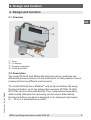
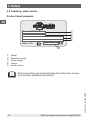
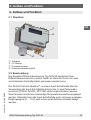
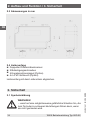
2.1 Overview
Case
LC display
Process connection
Cable gland M16
2.2 Description
The model A2G-52 dual dierential pressure sensor combines two
dierential pressure sensors in one instrument, so that pressure can be
measured from two dierent control points.
The model A2G-52 has a Modbus
and an input interface. By using
the input interface, up to two temperature sensors (Pt1000, Ni1000,
NTC10K) can be connected directly. Thus, temperature transmitters
which would otherwise be necessary can be saved. Alternatively,
the input interface can also be assigned to an analogue input signal
(0 ... 10 V) or a potential-free contact.

EN
40414616.01 02/2018 EN/DE
6 WIKA operating instructions model A2G-52
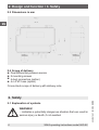
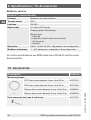
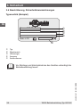
2.3 Dimensions in mm
2.4 Scope of delivery
■
Dual dierential pressure sensor
■
2 mounting screws
■
4 duct connectors (option)
■
4 m PVC hose (option)
Cross-check scope of delivery with delivery note.
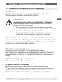
3. Safety
3.1 Explanation of symbols
WARNING!
... indicates a potentially dangerous situation that can result in
serious injury or death, if not avoided.
2. Design and function / 3. Safety

EN
WIKA operating instructions model A2G-52
40414616.01 02/2018 EN/DE
7
CAUTION!
... indicates a potentially dangerous situation that can result in
light injuries or damage to property or the environment, if not
avoided.
DANGER!
... identies hazards caused by electrical power. Should the
safety instructions not be observed, there is a risk of serious
or fatal injury.
WARNING!
... indicates a potentially dangerous situation that can result in
burns, caused by hot surfaces or liquids, if not avoided.
Information
... points out useful tips, recommendations and information for
ecient and trouble-free operation.
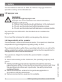
3.2 Intended use
This dual dierential pressure sensor is used for measuring dierential
pressures of air and other non-inammable and non-aggressive gases in
ventilation and air-conditioning applications.
This instrument is not permitted to be used in hazardous areas!
The instrument has been designed and built solely for the intended use
described here, and may only be used accordingly.
The technical specications contained in these operating instructions
must be observed. Improper handling or operation of the instrument
outside of its technical specications requires the instrument to be taken
out of service immediately and inspected by an authorised WIKA service
engineer.
3. Safety

EN
40414616.01 02/2018 EN/DE
8 WIKA operating instructions model A2G-52
The manufacturer shall not be liable for claims of any type based on
operation contrary to the intended use.
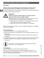
3.3 Improper use
WARNING!
Injuries through improper use
Improper use of the instrument can lead to hazardous
situations and injuries.
▶
Refrain from unauthorised modications to the instrument.
▶
Do not use the instrument within hazardous areas.
▶
Do not use the instrument with abrasive or viscous media.
Any use beyond or dierent to the intended use is considered as
improper use.
Do not use this instrument in safety or emergency stop devices.
3.4 Responsibility of the operator
The instrument is used in the industrial sector. The operator is therefore
responsible for legal obligations regarding safety at work.
The safety instructions within these operating instructions, as well as the
safety, accident prevention and environmental protection regulations for
the application area must be maintained.
The operator is obliged to maintain the product label in a legible
condition.
To ensure safe working on the instrument, the operating company must
ensure
■
that the operating personnel are regularly instructed in all topics
regarding work safety, rst aid and environmental protection and know
the operating instructions and in particular, the safety instructions
contained therein.
■
that the instrument is suitable for the particular application in
accordance with its intended use.
■
that personal protective equipment is available.
3. Safety

EN
WIKA operating instructions model A2G-52
40414616.01 02/2018 EN/DE
9
3.5 Personnel qualication
WARNING!
Risk of injury should qualication be insucient
Improper handling can result in considerable injury and
damage to equipment.
▶
The activities described in these operating instructions
may only be carried out by skilled personnel who have the
qualications described below.
Skilled electrical personnel
Skilled electrical personnel are understood to be personnel who,
based on their technical training, know-how and experience as well
as their knowledge of country-specic regulations, current standards
and directives, are capable of carrying out work on electrical systems
and independently recognising and avoiding potential hazards. The
skilled electrical personnel have been specically trained for the work
environment they are working in and know the relevant standards and
regulations. The skilled electrical personnel must comply with current
legal accident prevention regulations.
Operating personnel
The personnel trained by the operator are understood to be personnel
who, based on their education, knowledge and experience, are capable
of carrying out the work described and independently recognising
potential hazards.
Special operating conditions require further appropriate knowledge, e.g.
of aggressive media.
3. Safety

EN
40414616.01 02/2018 EN/DE
10 WIKA operating instructions model A2G-52
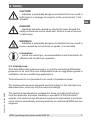
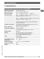
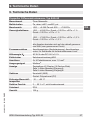
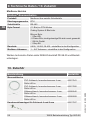
Type:
A2G-50
Range:
-250 ... +250 Pa
Output:
0 ... 10 V / 4 ... 20 mA
Supply: DC 24 V / AC 24 V ±10 % < 1 W
Made in EU E-Nr. 66209848
3.6 Labelling, safety marks
Product label (example)
3. Safety
Model
Measuring range
Power supply
Output
Serial number
Before mounting and commissioning the instrument, ensure
you read the operating instructions!

EN
WIKA operating instructions model A2G-52
40414616.01 02/2018 EN/DE
11
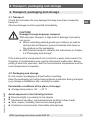
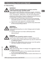
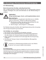
4. Transport, packaging and storage
4.1 Transport
Check the instrument for any damage that may have been caused by
transport.
Obvious damage must be reported immediately.
CAUTION!
Damage through improper transport
With improper transport, a high level of damage to property
can occur.
▶
When unloading packed goods upon delivery as well as
during internal transport, proceed carefully and observe
the symbols on the packaging.
▶
With internal transport, observe the instructions in chapter
4.2 “Packaging and storage”.
If the instrument is transported from a cold into a warm environment, the
formation of condensation may result in instrument malfunction. Before
putting it back into operation, wait for the instrument temperature and the
room temperature to equalise.
4.2 Packaging and storage
Do not remove packaging until just before mounting.
Keep the packaging as it will provide optimum protection during transport
(e.g. change in installation site, sending for repair).
Permissible conditions at the place of storage:
■
Storage temperature: -20 ... +70 °C
Avoid exposure to the following factors:
■
Direct sunlight or proximity to hot objects
■
Mechanical vibration, mechanical shock (putting it down hard)
■
Soot, vapour, humidity, dust and corrosive gases
■
Hazardous environments, ammable atmospheres
4. Transport, packaging and storage

EN
40414616.01 02/2018 EN/DE
12 WIKA operating instructions model A2G-52
4. Transport ... / 5. Commissioning, operation
Store the instrument in its original packaging in a location that fulls the
conditions listed above. If the original packaging is not available, pack
and store the instrument as described below:
1. Wrap the instrument in an antistatic plastic lm.
2. Place the instrument, along with the shock-absorbent material, in the
packaging.
3. If stored for a prolonged period of time (more than 30 days), place a
bag containing a desiccant inside the packaging.
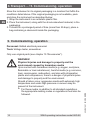
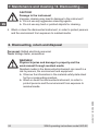
5. Commissioning, operation
Personnel: Skilled electrical personnel
Tools: Voltage tester, screwdriver
Only use original parts (see chapter 10 “Accessories”).
WARNING!
Physical injuries and damage to property and the
environment caused by hazardous media
Upon contact with hazardous media (e.g. oxygen, acetylene,
ammable or toxic substances), harmful media (e.g. corrosive,
toxic, carcinogenic, radioactive), and also with refrigeration
plants and compressors, there is a danger of physical injuries
and damage to property and the environment.
Should a failure occur, aggressive media with extremely high
temperature and under high pressure or vacuum may be
present at the instrument.
▶
For these media, in addition to all standard regulations,
the appropriate existing codes or regulations must also be
followed.

EN
WIKA operating instructions model A2G-52
40414616.01 02/2018 EN/DE
13
CAUTION!
Damage to the instrument
When working on open electric circuits (printed circuit boards)
there is a risk of damaging sensitive electronic components
through electrostatic discharge.
▶
The correct use of grounded working surfaces and
personal armbands is required.
DANGER!
Danger to life caused by electric current
Upon contact with live parts, there is a direct danger to life.
▶
The instrument may only be installed and mounted by
skilled personnel.
▶
Operation using a defective power supply unit (e.g. short
circuit from the mains voltage to the output voltage) can
result in life-threatening voltages at the instrument!
1. Instrument xing at the desired mounting location
(see chapter 5.1 “Instrument mounting”)
2. Opening the instrument cover, feeding the connection cable through
the cable gland and connecting the wires to the terminal block (see
chapter 5.3 “Electrical mounting”)
3. The instrument is now ready for conguration (see chapter 5.4
“Conguration”)
5. Commissioning, operation

EN
40414616.01 02/2018 EN/DE
14 WIKA operating instructions model A2G-52
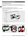
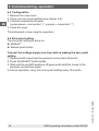
5.1 Instrument mounting
Screw the dierential pressure transmitter onto a suitable vertical
surface and x it horizontally with the mounting screws delivered with the
instrument.
1. Select a mounting location (duct, wall, panel).
2. Remove the case cover and use the screw holes as a template.
3. Mount with suitable screws.
Instrument xing
Instrument orientation
5. Commissioning, operation

EN
WIKA operating instructions model A2G-52
40414616.01 02/2018 EN/DE
15
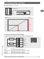
+
+
+
+
-
-
+
-
-
+
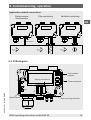
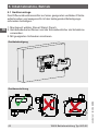
Application-related connections
Static pressure
measurement
Filter monitoring Ventilator monitoring
5. Commissioning, operation
- not
connected
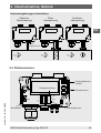
5.2 PCB diagram
LEDs
A
B
24V
GND
GND
GND
Down
Menu buttons
Rack-mounting terminals
Display connections
Pressure sensors
Input sockets -
jumpers
Output Input
Input 2
Input 1
Select
Up

EN
40414616.01 02/2018 EN/DE
16 WIKA operating instructions model A2G-52
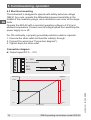
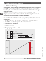
5.3 Electrical mounting
The instrument is designed to operate with safety extra-low voltage
(SELV). As a rule, operate the dierential pressure transmitter in the
middle of the measuring range, since deviations can occur at the range
limits.
Operate the A2G-50 with a constant operating voltage (±0.2 V) and
ambient temperature. Prevent current/voltage spikes from switching the
power supply on or o.
For CE conformity, a properly grounded protective cable is required.
1. Unscrew the strain relief and feed the cable(s) through.
2. Connect the wires (see “Connection diagram”).
3. Tighten down the strain relief.
Connection diagram
■
Output signal DC 0 ... 10 V
V
A
Pressure P Signal [U]
100 % 10.0 V
50 % 5.0 V
0 % 0.0 V
Time axis t [s]
Pressure P Signal [I]
100 % 20.0 mA
50 % 12.0 mA
0 % 4.0 mA
Time axis t [s]
0 ... 10 V
not connected
24 V
GND
Power supply
AC/DC 24 V
5. Commissioning, operation

EN
WIKA operating instructions model A2G-52
40414616.01 02/2018 EN/DE
17
5. Commissioning, operation
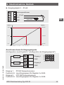
■
Output signal 4 ... 20 mA
Connection diagram for input signals
(conguration see chapter 5.7 “Input signal conguration”)
Input 1: Pt1000 temperature sensor
Function 04: Read input value for register 3 x 0005
Input 2: NTC10K temperature sensor
Function 04: Read input value for register 3 x 0008
Pressure P Signal [U]
100 % 10.0 V
50 % 5.0 V
0 % 0.0 V
Time axis t [s]
Pressure P Signal [I]
100 % 20.0 mA
50 % 12.0 mA
0 % 4.0 mA
Time axis t [s]
V
A
Power supply
AC/DC 24 V
not connected
4 ... 20 mA
24 V
GND
Pt1000
J1
J2
J3
NTC10k
Input 1
GND
Input 2
GND
Input 2Input 1

EN
40414616.01 02/2018 EN/DE
18 WIKA operating instructions model A2G-52
5. Commissioning, operation
5.4 Conguration
1. Remove the case cover.
2. Carry out a zero point setting (see chapter 5.5).
3. Connect measurement hoses.
(overpressure = connection “+”, vacuum = connection “-”)
4. Close the cover.
The instrument is now ready for operation.
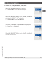
5.5 Zero point setting
The zero point setting is done via
■
Modbus
®
■
Manual push-button
Connect the voltage supply one hour before making the zero point
setting
1. Remove both hoses from the pressure connections ⊕ and ⊖.
2. Press the SELECT button briey.
3. Wait until the red LED switches o again and install the hoses to the
pressure connections again.
In normal operation, carry out a zero point setting every 12 months.

EN
WIKA operating instructions model A2G-52
40414616.01 02/2018 EN/DE
19
5. Commissioning, operation
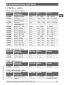
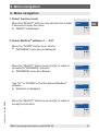
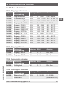
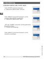
5.6 Modbus
register
FC04 - Read input register
Register Parameter
description
Data type Value Display
3x0001 Program version 16 bit 0 ... 1,000 0.00 ... 99.00
3x0002 Pressure
measurement A
16 bit -250 ... 2,500 -250 ... 2,500 (Pa)
3x0003 Pressure
measurement B
16 bit -250 ... 2,500 -250 ... 2,500 (Pa)
3x0004 Input 1: 0 ... 10 V 16 bit 0 ... 1,000 0 ... 100 %
3x0005 Input 1: Pt1000 16 bit 500 ... 500 -50 ... +50 °C
3x0006 Input 1: Ni1000 16 bit -500 ... 500 -50 ... +50 °C
3x0007 Input 1: Ni1000-LG 16 bit -500 ... 500 -50 ... +50 °C
3x0008 Input 1: NTC10k 16 bit -500 ... 500 -50 ... +50 °C
3x0009 Input 2: 0 ... 10 V 16 bit 0 ... 1,000 0 ... 100 %
3x0010 Input 2: Pt1000 16 bit -500 ... 500 -50 ... +50 °C
3x0011 Input 2: Ni1000 16 bit -500 ... 500 -50 ... +50 °C
3x0012 Input 2: Ni1000-L 16 bit -500 ... 500 -50 ... +50 °C
3x0013 Input 2: NTC10k 16 bit -500 ... 500 -50 ... +50 °C
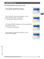
FC02 - Read input status
Register Parameter
description
Data type Value Display
1x0001 Input 1: BIN IN Bit 0 0 ... 1 On - O
1x0002 Input 2: BIN IN Bit 0 0 ... 1 On - O
FC05 - Write single coil
Register Parameter
description
Data type Value Display
0x0001 Zeroing Bit 0 0 ... 1 On - O
FC06 - Write single register
Register Parameter
description
Data type Value Display
4x0001 Beta value of NTC
resistor
16 bit 0 ... 30,000 0 ... 30,000
(standard 4,220)

EN
40414616.01 02/2018 EN/DE
20 WIKA operating instructions model A2G-52
5. Commissioning, operation
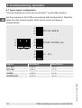
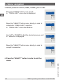
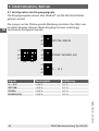
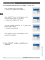
5.7 Input signal conguration
The input signals can be read over Modbus
®
via RS-485 interface.
Set the jumpers on the PCB in accordance with the illustration. Read the
value from the correct register. Both inputs can be congured
independently.
Signal Accuracy Resolution
0 ... 10 V < 0.5 % 0.1 %
NTC10K < 0.5 % 0.1 %
Pt1000 < 0.5 % 0.1 %
Ni1000/(-LG) < 0.5 % 0.1 %
J1
J2
J3
J1
J2
J3
J1
J2
J3
J1
J2
J3
NTC10k / BIN IN
Pt1000 / Ni10007(-LG)
0 ... 10 V
IN1
IN2
Seite wird geladen ...
Seite wird geladen ...
Seite wird geladen ...
Seite wird geladen ...
Seite wird geladen ...
Seite wird geladen ...
Seite wird geladen ...
Seite wird geladen ...
Seite wird geladen ...
Seite wird geladen ...
Seite wird geladen ...
Seite wird geladen ...
Seite wird geladen ...
Seite wird geladen ...
Seite wird geladen ...
Seite wird geladen ...
Seite wird geladen ...
Seite wird geladen ...
Seite wird geladen ...
Seite wird geladen ...
Seite wird geladen ...
Seite wird geladen ...
Seite wird geladen ...
Seite wird geladen ...
Seite wird geladen ...
Seite wird geladen ...
Seite wird geladen ...
Seite wird geladen ...
Seite wird geladen ...
Seite wird geladen ...
Seite wird geladen ...
Seite wird geladen ...
Seite wird geladen ...
Seite wird geladen ...
Seite wird geladen ...
Seite wird geladen ...
Seite wird geladen ...
Seite wird geladen ...
Seite wird geladen ...
Seite wird geladen ...
-
 1
1
-
 2
2
-
 3
3
-
 4
4
-
 5
5
-
 6
6
-
 7
7
-
 8
8
-
 9
9
-
 10
10
-
 11
11
-
 12
12
-
 13
13
-
 14
14
-
 15
15
-
 16
16
-
 17
17
-
 18
18
-
 19
19
-
 20
20
-
 21
21
-
 22
22
-
 23
23
-
 24
24
-
 25
25
-
 26
26
-
 27
27
-
 28
28
-
 29
29
-
 30
30
-
 31
31
-
 32
32
-
 33
33
-
 34
34
-
 35
35
-
 36
36
-
 37
37
-
 38
38
-
 39
39
-
 40
40
-
 41
41
-
 42
42
-
 43
43
-
 44
44
-
 45
45
-
 46
46
-
 47
47
-
 48
48
-
 49
49
-
 50
50
-
 51
51
-
 52
52
-
 53
53
-
 54
54
-
 55
55
-
 56
56
-
 57
57
-
 58
58
-
 59
59
-
 60
60


in anderen Sprachen
- English: WIKA A2G-52 Operating instructions
Verwandte Artikel
-
WIKA A2G-100 Bedienungsanleitung
-
-
-
-
WIKA TF41 Bedienungsanleitung
-
-
-
-
-
