SystemAir NTC10k Installation Instructions Manual
- Typ
- Installation Instructions Manual

date: 24.04.2020 page 1 / 6
Systemair GmbH Germany [email protected] oder http://www.systemair.de/
Installation instructions
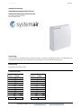
218834 Room temperature sensor NTC10k
Surface-mounted temperature sensor
Subject to technical alteration
Issue date: 24.04.2020 • A100
Application
Surface mounted room sensor for temperature measuring, with set point and fan stage adjustment, manual override for room and office
applications.
Name
218834 Room temperature sensor NTC10k
Technical Data
Temp. °C
NTC 10K
kOHM
Temp. °C
NTC 10k
kOHM
-50
667,83
50
3,60
-40
335,67
60
2,49
-30
176,68
70
1,75
-20
96,97
80
1,26
-10
55,30
90
0,92
0
32,65
100
0,68
10
19,90
110
0,51
20
12,49
120
0,39
25
10,00
130
0,30
30
8,08
140
0,23
40
5,32
150
0,18

date: 24.04.2020 page 2 / 6
Systemair GmbH Germany [email protected] oder http://www.systemair.de/
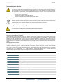
Security Advice - Caution
The installation and assembly of electrical equipment should only be performed by authorized personnel. Consider the precautions
when handling equipment that is sensitive to electrostatic charges.
The device is designed for installation in a flush-mounted box indoors The product should only be used for the intended application.
Unauthorised modifications are prohibited! The product must not be used in relation with any equipment that in case of a failure
may threaten, directly or indirectly, human health or life or result in danger to human beings, animals or assets. Ensure all power
is disconnected before installing. Do not connect to live/operating equipment.
Warning! Risk of electric shock due to live components within the enclosure, especially devices with mains
voltage supply (usually between 90..265 V).
Please comply with
Local laws, health & safety regulations, technical standards and regulations
Condition of the device at the time of installation, to ensure safe installation
This data sheet and installation manual
Notes on Disposal
As a component of a large-scale fixed installation, Systemair products are intended to be used permanently as part of a building
or a structure at a pre-defined and dedicated location, hence the Waste Electrical and Electronic Act (WEEE) is not applicable.
However, most of the products may contain valuable materials that should be recycled and not disposed of as domestic waste.
Please note the relevant regulations for local disposal.
Storage of the installation instructions
Read carefully before use and keep for future reference.
Remarks to Room Sensors
Location and Accuracy of Room Sensors
The room sensor should be mounted in a suitable location for measuring accurate room temperature. The accuracy of the temperature
measurement also depends directly on the temperature dynamics of the wall. It is important, that the back plate is completely flush to the wall so
that there is sufficient circulation of air through the vents in the cover, otherwise, deviations in temperature measurement will occur due to
uncontrolled air circulation. The temperature sensor should not be covered by furniture or other objects. Mounting next to doors (due to draught)
or windows (due to colder outside wall) should be avoided.
Surface and Flush Mounting
The measuring result is influenced by the thermal characteristics of the wall. A solid concrete wall responds to thermal fluctuations within a room
in a much slower than a light-weight structure wall. Room temperature sensors installed in flush-mounted boxes have a longer response time to
thermal variations. In extreme cases they detect the radiant heat of the wall even if the air temperature in the room is lower for example. The
quicker the dynamics of the wall (temperature acceptance of the wall) or the longer the selected inquiry interval of the temperature sensor is the
smaller the deviations limited in time are.
Technical Data
Measuring values
temperature
Output passive
passiv
e
NTC10k
Operating temperature
range
max. permissible operating temperature-35..+70 °C
Accuracy temperature
passiv
e
+-0,22K at 25°C
Sensor
passiv
e
2-Leiter (Standard)
Enclosure
PC, pure white similar to RAL9010
Protection
IP30 according to EN 60529
Cable entry
breaking points top/bottom, rear entry
Connection electrical
terminal block, max. 1,5 mm²
Ambient condition
max. 85% rH non-condensing
Mounting
flush mounted with standard EU box (Ø=60 mm)

date: 24.04.2020 page 3 / 6
Systemair GmbH Germany [email protected] oder http://www.systemair.de/
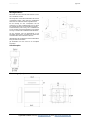
Mounting Advices
Make sure that the device is power-off, if you install it!
The device can be installed on a smooth wall surface or a
flush box. It should be selected a representative location for
the measuring medias. The use of deep installation boxes is
recommended due to the increased storage capacity for the
cabling.
Sunlight and drafts e.g. in conduit must be avoided so that
the measuring result is not distorted. If necessary, is the end
of the installation tube seal
(1) For wiring, the upper part of the base plate must be
solved. Base plate and upper part are connected with each
other by mounting clips.
(2) The installation of the base plate to the smooth wall
surface can be done with plugs and screws.
(3) Then, the device is placed on the base plate.
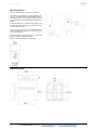
Dimensions (mm)

date: 24.04.2020 page 4 / 6
Systemair GmbH Germany [email protected] oder http://www.systemair.de/
Installationsanleitung
218834 Raumtemperaturfühler NTC10k
Aufputz-Raumtemperatursensor NTC10k
Technische Änderungen vorbehalten
Stand: 24.04.2020 • A100
Anwendung
Aufputz-Raumfühler zur Temperaturmessung in Wohnräumen, Büros etc. Ausgelegt zur Aufschaltung auf Regler- und Anzeigesysteme. Zum
Vorverdrahten am Montageort kann das Gehäuseunterteil mit Anschlussklemme vom Gehäuseoberteil demontiert werden.
Bezeichnung
218834 Raumtemperaturfühler NTC10k
Technische Daten
Temp. °C
NTC 10K
kOHM
Temp. °C
NTC 10k
kOHM
-50
667,83
50
3,60
-40
335,67
60
2,49
-30
176,68
70
1,75
-20
96,97
80
1,26
-10
55,30
90
0,92
0
32,65
100
0,68
10
19,90
110
0,51
20
12,49
120
0,39
25
10,00
130
0,30
30
8,08
140
0,23
40
5,32
150
0,18

date: 24.04.2020 page 5 / 6
Systemair GmbH Germany [email protected] oder http://www.systemair.de/
Sicherheitshinweis – Achtung
Der Einbau und die Montage elektrischer Geräte (Module) dürfen nur durch eine autorisierte Elektrofachkraft erfolgen.
Das Gerät ist nur für die bestimmungsgemäße Verwendung vorgesehen. Ein eigenmächtiger Umbau oder eine Veränderung ist
verboten! Die Module dürfen nicht in Verbindung mit Geräten benutzt werden, die direkt oder indirekt menschlichen, gesundheits-
oder lebenssichernden Zwecken dienen oder durch deren Betrieb Gefahren für Menschen, Tiere oder Sachwerte entstehen
können. Der Anschluss von Geräten mit Stromanschluss darf nur bei freigeschalteter Anschlussleitung erfolgen!
Ferner gelten
Gesetze, Normen und Vorschriften
Der Stand der Technik zum Zeitpunkt der Installation
Die technischen Daten sowie die Bedienungsanleitung des Gerätes
Entsorgungshinweis
Als Einzelkomponente von ortsfest installierten Anlagen fallen Systemair Produkte nicht unter das Elektro- und Elektronikgesetz
(ElektroG). Die meisten unserer Produkte enthalten wertvolle Rohstoffe und sollten deshalb nicht als Hausmüll entsorgt, sondern
einem geordneten Recycling zugeführt werden. Die örtlich gültige Entsorgungsregelung ist zu beachten.
Aufbewahrung der Bedienungsanleitung
WICHTIG!
Vor dem Gebrauch sorgfältig lesen und für späteres Nachschlagen aufbewahren.
Anmerkungen zu Raumfühlern
Platzierung und Genauigkeit von Raumfühlern
Die Genauigkeit der Temperaturmessung ist neben einem geeigneten repräsentativen, der Raumtemperatur entsprechenden Montageort auch
direkt von der Temperaturdynamik der Wand abhängig. Wichtig ist, dass bei Unterputzfühlern die Unterputzdose zur Wand hin komplett
geschlossen ist, damit eine Luftzirkulation nur durch die Öffnungen der Gehäuseabdeckung stattfinden kann. Anderenfalls kommt es zu
Abweichungen bei der Temperaturmessung durch unkontrollierte Luftströmungen. Zudem sollte der Temperaturfühler nicht durch Möbel oder
ähnliches abgedeckt sein. Des Weiteren sollte eine Montage in Türnähe (auftretende Zugluft) oder Fensternähe (kältere Außenwand) vermieden
werden.
Montage Aufputz versus Unterputz
Die Temperaturdynamik der Wand hat einen Einfluss auf das Messergebnis des Fühlers. Die verschiedenen Wandarten (Ziegel-, Beton-, Stell-,
Hohlwände) verhalten sich gegenüber Temperaturschwankungen unterschiedlich. So nimmt eine massive Betonwand viel langsamer die
Temperaturveränderung innerhalb eines Raumes wahr als Wände in Leichtbauweise. Wohnraumtemperaturfühler, die innerhalb einer UP-Dose
sitzen, haben eine größere Ansprechzeit bei Temperaturschwankungen. Sie detektieren im Extremfall die Strahlungswärme der Wand, obwohl die
Lufttemperatur im Raum bereits niedriger ist. Die zeitlich begrenzten Abweichungen verkleinern sich, je schneller die Dynamik
(Temperaturannahme) der Wand ist oder je länger das Abfrage-Intervall des Temperaturfühlers gewählt wird.
Technische Daten
Messgrößen
Temperatur
Ausgang passiv
passiv
NTC10k
Temperatureinsatzbereich
max. zulässige Arbeitstemperatur -35..+70 °C
Genauigkeit Temperatur passiv
+-0,22K bei 25°C
Sensor
passiv
2-Leiter (Standard)
Gehäuse Reinweiß ähnlich RAL9010
Schutzart IP30 gemäß DIN EN 60529
Kabeleinführung
Sollbruchstellen Oberseite/Unterseite, Öffnung Rückseite
Anschluss elektrisch
Schraubklemme, max. 1,5 mm²
Umgebungsbedingung
max. 85% nicht kondensierend
Montage
Aufputz auf Standard UP-Dose (Ø=60 mm)

date: 24.04.2020 page 6 / 6
Systemair GmbH Germany [email protected] oder http://www.systemair.de/
Montagehinweise
Bitte stellen Sie sicher, dass das Gerät stromfrei ist, wenn
Sie es installieren möchten!
Die Montage kann auf der ebenen Wandfläche oder auf einer
Unterputzdose erfolgen. Dabei sollte eine repräsentative
Stelle für die zu messenden Medien ausgewählt werden.
Bei der Montage auf einer Unterputzdose wird die
Verwendung von tiefen Installationsdosen wird auf Grund
des größeren Stauraumes für die Verkabelung empfohlen.
Sonneneinstrahlung sowie Luftzug z.B. im Installationsrohr
sind zu vermeiden, damit das Messergebnis nicht verfälscht
wird. Ggf. ist das Ende des Installationsrohres abzudichten.
(1) Zum Verdrahten muss das Geräteoberteil von der
Grundplatte gelöst werden. Grundplatte und Oberteil sind
mittels Rastnasen lösbar miteinander verbunden.
(2) Die Montage der Grundplatte auf der ebenen Wandfläche
erfolgt mit Dübel und Schrauben.
(3) Abschließend wird das Gerät auf die Grundplatte
aufgesteckt.
Anschlussplan
Abmessungen (mm)
-
 1
1
-
 2
2
-
 3
3
-
 4
4
-
 5
5
-
 6
6


SystemAir NTC10k Installation Instructions Manual
- Typ
- Installation Instructions Manual
in anderen Sprachen
- English: SystemAir NTC10k

