SystemAir TControl POD Bedienungsanleitung
- Typ
- Bedienungsanleitung

Systemair GmbH Germany [email protected] oder http://www.systemair.de/
Operation Manual
Subject to technical alteration
Issue date: 09.03.2018
Version 56.6.1
Application
Modern fan coil room thermostat to control fan coil units with EC fans. It is suitable for 2- and 4-pipe systems. It has 2 relays and
1 analogue output 0-10V (heating valve, cooling valve and EC fan). The device combines a modern design with a 2,5” LCD and a
touch-sensitive surface, 3 time program options each with 4 time periods options.
Desiignation
TControl POD 3s white
TControl Description: Temperature-Control
POD Name: POD
3s Fan control Art : 3s 3step Fan control
EC 0-10V Fan control
white Color: white or black

Page 2 / 27 Issue date: 09.03.2018
Systemair GmbH Germany [email protected] oder http://www.systemair.de/
Technical Data
Measuring values
temperature
Network technology
RS485 Modbus, baud rate 9.600, 19.200, 38.400 or 57.600, parity none (2 stopbits), even or odd (1 stopbit)
Output voltage
0..10 V, EC FAN control
Output switch contact
2x normally open contacts (heating/cooling), 240 V max. load 3 A
Power supply
85..260 V ~
Power consumption
max. 2 VA (260 V ~)
Measuring range temp
0..+50 °C
Accuracy temperature
±1 °C (typ. at 21 °C)
Inputs
input for NTC 10 K or change-over sensor
digital input for floating contact (230 V ~)
Control functions
setpoint adjustment +0..+50 °C
Display
LCD 60x44 mm, 240x160 px, white backlighting
Functions
integrated PI- and 2-point-/ 3-point-controllers
Enclosure
PC, hardened acrylic glass with high scratch resistance
Protection
IP30 according to EN 60529
Connection electrical
Terminal 1..8
terminal block max. 1,5 mm²
Terminal 9..12
terminal block max. 1.0 mm²
Ambient condition
0..+50 °C, max. 85% rH non-condensing
Weight
195 g
Mounting
flush mounted with standard EU box (Ø=55 mm)
RESPONSIBILITY AND RESIDUAL RISKS
We accept no responsibility for loss/damage due to:
Installation/uses other than those expressly specified and, in particular, failure to comply with the safety
requirements of established standards and/or instructions specified in this document;
use of the Fan control that do not provide adequate protection against electric shocks, water or dust when
assembled
use of the Fan control allowing access to dangerous parts without having to use tools.
Tampering with and/or modification of the product;
Installation/use on panels which are not compliant with current standards and regulations.
Security Advice – Caution
The installation and assembly of electrical equipment should only be performed by authorized personnel.
The product should only be used for the intended application. Unauthorised modifications are prohibited! The product
must not be used in relation with any equipment that in case of a failure may threaten, directly or indirectly, human
health or life or result in danger to human beings, animals or assets. Ensure all power is disconnected before
installing. Do not connect to live/operating equipment.
CAUTION! Risk of electric shock due to live components within the enclosure, especially devices with mains
voltage supply (usually between 90..265 V).
Please comply with
Local laws, health & safety regulations, technical standards and regulations
Condition of the device at the time of installation, to ensure safe installation
This data sheet and installation manual
Notes on Disposal
As a component of a large-scale fixed installation, Systemair products are intended to be used permanently as part
of a building or a structure at a pre-defined and dedicated location, hence the Waste Electrical and Electronic Act
(WEEE) is not applicable. However, most of the products may contain valuable materials that should be recycled
and not disposed of as domestic waste. Please note the relevant regulations for local disposal.

Issue date: 09.03.2018 Page 3 / 27
Systemair GmbH Germany [email protected] oder http://www.systemair.de/
Storage of the operating instructions
Read carefully before use and keep for future reference.
Remarks to Room Sensors
Location and Accuracy of Room Sensors
The room sensor should be mounted in a suitable location for measuring accurate room temperature. The accuracy of the
temperature measurement also depends directly on the temperature dynamics of the wall. It is important, that the back plate is
completely flush to the wall so that the circulation of air occurs through the vents in the cover. Otherwise, deviations in temperature
measurement will occur due to uncontrolled air circulation. Also the temperature sensor should not be covered by furniture or
similar devices. Mounting next to doors (due to draught) or windows (due to colder outside wall) should be avoided.
The temperature dynamics of the wall will influence the temperature measurement. Various wall types (brick, concrete, dividing
and hollow brickwork) all have different behaviours with regards to thermal variations.
Surface and Flush Mounting
The temperature dynamics of the wall influence the measurement result of the sensor. Various wall types (brick, concrete, dividing
and hollow brickwork) have different behaviours with regard to thermal variations. A solid concrete wall responds to thermal
fluctuations within a room in a much slower way than a light-weight structure wall. Room temperature sensors installed in flush
boxes have a longer response time to thermal variations. In extreme cases they detect the radiant heat of the wall even if the air
temperature in the room is lower for example. The quicker the dynamics of the wall (temperature acceptance of the wall) or the
longer the selected inquiry interval of the temperature sensor is the smaller the deviations limited in time are.
Mounting Advices
Plasterboard boxes shall be covered by wall paper or paint to avoid that the plasterboard box's front rim will be partially visible
underneath TControl POD.
Maybe consider using white plasterboard boxes (i.e. Kaiser 9063-77)
Maintenance Instructions
For maintenance, cleaning the touch surface with a damp cloth is recommended. Do not use aggressive cleaning agents and do
not allow water to run behind the surface.

Page 4 / 27 Issue date: 09.03.2018
Systemair GmbH Germany [email protected] oder http://www.systemair.de/
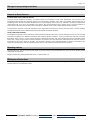
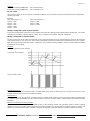
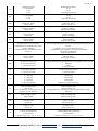
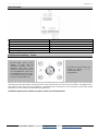
Connection Plan
1 EC fan GND 7 L
2 EC fan (0..10 V) 8 N
3 9 input for NTC 10 K / floating contact
4 Cooling 10
5 Heating 11 Modbus A
6 230 V digital input 12 Modbus B
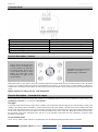
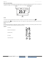
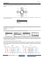
Function Description - Buttons
On the touch surface, there are adjustment options for setpoint and fan speed regulation.
With power-button (5), the device can be set in standby mode by pressing the button (if keycard-switch is NOT used). If the button
is used as a occupancy button, the button must be pressed for at least 3s, in all other cases, a short actuation is sufficient. In
standby mode, the display and all outputs are switched off (controller deactivated). The frost and heat protection monitoring remains
active.
Modbus registers can still be read (e.g. room temperature).
Function Description – Controller/Fan stages
Room temperature controls for heating and cooling can be individually adjusted and can be achieved as required using a “2-
point/3-point controller” or a continuous “PI controller”.
Fan stages
In automatic mode the fan speed is linked to the controller. The assignment of the fan stage to the control (heating / cooling, only
heating, only cooling) is freely selectable. To ensure that the fan motor starts reliably, a period of time can be configured in which
the fan starts with maximal value. Using one or more time channels, the fan control have to be set per timechannel and per period.
Via the touch surface the user has the option to override the settings of the device every time. When the next time channel starts,
the fan speed is set to the configured value. The fan is set to automatic mode when the user changes the occupancy state
(occupied↔unoccupied).
EC Fan automatic mode
The 0..10 V (0..100%) control of the fan is proportional to the calculated manipulated variable of the PI controller.
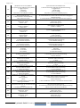
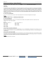
The buttons (3) and (4) change the
setpoint in the range ± 3 ° C
(default setting, configurable).
The fan speed can be set by the
Buttons UP (1) and DOWN (2). 3
seconds without any interaction,
the display returns back to main
screen. While pressing of these
buttons, the white LED of the
Power-button (5) lights up for
visual feedback.

Issue date: 09.03.2018 Page 5 / 27
Systemair GmbH Germany [email protected] oder http://www.systemair.de/
Example:
Calculated actuating variable 65% → Fan control with 6,5 V.
Calculated actuating variable 22% → Fan control with 2,2 V.
EC Fan manual
Up to 5 steps (steps) can be set using the configuration software. The set number of steps is divided linearly to the manipulated
variable of 0..100%.
Example:
Max. steps (stages) = 5
Stage 1 = 20%
Stage 2 = 40%
Stage 3 = 60%
Stage 4 = 80%
Stage 5 = 100%
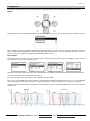
Heating/ cooling with 2-point-/ 3-point-controller
In the case of temperature control, the 2-point controller only knows the switching states heating ON and heating OFF. The 3-point
controller also knows the switching state of cooling. Two - and three-point controller work with a hysteresis.
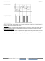
Heating/ cooling with PI-controller (PWM)
The time response of the PI control loop depends on the control parameters xp for the proportional area and tn for the reset time
of the integral range. In case of an error, the P portion immediately changes the position value proportionally to the error variable,
while the integral portion takes effect after a certain time. The resulting actuating variable is output as a pulse-width-modulated
signal directly to the outputs.
Example:
t in min., cycle time 30 mins. (default)
Proportional range Xp
The proportional band is the deviation in which controller emits 100% value. A small Xp leads to a stronger control action in case
of slight deviations, but increases the oscillation tendency.
Integral time Tn
The reset time Tn is the time which the I-component of the controller would require to produce the same positioning signal that the
P-component forms immediately once the control deviation is present. The effect of the I component decreases with increasing
reset time.
Minimum and maximum actuating variable
This setting defines a fixed minimum or maximum value of the actuating variable. The parameter "Mode selection actuating
variable" can be used to select whether the minimum actuating variable a) is retained until the controller changes its mode or b)
whether the actuating variable of the controller is output to the output only when the minimum actuating variable is exceeded.
Calculated control variable
Output control variable
Max. steps (stages) = 3
Stage 1 = 33%
Stage 2 = 66%
Stage 3 = 100%

Page 6 / 27 Issue date: 09.03.2018
Systemair GmbH Germany [email protected] oder http://www.systemair.de/
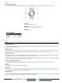
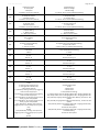
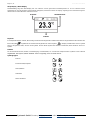
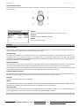
Main screen/ Value display
The Display shows the measured value of the internal sensor. The value of an external sensor will be shown if connected and
configured accordingly. The room thermostat controls in this case according to the external sensor.
Header Value display
Footer
Header
Current date and time will be displayed in the header. If enabled, ECO-mode status is indicated via symbol .
An attention symbol can be displayed in the header. This symbol has a higher priority than the ECO-mode symbol and is
prefixed instead of this.
Footer
Depending upon the heating or cooling mode, occupancy or window contact status, the corresponding symbols will be shown in
the footer. The symbol “active timechannel” will be shown only if active.
Symbols
Occupancy
Window contact/dew point
Heating/Cooling
Fan Speed
Active timechannel
….

Issue date: 09.03.2018 Page 7 / 27
Systemair GmbH Germany [email protected] oder http://www.systemair.de/
Configuration
The setpoint of the Modbus version can be adjusted to any particular requirements or overwritten by a higher-level control.
Buttons
The configuration menu is activated by simultaneously pressing the buttons “up” (A), “left” (D) and “right” (B) for at least 3 seconds.
Menu navigation on the touch-surface is performed by pressing the buttons “up” (A), “down” (C), “left” (D), “right” (B) or the power
button. Choose the desired parameter and press “right” (B) to open up the submenu. The menu will default after 30 seconds if no
button is pressed. To exit the menu select the header line and press “left” (D)
Time channels
Set point and timer can be set in this menu. Three different time channels with four periods of time are available. The Time channels
are prioritised. Channel 3 has the highest priority.
Choose the time channel and press “right” to enter the submenu. It is possible to select the total week as well as individual days
The selected parameter will be marked with the symbol
To edit the parameter of the selected timer, select “Periods” and press “right”.
ECO-mode is also available in the menu “Periods”, when selecting the dead zone increase from 2 °C to 10 °C. The adjustable
dead zone between the activation of heating or cooling modes enables an optimisation between comfort and energy saving.
The dead zone between heating and cooling in the ECO-mode will be set to the configured deadband range (see common settings,
default 10.0 K).

Page 8 / 27 Issue date: 09.03.2018
Systemair GmbH Germany [email protected] oder http://www.systemair.de/
Modbus parameter menu
The configuration menu is activated by simultaneously pressing the buttons “up” (A), “down” (C) for at least 5 seconds.
Inputs
Sensor (NTC10K)
The value of an external sensor will be shown if connected and configured accordingly. In this case, the room thermostat controls
according to the external sensor.
Change-Over DI
Which controller is active depends on the state of the Change-Over contact. (Factory default: contact open heating controller
active, contact closed cooling controller active). The terminals 3 and 4 are used as outputs for heating rsp. cooling.
Change-Over Sensor
The Change-Over Sensor is used for switching between heating and cooling mode automatically. If the temperature is below 19 °
C, the controller is in cooling mode. If it is above 28 ° C, it is a heating mode.
If an input is configured as a change-over, the room thermostat is automatically in 2-pipe operating mode and both outputs
(terminals 3 and 4) are used as outputs for heating rsp. cooling.
Window contact/Energy hold off
If a window contact is enabled via the digital input, the reference will switch to a setback set point (Heat SP/Cool SP).
Dewpoint
An active dewpoint contact locks the cooling controller.
Occupancy
If occupancy-function is active, the symbol will be displayed automatically. In state of “unoccupied” the heating set point is reduced
by 2K (default setting) rsp. the cooling set point raised by 2K.
Keycard-Switch
When the card is not inserted, the device is switched in sleep mode. Operation of the keys is locked, the display is switched off
and the controller adjusts to the nominal values of the "unoccupied"-State.
Address
Adjustable address (1-247)
Baud rate
9600Bd | 19200Bd | 38400Bd | 57600Bd
Parity
Non | odd | even

Issue date: 09.03.2018 Page 9 / 27
Systemair GmbH Germany [email protected] oder http://www.systemair.de/
Diagnostics Menu
To access the diagnostics menu, select the header in the startscreen of the parameter menu, and press the ENTER key. Here you
will find various information, such as device type, software version, state of the inputs and outputs and controller state (current
manipulated variable).
Application notice
SD-Card
Micro SD cards can be used to upload a new firmware or a new device configuration. With the PC configuration tool a configuration
file with extended parameter set can be created and uploaded via SD card. Only SD cards formatted in the FAT file system can
be used! NTFS and exFAT file systems are not supported.
Boot Loader
Because of an integrated bootloader a new application (update, upgrade) can be uploaded by means of a SD card. To
insert the SD card, the upper part must be removed. If the boot loader is activated, the ring illumination blinks in a 1s
cycle, while display is not triggered! After recognition of a SD card with a valid application the update process is started.
Now, ring illumination blinks in a 300ms cycle. After a successful update process (Duration approx. 2-3 minutes!) the
new application is started automatically. Afterwards, SD card shall be removed!
Software:
A detailed description of the parameter and the configuration software can be found using the following link.
The parameters for the display, set point and the controller can only be changed via the configuration
software.
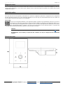
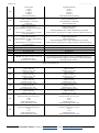
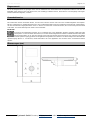
Dimensions (mm)

Page 10 / 27 Issue date: 09.03.2018
Systemair GmbH Germany [email protected] oder http://www.systemair.de/
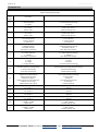
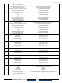
Parameter list
Modbus Holding Register (R/W)
Register
Data
Address
Description
3
(#) Language
0: German (default)
1: English
(#) Sprache
0: deutsch (Werkseinstellung)
1: englisch
4
(#) Offset internal sensor
0,0 - 15,0°C
Default: 0,0°C
(#) Offset interner Sensor
0-150 ≙ 0,0 - 15,0°C
Werkseinstellung: 0,0°C
5
(#) Offset external sensor
0,0 - 15,0°C
Default: 0,0°C
(#) Offset externer Sensor
0-150 ≙ 0,0 - 15,0°C
Werkseinstellung: 0,0°C
6
(#) Unit temperature
0: not implemented
1: °Celsius (default)
2: °Fahrenheit
(#) Einheit Temperatur
0: nicht benutzt
1: °Celsius (default)
2: °Fahrenheit
7
(#) Format time
0: 24h(pm) (default)
64 (=0x40): 12h(am)
255 (=0xFF): not displayed
(#) Format Uhrzeit
0: 24h(pm) (Werkseinstellung)
64 (=0x40): 12h(am)
255 (=0xFF): keine Anzeige
8
(#) Format date
0: TT.MM.JJ (default)
1: JJ/MM/TT
255 (=0xFF): not displayed
(#) Format Datum
0: TT.MM.JJ (Werkseinstellung)
1: JJ/MM/TT
255 (=0xFF): keine Anzeige
9
(#)Number of fan coil stages
1: 1 stage
2: 2 stages
3: 3 stages (default)
(#)Anzahl Lüfterstufen
1: 1 Stufe
2: 2 Stufen
3: 3 Stufen (Werkseinstellung)
10
(#) Display main screen
0: Room temperature display (default)
1: Set point base display
2: Set point offset display
(#) Anzeige Hauptbildschirm
0: Raumtemperaturanzeige (Werkseinstellung)
1: Basis-Sollwert Anzeige
2: Sollwert-Offset Anzeige
11
(#) Footer symbol 1
0x00hex: No symbol (default)
0x01hex: Heating/cooling
0x02hex: Occupancy
0x03hex: Window contact/dew point
0x04hex: Fan coil stage
0x05hex:Active time channel
(#) Fußzeile Symbol 1
0: kein Symbol (Werkseinstellung)
1: Heizen/Kühlen
2: Präsenz
3: Fensterkontakt/Taupunkt
4: Lüfterstufe
5: Aktiver Zeitkanal
12
(#) Footer symbol 2
See symbol 1
(#) Fußzeile Symbol 2
s. Symbol 1
13
(#) Footer symbol 3
See symbol 1
(#) Fußzeile Symbol 3
s. Symbol 1
14
(#) Footer symbol 4
See symbol 1
(#) Fußzeile Symbol 4
s. Symbol 1
15
(#) Footer symbol 5
See symbol 1
(#) Fußzeile Symbol 5
s. Symbol 1
16
(#) Brightness background illumination LCD
0-100dez = 0-100%
Default: 90%
(#) Helligkeit Hintergrundbeleuchtung LCD
0-100 = 0-100%
Werkseinstellung: 90%
17
(#) Brightness ring
0-100dez = 0-100%
Default: 20%
(#) Helligkeit Ring
0-100 = 0-100%
Werkseinstellung: 20%

Issue date: 09.03.2018 Page 11 / 27
Systemair GmbH Germany [email protected] oder http://www.systemair.de/
18
(#) Input 1: Universal input
0: Not used (default)
1: External temperature sensor (NTC10k)
2: Change-over sensor (NTC10k)
3: Change-over make contact (NO = normally
open)
4: Window contact make contact
5: Occupancy make contact
6: Dew point make contact
7: Change-over break contact (NC = normally
closed)
8: Window contact break contact
9: Occupancy break contact
10: Dew point break contact
11: Keycard switch make contact
12: Keycard switch break contact
(#) Eingang 1 Universaleingang
0: Nicht verwendet (Werkseinstellung)
1: Externer Temperatursensor (NTC10k)
2: Change-Over Sensor (NTC10k)
3: Change-Over Schließer
4: Fensterkontakt Schließer
5: Präsenzkontakt Schließer
6: Taupunktkontakt Schließer
7: Change-Over Öffner
8: Fensterkontakt Öffner
9: Präsenzkontakt Öffner
10: Taupunktkontakt Öffner
11: Keycard Switch Schließer
12: Keycard Switch Öffner
19
(#) Input 3: 230V Device type Fancoil_EC
0: Not used (default)
3: Change-over make contact (NO = normally
open)
4: Window contact make contact
5: Occupancy make contact
6: Dew point make contact
7: Change-over break contact (NC = normally
closed)
8: Window contact break contact
9: Occupancy break contact
10: Dew point break contact
(#) Eingang 3 230V bzw. potentialfrei bei EC-Variante
0: Nicht verwendet (Werkseinstellung)
3: Change-Over Schließer
4: Fensterkontakt Schließer
5: Präsenzkontakt Schließer
6: Taupunktkontakt Schließer
7: Change-Over Öffner
8: Fensterkontakt Öffner
9: Präsenzkontakt Öffner
10: Taupunktkontakt Öffner
20
(#) Set point after reset
0,0 - 50,0°C
Default 21,0°C
(#) Sollwert nach Reset
0-500 ≙ 0,0 - 50,0°C
Werkseinstellung: 21,0°C
21
(#) Adjustable range set point
0-100 ≙ 0,0 - 10,0°C
Default: 3,0°C
(#) Sollwertverstellbereich
0-100 ≙ 0,0 - 10,0°C
Werkseinstellung: 3,0°C
22
(#) Set point step range
0-100 ≙ 0,0 - 10,0°C
Default: 0,5°C
(#) Sollwertschrittweite
0-100 ≙ 0,0 - 10,0°C
Werkseinstellung: 0,5°C
23
(#) Dead band comfort mode
0-150 ≙ 0,0 - 15,0°C
Default: 2,0°C
(#) Totzone Komfortbetrieb
0-150 ≙ 0,0 - 15,0°C
Werkseinstellung: 2,0°C
24
(#) Dead band ECO mode
0-150 ≙ 0,0 - 15,0°C
Default: 10,0°C
(#) Totzone ECO-Modus
0-150 ≙ 0,0 - 15,0°C
Werkseinstellung: 10,0°C
25
(#) Set point adjustment standby
0-150 ≙ 0,0 - 15,0°C
Default: 2,0°C
(#) Sollwertverschiebung Präsenz
0-150 ≙ 0,0 - 15,0°C
Werkseinstellung: 2,0°C
26
(#) Frost Protection
0-150 ≙ 0,0 - 15,0°C
Default: 7,0°C
(#) Frostschutz
0-150 ≙ 0,0 - 15,0°C
Werkseinstellung: 7,0°C
27
(#) Heat protection
0-500 ≙ 0,0 - 50,0°C
Default: 35,0°C
(#) Hitzeschutz
0-500 ≙ 0,0 - 50,0°C
Werkseinstellung: 35,0°C
28
(#) Controller hysteresis
0-150 ≙ 0,0 - 15,0°C
Default: 1,0°C
(#) Reglerhysterese
0-150 ≙ 0,0 - 15,0°C
Werkseinstellung: 1,0°C
29
(#) Controller Mode after device reset
0: Off
1: Heating
2: Cooling
3: Auto (default)
17 (=0x11hex): Heating mode (auto) triggering
heat and cool relay/output
18 (=0x12hex): Cooling mode (auto) triggering
heat and cool relay/output
(#) Regler Modus nach Geräteneustart
0: Aus
1: Heizen
2: Kühlen
3: Auto (Werkseinstellung)
17 (=0x11): Heizen Auto mit Ausgang Heizen AN + Ausgang Kuehlen AN
18 (=0x12): Kühlen Auto mit Ausgang Heizen AN + Ausgang Kuehlen AN

Page 12 / 27 Issue date: 09.03.2018
Systemair GmbH Germany [email protected] oder http://www.systemair.de/
30
(#) Treshold stage 1 ON
0-150 ≙ 0,0 - 15,0°C
Default : 0,0°C
(#) Schwellwert Lüfterstufe 1 Ein
0-150 ≙ 0,0 - 15,0°C
Werkseinstellung : 0,0°C
30
(#)Maximum fan coil value (100%) at
temperature deviation
0-150 ≙ 0,0 - 15,0°C
Default : 4,0°C
(#) Abweichung Temperatur für maximale Lüfteransteuerung (100%)
0-150 ≙ 0,0 - 15,0°C
Werkseinstellung : 4,0°C
31
(#) Treshold stage 2 ON
0-150 ≙ 0,0 - 15,0°C
Default :1,5°C
(#) Schwellwert Lüfterstufe 2 Ein
0-150 ≙ 0,0 - 15,0°C
Werkseinstellung :1,5°C
32
(#) Treshold stage 3 ON
0-150 ≙ 0,0 - 15,0°C
Default : 3,0°C
(#) Schwellwert Lüfterstufe 3 Ein
0-150 ≙ 0,0 - 15,0°C
Werkseinstellung : 3,0°C
33
(#)Valve protection release
0: Lock
1: Release (default)
(#)Ventilschutz Freigabe
0: Sperre
1: Freigabe (Werkseinstellung)
34
#) Time channel 1 weekdays
Bit0: Monday
Bit1: Tuesday
Bit2: Wednesday
Bit3: Thursday
Bit4: Friday
Bit5: Saturday
Bit6: Sunday
Default: 0
Example:
7 ≙ 0x0Fhex = Monday, Tuesday, Wednesday,
Thursday
(#) Zeitkanal 1 Wochentage
Bit0: Montag
Bit1: Dienstag
Bit2: Mittwoch
Bit3: Donnerstag
Bit4: Freitag
Bit5: Samstag
Bit6: Sonntag
Werkseinstellung: 0
Beispiel:
7 ≙ 0x0Fhex = Montag, Dienstag, Mittwoch, Donnerstag
35
(#)Time channel 1 period 1: Start time hour
0 – 23h
Default: 0
(#) Zeitkanal 1 Startzeit Stunde Abschnitt 1
0 – 23h
Werkseinstellung: 0
36
(#)Time channel 1 period 1: Start time minute
0 – 59m
Default: 0
(#) Zeitkanal 1 Startzeit Minute Abschnitt 1
0 – 59min
Werkseinstellung: 0
37
(#)Time channel 1 period 1: Set point
0-500 ≙ 0,0 – 50,0°C
Default: 21,0°C
(#) Zeitkanal 1 Sollwert Abschnitt 1
0-500 ≙ 0,0 – 50,0°C
Werkseinstellung: 21,0°C
38
3 stages fan coil type (3 relays)
(#)Time channel 1 period 1: Fan coil stage
0: Off
1: Stage 1
2: Stage 2
3: Stage 3
4: Automatic (default)
Variante mit 3 Lüfterstufen (3 Relais)
(#) Zeitkanal 1 Lüfterstufe Abschnitt 1
0: Aus
1: Stufe 1
2: Stufe 2
3: Stufe 3
4: Automatik (Werkseinstellung)
38
EC-fan coil type (0-10V)
(#)Time channel 1 period 1: Fan coil stage
0x00hex: Off
0x01hex: Automatic (default)
Variante mit EC-Lüfter (0-10V)
(#) Zeitkanal 1 Lüfteransteuerung Abschnitt 1
0x00hex: Aus
0x01hex: Automatik (Werkseinstellung)
39
(#)Time channel 1 period 1: ECO mode
0: ECO Mode off (default)
1: ECO Mode active
(#) Zeitkanal 1 ECO-Modus Abschnitt 1
0x00hex: ECO-Modus aus (Werkseinstellung)
0x01hex: ECO-Modus aktiv
97
(#) Daylight saving
0: disabled (default)
1: CET
255 (=0xFF): not displayed
(#) Sommer-/Winterzeitumstellung
0: keine Umstellung (Werkseinstellung)
1: Mitteleuropäische Zeit
98
(#)Fan coil assignment
0: Heating/Cooling (default)
1: Heating
2: Cooling
(#)Zuordnung Lüfterstufen
0: Heizen/Kühlen (Werkseinstellung)
1: Heizen
2: Kühlen
98
(#)Fan coil assignment
0: heating/cooling (default)
1: heating
2: cooling
(#)Zuordnung Lüfterstufen
0: Heizen/Kühlen (Werkseinstellung)
1: Heizen
2: Kühlen

Issue date: 09.03.2018 Page 13 / 27
Systemair GmbH Germany [email protected] oder http://www.systemair.de/
99
(#) Max heating load
0: <2A (default)
1: <4A
2: <6A
(#) Maximale Last Heizen
0: <2A
1: <4A
2: <6A (Werkseinstellung)
100
(#) Max cooling load
0: <2A (default)
1: <4A
2: <6A
(#) Maximale Last Kühlen
0: <2A
1: <4A
2: <6A (Werkseinstellung)
102
(#) Proportional band Xp heating
0-100 ≙ 0,0 - 10,0°C
Default: 2,0°C
(#) Proportionalbereich Xp Regler Heizen
0-100 ≙ 0,0 - 10,0°C
Werkseinstellung: 2,0°C
103
(#) Reset time Tn heating
0-1000 ≙ 0-1000min
Default: 30m
(#) Nachstellzeit Tn Regler Heizen
0-1000 ≙ 0-1000min
Werkseinstellung: 30min
104
(#) Minimum actuating variable heating
0-100 ≙ 0–100%
Default: 0%
(#) Minimale Stellgröße Regler Heizen
0-100 ≙ 0–100%
Werkseinstellung:0%
105
(#) Maximum actuating variable heating
0-100 ≙ 0–100%
Default: 100%
(#) Maximale Stellgröße Regler Heizen
0-100 ≙ 0–100%
Werkseinstellung: 100%
106
(#) Mode Selection Control Variable
0: Use Minimal Control Variable with control
variable = 0 (default)
1: Use Minimal Control Variable with control
variable > 0
(#) Verhalten bei minimaler Stellgröße
0 - minimale Stellgröße bleibt bis Moduswechsel (Werkseinstellung)Stellgröße
wird erst
ausgegeben, wenn minimale Stellgröße erreicht
1 – Stellgröße wird erst ausgegeben, wenn minimale Stellgröße
erreichtminimale Stellgröße
bleibt bis Moduswechsel
107
(#) PWM cycle time
5-60 ≙ 5 – 60min
Default: 30min
(#) PWM-Zykluszeit
5-60 ≙ 5 – 60min
Werkseinstellung: 30min
108
(#) Heating controller type
0: PI-controller (default)
1: Two-point controller
(#) Funktion Regler Heizen
0 - PI-Regler (Werkseinstellung)Stellgröße wird erst ausgegeben, wenn minimale
Stellgröße
erreicht
1 - Zweipunkt-Regler
109
(#) Cooling controller type
0: PI-controller (default)
1: Two-point controller
(#) Funktion Regler Kühlen
0 - PI-Regler (Werkseinstellung)
1 - Zweipunkt-Regler
110
(#)Steps fan coil control
1: = 100% step
2: = 50% steps
3: = 33% steps
4: = 25% steps
5: = 20% steps (default)
(#)Schritte Lüfterstufenansteuerung
1: 100% Schritt
2: 50% Schritte
3: 33% Schritte
4: 25% Schritte
5: 20% Schritte (Werkseinstellung)
111
(#)Fan coil minimum
0-100 ≙ 0-100% (0-10V)
Default : 0%
Special case 0x8xxxhex, see description: Fan coil
minimum, Fan coil maximum
(#)Lüfter Minimum
0-100 ≙ 0-100% (0-10V)
Werkseinstellung : 0%
Sonderfall: 0x8xxxhex, siehe auch Beschreibung Lüfter Minimum, Lüfter
Maximum
112
(#)Fan coil maximum
0-100 ≙ 0-100% (0-10V)
Default: 100%
(#)Lüfter Maximum
0-100 ≙ 0-100% (0-10V)
Werkseinstellung: 100%
113
(#) Start-up time fan coil
0-30s ≙ 0 – 300
Default: 1s
(#) Anlaufzeit Lüfter
0-30s ≙ 0 – 300
Werkseinstellung : 1s
113
(#) Startup time fan coil
0–300 ≙ 0 – 30s
Default: 1s
(#) Anlaufzeit Lüfter
0–300 ≙ 0 – 30s
Werkseinstellung: 1s
114
(#) Display set point adjustment
0: Set point offset (default)
1: Set point base
2: Set point stages (-3,-2, -1, 0, +1, +2, +3)
(#) Anzeige Sollwertverstellung
0: Sollwert Offset (Werkseinstellung)
1: Basis-Sollwert
2: Sollwert in Stufen (z.B. -3,-2, -1, 0, +1, +2,+3)

Page 14 / 27 Issue date: 09.03.2018
Systemair GmbH Germany [email protected] oder http://www.systemair.de/
115
(#) Special function of key ON/OFF
0: no special function (ON/OFF active) (default)
1: Toggle occupancy
2: Occupied
3: Unoccupied
255 (=0xFF): Locked (ON/OFF disabled)
(#) Sonderfunktion der AN/AUS-Taste
0: keine Sonderfunktion (AN/AUS aktiv) (Werkseinstellung)
1: Toggle Präsenz
2: Raum belegt
3: Raum unbelegt
255 (=0xFF): Taste gesperrt (AN/AUS gesperrt)
124
(#) Lock parameter menu
0: Key combination released (default)
1: Key combination locked
(#) Sperre des Parametermenüs
0: Tastenkombination zum Aufruf des Parametermenüs freigegeben
(Werkseinstellung)
1: Tastenkombination zum Aufruf des Parametermenüs gesperrt
125
(#) Proportional band Xp cooling
0-100 ≙ 0,0 - 10,0°C
Default: 2,0°C
(#) Proportionalbereich Xp Regler Kühlen
0-100 ≙ 0,0 - 10,0°C
Werkseinstellung: 2,0°C
126
(#) Reset time Tn cooling
0-1000 ≙ 0-1000min
Default: 30m
(#) Nachstellzeit Tn Regler Kühlen
0-1000 ≙ 0-1000min
127
(#) Minimum actuating variable cooling
0-100 ≙ 0–100%
Default: 0%
(#) Minimale Stellgröße Regler Kühlen
0-100 ≙ 0–100%
128
(#) Maximum actuating variable cooling
0-100 ≙ 0–100%
Default: 100%
(#) Maximale Stellgröße Regler Kühlen
0-100 ≙ 0–100%
Werkseinstellung: 100%
129
(#) Switch/control behavior fan stages
-1: independent (default)
0-20 ≙ 0%-20%: dependent
(#)Schalt-/Steuerverhalten Lüfterstufen
-1: Unabhängig (Werkseinstellung)
0-20 ≙ 0%-20%: Abhängig
129
(#) Switch/control behavior fan stages
-1: independent (default)
0-20 ≙ 0%-20%: dependent
(#)Schalt-/Steuerverhalten Lüfterstufen
-1: Unabhängig (Werkseinstellung)
0-20 ≙ 0%-20%: Abhängig
130
(#) Device state after power ON
0: Standby
1: Laste state
2: On (default)
(#) Gerätezustand nach Power-ON
0: Standby
1: Letzter Zustand
2: An (Werkseinstellung)
131
(#) Device values after Power ON
0: Keep last values (default)
1: Reset values
(#) Werte nach Power-ON
0: Letzte Werte behalten (Werkseinstellung)
1: Werte rücksetzen
132
(#)Effective direction of heating output
0: Make contact (default)
1: Break contact
(#) Wirksinn Relais Heizen
0: Schließer (Werkseinstellung)
1: Öffner
133
(#)Effective direction of cooling output
0: Make contact (default)
1: Break contact
(#) Wirksinn Relais Kühlen
0: Schließer (Werkseinstellung)
1: Öffner
134
(#) Keys Fan stage with / without AUTO
0: with AUTOMATIC (default)
1: without AUTOMATIC
(#) Tasten Lüfterstufe mit/ohne AUTO
0: mit AUTOMATIK (Werkseinstellung)
1: ohne AUTOMATIK
134
(#) Keys Fan stage with / without AUTO
0: with AUTOMATIC (default)
1: without AUTOMATIC
(#) Tasten Lüfterstufe mit/ohne AUTO
0: mit AUTOMATIK (Werkseinstellung)
1: ohne AUTOMATIK
135
(#)Behavior of set point offset at occupancy
change
0: Retain (default)
1: Reset
2: Reset during UNOCCPIED and restore after
switching to OCCUPIED
(#) Verhalten Sollwert-Offset bei Präsenzwechsel
0: Wert behalten (Werkseinstellung)
1: Wert zurücksetzen
2: Wert in UNBELEGT rücksetzen und bei BELEGT wiederherstellen
136
(#) Occupied / ECO override
0: Occupancy State does not override ECO mode
(default)
1: OCUPIED state overrides ECO mode
(#) Präsenz-/ECO-Übersteuerung
0: Präsenzzustand ohne Einfluss auf ECO-Modus (Werkseinstellung)
1: BELEGT-Zustand übersteuert ECO-Modus
255
Basic set point
0-500 ≙ 0,0 - 50,0°C
Default: 21,0°C
Basissollwert
0-500 ≙ 0,0 - 50,0°C
Werkseinstellung: 21,0°C
256
Set point offset
0-150 ≙ 0,0 - 15,0°C
Default: 0°C
Sollwertoffset
0-150 ≙ 0,0 - 15,0°C
Werkseinstellung: 0°

Issue date: 09.03.2018 Page 15 / 27
Systemair GmbH Germany [email protected] oder http://www.systemair.de/
257
Default Occupancy
0: Unoccupied
1: Occupied
-1 ≙ 0xFFFF: No function (default)
Vorgabe Präsenz
0: Raum unbelegt
1: Raum belegt
-1 ≙ 0xFFFF: keine Funktion (Werkseinstellung)
258
Default dewpoint
0: Dewpoint inactive
1: Dewpoint active
-1 ≙ 0xFFFF: No function (default)
Vorgabe Taupunkt
0: Taupunkt inaktiv
1: Taupunkt aktiv
-1 ≙ 0xFFFF: keine Funktion (Werkseinstellung)
259
Default window contact/ energy hold off
0: Window closed
1: Window opened
-1 ≙ 0xFFFF: No function (default)
Vorgabe Fensterkontakt/Energiesperre
0: Fenster geschlossen
1: Fenster offen
-1 ≙ 0xFFFF: keine Funktion (Werkseinstellung)
260
Default change-over
0: Mode heating
1: Mode cooling
-1 ≙ 0xFFFF: No function
Vorgabe Change-Over
0: Modus Heizen
1: Modus Kühlen
-1 ≙ 0xFFFF: keine Funktion
261
Device On/Off
0: On (default)
1: Off
Gerät Ein/Standby
0: Ein (Werkseinstellung)
1: Standby
262
Release of keys
0: All keys released (default)
1: Lock all keys
2: Lock fan coil keys
Freigabe Tasten
0: Freigabe aller Tasten (Werkseinstellung)
1: Sperre aller Tasten
2: Sperre Tasten zur Lüfterstufenverstellung
263
Default alarm
0: No alarm
1: Alarm
Vorgabe Alarm
0: kein Alarm (Werkseinstellung)
1: Alarm
264
Time hour
0 – 23
Default: 12
Uhrzeit Stunde
0 – 23
Werkseinstellung: 12
265
Time minute
0 – 59
Default: 0
Uhrzeit Minute
0 – 59
Werkseinstellung: 0
266
Date day
1 – 31
Default: 1
Datum Tag
1 – 31
Werkseinstellung: 1
267
Date month
1 – 12
Default: 1
Datum Monat
1 – 12
Werkseinstellung: 1
268
Date year
15 – 99
Default: 15
Datum Jahr
15 – 99
Werkseinstellung: 15
269
Default controller mode
0: Off
1: Heating mode enabled (auto)
2: Cooling mode enabled (auto)
3: Auto mode (default)
17 (=0x11hex): Heating mode (auto) triggering
heat and cool relay/output
18 (=0x12hex): Cooling mode (auto) triggering
heat and cool relay/output
-255 (=0xFF01hex): Set heating output (manual
mode), Type EC: Only Symbol
-254 (=0xFF02hex): Set cooling output (manual
mode), Type EC: Only Symbol
-239 (=0xFF11hex): Heating mode (manual)
triggering heat and cool relay/output, Type EC:
Only
Symbol
-238 (=0xFF12hex): Cooling mode (manual)
triggering heat and cool relay/output, Type EC:
Only
Symbol
Vorgabe Reglermodus
0: Aus
1: Heizen Auto
2: Kühlen Auto
3: Auto (Werkseinstellung)
17 (=0x11): Heizen Auto mit Ausgang Heizen AN + Ausgang Kuehlen AN
18 (=0x12): Kühlen Auto mit Ausgang Heizen AN + Ausgang Kuehlen AN
-255 (=0xFF01): Ausgang Heizen AN (manueller Modus), Variante EC: Nur
Symbol
-254 (=0xFF02): Ausgang Kühlen AN (manueller Modus) , Variante EC: Nur
Symbol
-239 (=0xFF11): Heizen mit Ausgang Heizen AN + Ausgang Kuehlen AN(
manueller Modus),
Variante EC: Nur Symbol
-238 (=0xFF12): Kühlen mit Ausgang Heizen AN + Ausgang Kuehlen AN(
manueller Modus),
Variante EC: Nur Symbol

Page 16 / 27 Issue date: 09.03.2018
Systemair GmbH Germany [email protected] oder http://www.systemair.de/
270
Fan coil stage
0: Off
1: Stage 1
2: Stage 2
3: Stage 3
3: Automatic (default)
Vorgabe Lüfterstufe
0: Aus
1: Stufe 1
2: Stufe 2
3: Stufe 3
4: Automatik (Werkseinstellung)
270
Default fan coil
0-100 ≙ 0-100% Manual
-256 (=0xFF00hex) = Automatic
Default: 0%
Vorgabe Lüfter
0-100 ≙ 0-100% Manuell
-256 (=0xFF00hex) = Automatik
Werkseinstellung: 0%
271
Default output heating
Device type Fancoil_EC:
0-100 (=0x00-0x64) = 0-10V in manual mode, no
symbol
65535 (=0xFFFF): output will be controlled
internally (default)
Vorgabe Ausgang Heizen
Variante Fancoil_EC:
0-100 (=0x00-0x64) entspr. 0-10V im Handmodus, kein Symbol
65535 (=0xFFFF): Ausgang wird von Regler angesteuert (Werkseinstellung)
272
Default output cooling
Device type Fancoil_EC:
0-100 (=0x00-0x64) = 0-10V in manual mode, no
symbol
65535 (=0xFFFF): output will be controlled
internally (default)
Vorgabe Ausgang Kühlen
Variante Fancoil_EC:
0-100 (=0x00-0x64) entspr. 0-10V im Handmodus, kein Symbol
65535 (=0xFFFF): Ausgang wird von Regler angesteuert (Werkseinstellung)
40-44
(#) Time channel 1 period 2
(#) Zeitkanal 1 Abschnitt2
45-49
(#) Time channel 1 period 3
(#) Zeitkanal 1 Abschnitt3
50-54
(#) Time channel 1 period 4
(#) Zeitkanal 1 Abschnitt4
55-75
(#) Time channel 2
(#) Zeitkanal 2
76-96
(#) Time channel 3
(#) Zeitkanal 3
The registers marked with # are saved in
EEPROM. They shall be written only during
configuration of the
device and not at runtime!
Die mit # gekennzeichneten Register werden im EEPROM gespeichert. Sie
dürfen nur während der Konfiguration des Gerätes und nicht im laufenden
Betrieb geschrieben werden!
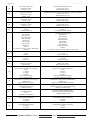
Modbus Input Register (R)
511
Set point heating
0-500 ≙ 0-50,0°C
Example: 21,5°C = 215
Sollwert Heizen
0-500 ≙ 0-50,0°C
Beispiel: 21,5°C = 215
512
Set point cooling
0-500 ≙ 0-50,0°C
Example: 21,5°C = 215
Sollwert Kühlen
0-500 ≙ 0-50,0°C
Beispiel: 21,5°C = 215
513
Set point offset
0-500 ≙ 0-50,0°C
Example: 21,5°C = 215
Sollwert Offset
0-150 ≙ 0-15,0°C
Beispiel: 3,0°C = 30
514
Internal temperature sensor
0-500 ≙ 0-50,0°C
Example: 21,5°C = 215
Interner Temperatursensor
0-500 ≙ 0-50,0°C
Beispiel: 21,5°C = 215
515
External temperature sensor
0-500 ≙ 0-50,0°C
Example: 21,5°C = 215
Externer Temperatursensor
0-500 ≙ 0-50,0°C
Beispiel: 21,5°C = 215
516
Output heating
Device type Fancoil and Fancoil_EC:
0: Off
1: On
Device type Fancoil_EC:
0-100 (=0x00-0x64) = 0-10V
Ausgang Heizen
Varianten Fancoil und Fancoil_EC:
0: Aus
1: Ein
Variante Fancoil_EC:
0-100 (=0x00-0x64) entspr. 0-10V
517
Output cooling
Device type Fancoil and Fancoil_EC:
0: Off
1: On
Device type Fancoil_EC:
0-100 (=0x00-0x64) = 0-10V
Ausgang Kühlen
Varianten Fancoil und Fancoil_EC:
0: Aus
1: Ein
Variante Fancoil_EC:
0-100 (=0x00-0x64) entspr. 0-10V

Issue date: 09.03.2018 Page 17 / 27
Systemair GmbH Germany [email protected] oder http://www.systemair.de/
518
State fan coil stage
0x00hex: Off
0x01hex: Stage 1
0x02hex: Stage 2
0x03hex: Stage 3
-255 (=0xFF01hex): Auto stage 1
-254 (=0xFF02hex): Auto stage 2
-253 (=0xFF03hex): Auto stage 3
Zustand Lüfterstufe
0: Aus
1: Stufe 1
2: Stufe 2
3: Stufe 3
-255 (=0xFF01hex): Auto Stufe 1
-254 (=0xFF02hex): Auto Stufe 2
-253 (=0xFF03hex): Auto Stufe 3
519
State input 1: Universal
0: Open
1: Closed
Zustand Eingang 1 Universal
0: Offen
1: Geschlossen
520
State input 3: 230V
0: Open
1: Closed
Zustand Eingang 3 230V
0: Offen
1: Geschlossen
521
Occupancy state
0: Room unoccupied
1: Room occupied
-1 ≙ 0xFFFF: No function
Zustand Präsenz
0: Raum unbelegt
1: Raum belegt
-1 ≙ 0xFFFF: keine Funktion
522
State dewpoint
0: Dewpoint inactive
1: Dewpoint active
-1 ≙ 0xFFFF: No function
Zustand Taupunkt
0: Taupunkt inaktiv
1: Taupunkt aktiv
-1 ≙ 0xFFFF: keine Funktion
523
State window contact/energy hold off
0: Window closed
1: Window opened
-1 ≙ 0xFFFF: no function
Zustand Fensterkontakt/Energiesperre
0: Fenster geschlossen
1: Fenster offen
-1 ≙ 0xFFFF: keine Funktion
524
Actuating variable controller
0-100 (=0x00-0x64) ≙ 0-10V
Stellgröße Regler
0-100 (=0x00-0x64) entspr. 0-10V
525
Controller mode feedback
0: Off
1: Heating
2: Cooling
Modus Regler
0: Aus
1: Heizen
2: Kühlen

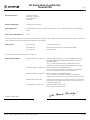
EU Declaration of conformity
TControl POD
1 (1)
GB
The manufacturer: Systemair GmbH
Seehöfer Straße 45
97944 Boxberg
Germany
Product designation: Temperature controller
Type designation: TControl POD 3s white, TControl POD 3s black, TControl POD EC white, TControl POD EC
black
Since year of manufacture:
2017
The manufacturer declares that the above mentioned products in their design and construction and the version marketed
by us complies with the harmonization legislation listed below:
EU directives: 2014/35/EU Low voltage directive
2014/30/EU
Directive electromagnetic compatibility (EMC)
2011/65/EU
RoHS directive
The following standards have been considered:
Harmonized standards:
DIN EN 50491-5-2:2010-11
General requirements for Home and Building Electronic
Systems (HBES) and Building Automation and Control
Systems (BACS) -
Part 5-2: EMC requirements for HBES/BACS used in
residential, commercial and light industry environment
DIN EN 61000-6-1:2007-10
Electromagnetic compatibility (EMC) -
Part 6-1: Generic standards - Immunity for residential,
commercial and light-industrial environments
DIN EN 61000-6-3:2011-09
Electromagnetic compatibility (EMC) -
Part 6-3: Generic standards - Emission standard for
residential, commercial and light-industrial environments
DIN EN 50581:2013-02
Technical documentation for the assessment of electrical
and electronic products with respect to the restriction of
hazardous substances
DIN EN 60730-1:2017-05
Automatic electrical controls -
Part 1: General requirements
Boxberg, 09.04.2018
ppa. Harald Rudelgass, technical director
Systemair GmbH, Seehöfer Straße 45, 97944 Boxberg, Germany
Phone: +49 (0) 7930 9272 0 Fax: +49 (0) 7930 9272 92 -en_GB-

Page 18 / 27 Issue date: 09.03.2018
Systemair GmbH Germany [email protected] oder http://www.systemair.de/
Bedienungsanleitung
Technische Änderungen vorbehalten
Stand: 09.03.2018
Version 56.6.1
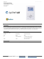
Anwendung
Das Fan-Coil Thermostat im hochwertigen Design dient zur Ansteuerung von Gebläsekonvektoren mit EC Lüftern. Es ist sowohl
für 2- und 4-Leiter-Register geeignet. Es besitzt 2 Relais und 1 Analogausgang 0-10V (Heizventil, Kühlventil und EC-Lüfter). Mit
seinem modernen Design kombiniert das Gerät ein 2,5“ LCD Display mit einer Touch-Oberfläche. Über die Parameter lassen sich
3 Zeitkanäle mit jeweils 4 Zeitabschnitten einstellen. Das Gerät ist konzipiert für die Montage in einer Unterputzdose.
Bezeichnung
TControl POD 3s white
TControl Beschreibung: Temperaturregelung
POD Name: POD
3s Lüfterregelungsart: 3s 3stufige Lüftersteuerung
EC 0-10V Lüftersteuerung
white Farbe: weiß oder schwarz
Parameterliste
Die Modbus Parameterliste finden Sie am Ende der englischen Anleitung.

Issue date: 09.03.2018 Page 19 / 27
Systemair GmbH Germany [email protected] oder http://www.systemair.de/
Technische Daten
Messgrößen
Temperatur
Netzwerktechnologie
RS485 Modbus, Baudrate 9.600, 19.200, 38.400 oder 57.600, Parität keine (2 Stoppbits), gerade oder
ungerade (1 Stoppbit)
Ausgang Spannung
0..10 V, Ansteuerung EC Lüfter
Ausgang Schaltkontakt
2x Schließkontakte (Heizen & Kühlen) 240 V, Last max. 3 A
Spannungsversorgung
85..260 V ~
Leistungsaufnahme
max. 2 VA (260 V ~)
Messbereich Temperatur
0..+50 °C
Genauigkeit Temperatur
±1 K (typ. bei 21 °C)
Eingänge
Eingang für NTC10k oder potentialfreien Kontakt
Eingang digital für potentialfreien Kontakt (230 V ~)
Bedienfunktionen
Sollwertverstellung 0..+50 °C
Anzeige
LCD 60x44 mm, 240x160 px., Hintergrundbeleuchtung weiß
Funktionen
integrierter PI- und Zweipunkt-/Dreipunktregler
Gehäuse
PC, gehärtetes Acrylglas mit hoher Kratzfestigkeit
Schutzart
IP30 gemäß DIN EN 60529
Anschluss elektrisch
Klemme 1..8
Schraubklemme max. 1,5 mm²
Klemme 9..12
Schraubklemme max. 1,0 mm²
Umgebungsbedingung
0..+50 °C, max. 85% rH nicht kondensierend
Gewicht
195 g
Montage
Unterputz in Standard UP-Dose (Ø=55 mm)
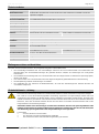
Haftungsausschluss und Restrisiken
Wir haften nicht für Schäden/Verluste, die auf folgende Ereignisse zurückzuführen sind:
Die zweckwidrige Installation bzw. den zweckwidrigen Gebrauch des Fan-Coil-Thermostats und insbesondere die
Nichtbeachtung der Sicherheitsanforderungen der geltenden Normen und/oder der Anweisungen des vorliegenden
Dokumentes.
Die Installation und Demontage des Fan-Coil-Thermostats ohne den nötigen Schutz vor elektrischen Spannungsspitzen,
Wasser oder Staub.
Den Gebrauch des Fan-Coil-Thermostats mit einem möglichen Zugriff auf gefährdete Bereiche ohne Werkzeug.
Die Manipulierung und/oder Veränderungen am Produkt .
Die Installation bzw. der Gebrauch mit Bedienelementen, die nicht den Anforderungen der aktuellen Normen und
Vorschriften entsprechen.
Sicherheitshinweis – Achtung
Der Einbau und die Montage elektrischer Geräte (Module) dürfen nur durch autorisiertes Fachpersonal erfolgen.
Das Gerät ist nur für die bestimmungsgemäße Verwendung vorgesehen. Ein eigenmächtiger Umbau oder eine
Veränderung sind verboten! Die Module dürfen nicht in Verbindung mit Geräten benutzt werden, die direkt oder
indirekt menschlichen, gesundheits- oder lebenssichernden Zwecken dienen oder durch deren Betrieb Gefahren für
Menschen, Tiere oder Sachwerte entstehen können. Der Anschluss von Geräten mit Stromanschluss darf nur bei
freigeschalteter Anschlussleitung erfolgen!
VORSICHT! Gefahr eines Stromschlages! Im Inneren des Gehäuses können sich spannungsführende Teile
befinden. Insbesondere bei Geräten im Netzspannungsbetrieb (normalerweise zwischen 90 und 265 V) kann
eine Berührung spannungsführender Teile Körperverletzungen zur Folge haben.
Ferner gelten
Gesetze, Normen und Vorschriften
Der Stand der Technik zum Zeitpunkt der Installation
Die technischen Daten sowie die Bedienungsanleitung des Gerätes
Seite wird geladen ...
Seite wird geladen ...
Seite wird geladen ...
Seite wird geladen ...
Seite wird geladen ...
Seite wird geladen ...
Seite wird geladen ...
Seite wird geladen ...
Seite wird geladen ...
-
 1
1
-
 2
2
-
 3
3
-
 4
4
-
 5
5
-
 6
6
-
 7
7
-
 8
8
-
 9
9
-
 10
10
-
 11
11
-
 12
12
-
 13
13
-
 14
14
-
 15
15
-
 16
16
-
 17
17
-
 18
18
-
 19
19
-
 20
20
-
 21
21
-
 22
22
-
 23
23
-
 24
24
-
 25
25
-
 26
26
-
 27
27
-
 28
28
-
 29
29


SystemAir TControl POD Bedienungsanleitung
- Typ
- Bedienungsanleitung
in anderen Sprachen
Verwandte Artikel

Andere Dokumente
-
Kampmann Klimaregler type 148941, 148942, 148943, 148944 Installationsanleitung
-
Mark PinTherm Connect Technical Manual
-
Grundig TB 7930 Datenblatt
-
-
-
Bticino KW4691 Benutzerhandbuch
-
Bticino 067459 Benutzerhandbuch
-
STIEBEL ELTRON LWZ 130 Enthalpie Operation Instruction
-
SBC PCD7.L60x-1 Room controller from FW SV2.13 Bedienungsanleitung
-
RADSON PTC BLOWER 950W Benutzerhandbuch