POLYTRON SPM 1000 digi PolyCompact base unit 10 module Bedienungsanleitung
- Typ
- Bedienungsanleitung

Bedienungsanleitung/
Operating manual
PolyCompact Kopfstelle
PolyCompact Headend
SPM 1000
0901096 V2.0

2
HINWEIS Der Inhalt dieses Firmenhandbuches ist urheberrechtlich geschützt und darf ohne Genehmigung des
Erstellers weder ganz noch teilweise in irgendeiner Form vervielfältigt oder kopiert werden. Änderun-
gen in diesem Firmenhandbuch, die ohne Zustimmung des Erstellers erfolgen, können zum Verlust
der Gewährleistung bzw. zur Ablehnung der Produkthaftung seitens des Herstellers führen.
Für Verbesserungsvorschläge ist der Ersteller dankbar.
Ersteller:
Polytron-Vertrieb GmbH
Postfach 10 02 33
75313 Bad Wildbad
Germany
Unten stehende Hervorhebungen werden in diesem Handbuch mit folgenden Bedeutungen verwendet:
HINWEIS gilt für technische Erfordernisse, die der Benutzer der Geräte besonders beachten muss, um eine
einwandfreie Funktion der Geräte/Anlage zu gewährleisten.
ACHTUNG bezieht sich auf Anweisungen, die genau einzuhalten sind, um Beschädigung oder Zerstörung des
Gerätes zu vermeiden.
VORSICHT steht für Anweisungen, deren Nichtbeachtung eine Gefährdung von Personen nicht ausschließt.
Bei Hinweisen auf ein durch eine Ortszahl versehenes Bauteil z.B. (Bild 1/3) bezieht sich in diesem Beispiel der
Hinweis auf Bild 1 Ortszahl 3.
Notes
The contents of this company manual are protected on copyright and may be quite still partly duplicated or copied
in any form without approval of the creator. Changes in this company manual which are carried out without consent
of the creator can lead to the loss of the guarantee or to the rejection of the product liability on the part of the
manufacturer.
The creator is grateful for suggestions for improvement.
Creator:
Polytron-Vertrieb GmbH
Postfach 10 02 33
75313 Bad Wildbad
Germany
The following emphases are used in this manual with the following meanings:
NOTE apply to technical requirements which the user of the equipment must particularly take into account
to ensure a faultless function of the equipment/plant.
ATTENTION refers to instructions which have to be adhered exactly to avoid damage or destruction of the device.
CAUTION stand for instructions endangering persons doesn't exclude whose nonobservance.
At references to a component e.g. (figure 1/3) provided by a place number the reference to picture 1 place num-
ber 3 refers in this example.

3
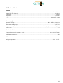
Inhaltsverzeichnis / Table of contents
1 Sicherheitsvorkehrungen ............................................................................................................................. 4
1.1 Hinweise zu Sicherheitsanforderungen an Antennenanlagen .................................................................... 5
2 Beschreibung .............................................................................................................................................. 6
3 Programmierung .......................................................................................................................................... 6
3.1 Programmieren von SAT-Eingangsfrequenzen .......................................................................................... 7
3.2 Programmieren von DVB-T-Eingangsfrequenzen....................................................................................... 7
3.3 Wiederherstellen der Grundeinstellung (Werkseinstellung) ........................................................................ 7
3.3.1 Programmablauf "Werkseinstellungen" ....................................................................................................... 7
3.4 Programmieren von Modulen ...................................................................................................................... 8
3.5 Programmieren der Daten über CopyKey ................................................................................................... 8
3.5.1 Programmablauf "CopyKey" ........................................................................................................................ 9
3.6 Software update SPM1000 digi durch Wechseln des EPROMs ............................................................... 10
4 Maße und Anschlusszeichnungen SPM1000 digi ..................................................................................... 11
5 Technische Daten ..................................................................................................................................... 12
6 Safety precautions ..................................................................................................................................... 13
6.1 References to safety requirements at antenna systems. .......................................................................... 14
7 Description................................................................................................................................................. 15
8 Programming ............................................................................................................................................. 15
8.1 Programming of SAT input frequencies .................................................................................................... 16
8.2 Programming of DVB-T- input frequencies ............................................................................................... 16
8.3 Activating the default setting (factory setting) ........................................................................................... 16
8.3.1 Program sequence "factory setting" .......................................................................................................... 16
8.4 Programming of Modules .......................................................................................................................... 17
8.5 Programming data using the CopyKey ..................................................................................................... 17
8.5.1 Program sequence "CopyKey" .................................................................................................................. 18
8.6 Software update SPM1000 digi by changing the EPROM ........................................................................ 19
9 Dimensions and Connection drawings SPM1000 digi .............................................................................. 20
10 Technical Data .......................................................................................................................................... 23
11 Assembly ................................................................................................................................................... 21
11.1 19"-Montage / Installation in a 19" rack ..................................................................................................... 21
11.2 Wandmontage / Wall mounting ............................................................................................................... 21
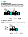
12 Anlagenbeispiele / Plant examples ........................................................................................................... 22
12.1 Aufbereitung von 20 Programmen von 2 Satelliten / Preparing of 20 programs of 2 satellites ............... 22
12.2 Kombination mit zwei Überwachungskameras / Combination with two monitoring cameras ................... 22
Deutsch
English
Deutsch
English

4
1 Sicherheitsvorkehrungen
Vor dem Arbeiten am Grundgerät SPM1000 digi bitte unbedingt die Sicherheitsbestimmungen sorgfältig le-
sen!
ACHTUNG Das Öffnen des Gerätes sollte nur von autorisiertem Fachpersonal durchgeführt wer-
den. Vor Beginn der Servicearbeiten das Gerät von der Spannungsversorgung trennen, da beim
Öffnen des Gehäuses spannungsführende Teile freigelegt werden, die bei Berührung lebensgefähr-
lich sein können. Zum Aus- und/oder Einbau eines Moduls muss das Grundgerät immer stromlos
sein!
Netzanschluss und Netzkabel
Das Gerät darf nur an einem Stromnetz mit einer Spannung zwischen 190 ... 250 V~ (50/60 Hz) betrieben werden.
Anschlusskabel
Anschlusskabel immer stolperfrei verlegen!
Erdung der Anlage
Nach den EN 50 083 / VDE 0855 Bestimmungen muss die Satellitenanlage den Sicherheitsbestimmungen wie z.B.
Erdung, Potenzialausgleich, etc. entsprechen.
Feuchtigkeit und Aufstellungsort
Das Gerät darf nicht Tropf- oder Spritzwasser ausgesetzt werden. Bei Kondenswasserbildung unbedingt warten,
bis das Gerät wieder trocken ist.
Umgebungstemperatur und Hitzeeinwirkung
Die Umgebungstemperatur darf +50 °C nicht überschre iten. Die Lüftungsschlitze des Gerätes dürfen auf keinen
Fall abgedeckt werden. Zu starke Hitzeeinwirkung oder Wärmestau beeinträchtigen die Lebensdauer des Gerätes
und können eine Gefahrenquelle sein.
Es darf nicht direkt über oder in der Nähe von Wärmequellen (z.B. Heizkörpern, Heizungsanlagen o.ä.) montiert
werden, wo das Gerät Hitzestrahlung oder Öldämpfen ausgesetzt ist.
Wegen der Brandgefahr durch Überhitzung oder Blitzeinschlag ist es empfehlenswert, das Gerät auf einer feuerfe-
sten Unterlage zu montieren.
Sicherungen
Sicherungen sollten nur von autorisiertem Fachpersonal gewechselt werden. Es dürfen nur Sicherungen des glei-
chen Typs eingesetzt werden.
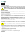
ACHTUNG Diese Baugruppe enthält ESD-Bauteile! (ESD = Elektrostatisch empfindliches Bauteil)
Eine elektrostatische Entladung, ist ein elektrischer Stromimpuls, der ausgelöst durch große Span-
nungsdifferenz auch über ein normalerweise elektrisch isolierendes Material fließen kann.
Um die Zuverlässigkeit von ESD-Baugruppen gewährleisten zu können, ist es notwendig, beim Umgang damit die
wichtigsten Handhabungsregeln zu beachten:
Elektrostatisch empfindliche Baugruppen dürfen nur an elektrostatisch geschützten Arbeitsplätzen (EPA) ver-
arbeitet werden!
Auf ständigen Potenzialausgleich achten!
Personenerdung über Handgelenk- und Schuherdung sicherstellen!
Elektrostatisch aufladbare Materialien wie normales PE, PVC, Styropor, etc. vermeiden!
Elektrostatische Felder >100 V/cm vermeiden!
Nur gekennzeichnete und definierte Verpackungs- und Transportmaterialien einsetzen!
Schäden durch fehlerhaften Anschluss und/oder unsachgemäße Handhabung sind von jeglicher Haftung
ausgeschlossen.
Deutsch

5
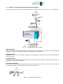
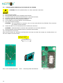
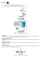
1.1 Hinweise zu Sicherheitsanforderungen an Antennenanlagen
Ihre Antennenanlage muss den Sicherheitsanforderungen nach EN 50 083 / VD 0855 Teil 10, 11, 12 entsprechen.
Bild 1 Verdrahtung der Antennenanlage
Denken Sie daran:
Wegen Brandgefahr durch Blitzeinschlag ist es empfehlenswert, alle metallischen Teile auf einer nicht brennbaren
Unterlage zu montieren. Brennbar sind Holzbalken, Holzbretter, Kunststoffe etc.
Kopfstation erden
Kopfstation über die an der Rückseite angebrachte Erdungsklemme gemäß Bild 1 mit der Potenzialausgleich-
schiene verbinden.
Koaxialkabel erden
Den weißen PVC-Außenmantel des Koaxialkabels im Bereich der Klemme entfernen. Abisoliertes Kabel in den Er-
dungsstreifen gemäß Bild 1 einklemmen.
F-Stecker aufschrauben
F-Typ-Stecker auf das abisolierte Koaxialkabel (z.B. IK 16) aufschrauben. Achten Sie darauf, dass die Abschir-
mung (Bild2/2) mit dem Innenleiter (Bild2/1) keinen Kurzschluss bildet.
Bild 2 Koaxialkabel konfektionieren
2
1
90

6
2 Beschreibung
Die von Polytron neuentwickelte PolyCompact-Kopfstelle SPM1000 digi ist eine kompakte, modulare Kanalaufbe-
reitung für kleine und mittlere Gemeinschaftsanlagen und wartet mit einer Vielzahl von Vorzügen auf.
Das sind:
Kompakte Bauweise,
einfache Bedienbarkeit,
flexibel durch verschiedene Module,
hoher Ausgangspegel,
durchgängiger Ausgangsfrequenzbereich (47 ... 860 MHz),
und
Testausgang (-20 dB)
Abhängig vom eingebauten Modul können die TV-Standards B/G, B/B, D/K, I, M/N, L eingestellt werden.
Die PolyCompact SPM 1000 digi ermöglicht eine qualitativ hochwertige und wirtschaftlich effektive Aufbereitung
von TV- und Radiokanälen.
Die Grundeinheit hat zehn Steckplätze und kann so bis zu 10 bzw. 20 Kanäle verarbeiten.
Für alle Empfangsmöglichkeiten von Satelliten- und terrestrischen Signalen (digital und analog) ebenso wie zur
Einspeisung und Modulation von Video- und Audiosignalen, sind entsprechende Module im Polytron-
Lieferprogramm erhältlich. Die Energieversorgung, eine Programmiereinheit für die einzelnen Empfangsmodule
sowie ein Ausgangssammelfeld sind in das Gerät integriert. Der ebenfalls integrierte Breitbandverstärker sorgt für
einen Ausgangspegel von maximal 100 dBµV.
Bei Bedarf lassen sich mehrere Basisgeräte problemlos kombinieren. Auf diese Weise können auch größere
Empfangsanlagen realisiert werden.
Das Gehäuse der Kopfstelle ist für die Installation in 19“-Schränken oder alternativ für die Befestigung an der Wand
ausgelegt.
ACHTUNG Bei der Installation der Kopfstelle ist darauf zu achten, dass die beiden Lüfterauslässe im Boden frei
bleiben. Ein Abdecken der Auslässe kann zu einem Hitzestau und dadurch zu einer Beschädigung der
Kopfstelle bzw. einzelner Module führen.
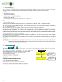
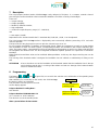
3 Programmierung
Die Tasten , , und (Bild 3/1) dienen zur Anwahl und Bestätigung der Bedienschritte und zum Einstel-
len der Werte.
Nach dem Einschalten (anschließen an das Netz) der
SPM1000 digi werden die Daten eingelesen und eingestellt.
Dieser Vorgang kann bis zu 15 Sekunden dauern.
Auf dem Display erscheint
Polytron Headend Loading Data...
und danach
Polytron Headend SPM1000 DIGI X.X
(X.X = Versions-Nr. der Software).
Nun befindet sich das Gerät im Standby-Modus.
Nach einem Netzausfall bleiben alle Daten erhalten.
Einschalten
lädt die Daten aus
dem Speicher
Standby-Modus,
Anzeige der Sof
t-
wareversion
Polytron Headend
SPM1000 DIGI A.7
Polytron Headend
Loading Data...

7
3.1 Programmieren von SAT-Eingangsfrequenzen
Als Eingangsfrequenz der SAT-Module wird die Differenz aus Transponderfrequenz
und Oszillatorfrequenz des LNBs und nicht die Transponderfrequenz programmiert.
Die Berechnung der SAT-ZF-Frequenz aus der Transponderfrequenz geschieht wie in
folgendem Beispiel:
Beispiel: Low Band
11406 MHz - 9750 MHz = 1656 MHz
Transponder - LO-LNB* = SAT-ZF
Beispiel: High Band
12480 MHz - 10600 MHz = 1880 MHz
Transponder - LO-LNB* = SAT-ZF
*
LO-LNB = Lokaloszillatorfrequenz des LNB-Konverters
3.2 Programmieren von DVB-T-Eingangsfrequenzen
Als Eingangsfrequenz wird die Kanalmittenfrequenz und nicht wie im analogen terre-
strischen Bereich der Bildträger programmiert.
Beispiel:
Kanal Bandbreite Kanalmittenfrequenz
Kanal 24 = 494 … 502 MHz = 498 MHz
Bild 3 Bedienteil
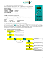
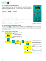
3.3 Wiederherstellen der Grundeinstellung (Werkseinstellung)
Im Standby-Modus die Taste drücken, bis die Anzeige Program/Service erscheint. Nun gemäß nachfolgen-
den Programmschritten die Werkseinstellung übernehmen. Es werden jetzt die Funktionen des SPM-1000 digi
überprüft und die werkseitigen Grundeinstellungen wieder hergestellt. Die Routine ist abgeschlossen, wenn der
Standby-Modus auf den das Gerät automatisch zurückspringt, wieder angezeigt wird.
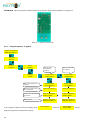
3.3.1 Programmablauf "Werkseinstellungen"
1
1
Standby-Modus
Umschalten auf Service
Polytron Headend
SPM1000 DIGI A.7
←
Reset
→
↨
Copykey
→ Service
↨ Program
→ Program
↨ Service
Auswahl
Reset
Standby-Modus
Anzeige der Softwareve
rsion
Wiederherstellung der Werk-
seinstellung
Werkseinstellung
wi
ederherstellen?
Neustart, lädt die Daten aus
dem Speicher
Restore Defaults
←
Yes
→
Restoring
Factory Settings
Polytron Headend
SPM1000 DIGI A.7
Polytron Headend
Loading Data...

8
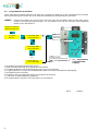
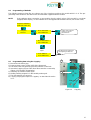
3.4 Programmieren von Modulen
Unten stehendes Programm zeigt wie man einen der 10 Plätze und damit das in ihm steckende Modul auswählt.
Die Programmierung des Moduls wird in der dem Modul beiliegenden Dokumentation beschrieben.
HINWEIS Erkennt die Software ein neues Modul nicht, dann wird der Steckplatz dieses Moduls beim durch-
scrollen nicht angezeigt (übersprungen), d.h. die Software muss auf den neuesten Stand upgedated
werden (siehe Abschnitt 3.6).
3.5 Programmiere
n der Daten über
CopyKey
1) Kopfstelle ausschalten (Netzstecker ziehen).
2) Drei Schrauben (Bild 4/3) der Frontblende herausdrehen.
3) Frontblende (Bild 4/2) mit der Bedieneinheit nach vorne herausnehmen.
4) CopyKey (Bild 4/1) von oben auf die Kontaktleiste (Bild 5/1) stecken (Steckposition gleichgültig).
5) Kopfstelle wieder einschalten.
6) Warten bis sich das Programm wieder im Standby-Modus befindet.
7) Jetzt kann die Datenübertragung beginnen.
8) Programmablauf "CopyKey" wie in Abschnitt 3.5.1 durchführen.
Bild 4 CopyKey
bis
Werte des ausgesuchten
Moduls können hier einge-
stellt werden.
Rolliert von Platz 10/ Platz 01
zum Anfang Platz 01/Platz 02.
→ Program
↨ Service
Polytron Headend
SPM1000 DIGI A.7
←
PL02 SPM-MMT →
↨ PL03 SPM-PST
←
PL10 SPM-TT →
↨ PL01 SPM-MST
←
PL01 SPM-MST →
↨ PL02 SPM-PTT
2
1
3

9
ACHTUNG Vor Aufstecken des CopyKeys immer die Kopfstelle ausschalten (Netzstecker ziehen).
Bild 5 CopyKey-Kontaktleiste
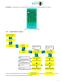
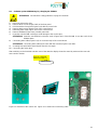
3.5.1 Programmablauf "CopyKey"
Ist kein Copykey aufgesteckt, dann erscheint statt die Anzeige und das
Programm springt auf die vorhergehende Anzeige zurück.
1
←
Copykey
→
↨
Reset
Polytron Headend
SPM1000 DIGI A.7
←
Reset
→
↨
Copykey
Reading Data
from Copykey
→ Service
↨ Program
←
Import Data
→
↨
Export Data
Polytron Headend
SPM1000 DIGI A.7
Polytron Headend
Loading Data...
→ Program
↨ Service
Standby-Modus
Neustart, lädt die Daten aus
dem Speicher
CopyKey von der Kontakt-
leiste abziehen.
Datentransfer von/zum Co-
pyKey.
Daten werden vom
CopyKey herunter-
geladen.
Daten werden auf
dem CopyKey ge-
speichert.
→
Copykey
↨
Reset
←
Export Data
→
↨
Import Data
Remove Copykey
Writing Data
to Copykey
Polytron Headend
SPM1000 DIGI A.7
Polytron Headend
Loading Data...
Remove Copykey
←
Import Data
→
↨
Export Data
No Copykey!

10
3.6 Software update SPM1000 digi durch Wechseln des EPROMs
ACHTUNG: ESD-Sicherheitsrichtlinien von Seite 4 Abschnitt 1 beachten!
1) Den Netzstecker ziehen.
2) Drei Schrauben (Bild 4/3) der Frontblende herausdrehen.
3) Frontblende (Bild 4/2) mit der Bedieneinheit nach vorne herausnehmen.
4) Die beiden Schrauben (Bild 6/1) des Kontrollboards lösen.
5) Datenkabel (Bild 7/1) des Kontrollboards abziehen.
6) E-Prom (Bild 8/1) vorsichtig abziehen (nicht verkanten!).
7) Das neue EPROM einsetzten.
ACHTUNG: Das neue EPROM so einsetzen, dass sich die Kerbe (Bild 8/2) des EPROMs über der Kerbe
des EPROM-Sockels befindet!
8) Datenkabel (Bild 7/1) auf Steckerleiste des Kontrollboards aufstecken.
ACHTUNG: Datenkabel (Bild 7/1) mit der roten Ader (Bild 7/2) nach unten aufstecken.
9) Displayfrontplatte mit Kontrollboard wieder am Gehäuse festschrauben.
10) Den Netzstecker einstecken.
Nach dem Einschalten der Kopfstelle und Übernahme der Daten erscheint die Anzeige des Standby-Modus und
die neue Software-Versionsnummer.
Bild 6 Rückseite Bedieneinheit Bild 7 Verbindungskabel Kontrollboard Bild 8 Kontrollboard
1
2
1
1
2
Polytron Headend
SPM1000 DIGI A.7
Software-Version

11
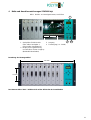
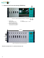
4 Maße und Anschlusszeichnungen SPM1000 digi
Bild 9 Bedien- und Anzeigeelemente, Anschlüsse
Bemaßung der Montagewinkel
Der Netzanschluss 230 V~ befindet sich auf der Rückseite der Grundeinheit.
1
3
2
4
406
mm
101
mm
1 Steckplätze für die Module 3 Ausgang
(links außen Steckplatz 1 4 Testausgang (ca. -20 dB)
rechts außen Steckplatz 10)
2 Display für Programmierung
und Anschluss für den CopyKey
(Bedienfeld abnehmbar)

12
5 Technische Daten
Ausgang
Frequenzbereich.....................................................................................................................................47 ... 862 MHz
Ausgangspegel bei 10 Kanälen......................................................................................................................100 dBµV
Anschlüsse....................................................................................................................................................F-Buchsen
Impedanz ...........................................................................................................................................................75 Ohm
1 x .............................................................................................................................................................. HF-Ausgang
1 x ...................................................................................................................................................Messbuchse -20 dB
Stromversorgung
Betriebsspannung...................................................................................................................180 … 265 V~, 50/60 Hz
Leistungsaufnahme.....................................................................................................................................max. 115 W
LNC-Fernspeisepannung Eingang.....................................................................................................................13,5 V=
Strom für die LNCs ........................................................................... max. 250 mA je Eingang / insgesamt max. 0,4 A
Schutzklasse.................................................................................................................................................................II
Mechanische Daten
Rahmengehäuse mit Deckel (B x H x T) .......................................................................................433 x 244 x 177 mm
Steckplätze.......................................................................................................................................10 Einschübe max.
Schutzgrad.............................................................................................................................................................IP 40
Sonstiges
Umgebungstemperatur.............................................................................................................................-10 ... +50 °C
Lagertemperatur .......................................................................................................................................-25 ... +75 °C

13
6 Safety precautions
Before working on the basic equipment SPM1000 digi please read the following safety precautions and the
safety precautions of the basic equipment carefully!
ATTENTION The unit should only be opened by qualified persons. The unit must be disconnected
from its power supply before service work is carried out. When the unit is open parts may be acces-
sible through which dangerous voltages flow and with which contact may endanger your life.
For removement and/or installation of a module the basic equipment must always be current less!
Mains connection and mains cable
Only operate the device at the specified voltage between 190 ... 250 V~ (50/60 Hz).
Connection cable
Lay cables so that they cannot be tripped over!
Earthing of the system
According to the regulations EN 50 083 / VDE 0855 the satellite plant must correspond to the safety regulations
e.g. grounding, potential equalization, etc.
Humidity and place of assembly
The equipment may not be exposed dripping or splash-water.
Waiting absolutely at condensed water formation until the device is dry again.
Ambient temperature and influence of heat
The ambient temperature must not exceed +50 °C.
In no case the louvers of the device may be covered off. To strong heat effect or accumulation of heat impairs the
life span of the equipment and can be a source of danger.
In no case the louvers of the base unit may be covered up. To strong heat effect or accumulation of heat impairs
the life span of the equipment and can be a source of danger.
It must not be installed directly over or in the immediate vicinity of heat sources (e.g. heating elements, heating
systems or similarly.), where the equipment is exposed to heat radiation or oil vapour.
Due to the risk of fire by overheating or lightning strike it is recommendable to install the equipment on a non-
combustible base.
Fuses
Fuses should be changed only from authorized technical personnel. Only fuses of the same type may be used.
ATTENTION This unit is equipped with ESD-components! (ESD = Electrostatic Sensitive De-
vice) An electrostatic discharge, is an electrical current pulse, which can flow triggered by large ten-
sion difference also over a normally electrically isolating material.
In order to be able to ensure the reliability of ESD assemblies, it is necessary to adhere the most important
handling rules:
Electrostatically sensitive assemblies may be processed only on electrostatically protected work place (EPA)!
Pay attention to permanent potential compensation!
Guarantee person grounding over wrist and shoe grounding!
Avoid electrostatically rechargeable materials like normal PE, PVC, polystyrene, etc.!
Avoid electrostatic fields >100 V/cm!
Use only labeled and defined packing and transportation materials!
Damages by faulty connection and/or inexpert handling are excluded from any liability.
English

14
6.1 References to safety requirements at antenna systems.
Your antenna system must comply with EN 50 083 / VD 0855 part 10, 11, 12.
Figure 10 Wiring of the antenna system
Remember:
Due to the risk of fires caused by lightning strikes, all metal parts must be mounted on a non-combustible base.
Combustible materials include wooden beams and boards, plastic boards etc.
Earthing the Headend Station
Earth the Headend Station by connecting the earth terminals on the back to the equipotential bonding rail as shown
in Figure 13.
Earthing Coaxial Cables
Remove the insulation of the coaxial cable near the terminal. Clamp the stripped cable in the earth strip as shown
in Figure 13.
Fitting F-Connectors
Screw the F-connector onto the stripped coaxial cable.(e.g. IK 16). Take care that the shielding (Figure 14/2) and
the inner core (Figure 14/1) may not form a short circuit.
Figure 11 Manufacturing Coaxial cables
2
1
90
Earth strip ES-06
Reflector Aerial

15
7 Description
The PolyCompact headend station SPM1000 digi, newly designed of Polytron, is a compact, modular channel
processing for small and medium-sized communal installations and offers a variety of advantages.
These are:
compact design,
simple operability,
flexible by different modules,
high outputlevel,
continuous output frequency range (47 ... 860 MHz),
and
test output (-20 dB)
Dependent on the inserted module the TV standards B/G, B/B, D/K, I, M/N, L can be adjusted.
The PolyCompact SPM 1000 digi makes a high-quality and economically effective processing of TV and radio
channels possible.
The base unit has ten plug-in places and can process channels up to 10 or 20.
For all reception possibilities of satellites and terrestrial signals (digital and analogous) as well as for the feeding
and modulation of video and audio signals, corresponding modules are available in the Polytron-delivering pro-
gram. The power supply, a programming unit for the individual receipt modules as well as an output collecting field
are integrated into the base unit. The also integrated broadband amplifier provides an output level of maximum
100 dBµV.
When required several base units can be combined without problems. In this way also larger receiving sets can be
realized.
The housing of the headend station is designed for installation into 19"-cabinets or alternatively for fixing on the
wall.
ATTENTION It has to be taken care at the installation of the headend station that the ventilation slots in the top
and in the base remain free. A covering of the outlets can lead to a damage of the headend station
and/or of individual modules.
8 Programming
The buttons , , and (Figure 15/1) are used for the selection and confirmation of the operating steps
and for adjusting the values.
After switching on (connecting to the mains) the SPM1000 digi,
the data are read in and adjusted.
This procedure can last up to 15 seconds.
On the display appears
Polytron Headend Loading Data...
and after this
Polytron Headend SPM1000 DIGI X.X
(X.X = version no. of the software).
The device is now in the standby mode.
After a power failure all data remain.
Einschalten
loads the data
from the memory
Standby mode,
Shows the soft-
ware version
Polytron Headend
SPM1000 DIGI A.7
Polytron Headend
Loading Data...
Switching on

16
8.1 Programming of SAT input frequencies
As input frequency of the SAT modules the difference from transponder frequency and
oscillator frequency of the LNBs and not the transponder frequency has to be pro-
grammed.The calculation of the SAT IF-frequency from the transponder frequency
happens as in the following example:
Example: Low Band
11406 MHz - 9750 MHz = 1656 MHz
Transponder - LO-LNB* = SAT-IF
Example: High Band
12480 MHz - 10600 MHz = 1880 MHz
Transponder - LO-LNB* = SAT-IF
*
LO-LNB = local-oscillator frequency of the LNB-converter
8.2 Programming of DVB-T- input frequencies
As input frequency the channel center frequency is to be programmed and not the
video carrier as in the analogous terrestrial range.
Example:
Channel band width channel center frequency
Channel 24 = 494 … 502 MHz = 498 MHz
Figure 12 Control Unit
8.3 Activating the default setting (factory setting)
Pressing the button in the standby mode, until the display shows Program/Service. Restoring factory settings
in accordance with the following program steps now. The functions of the SPM-1000 digi are now checked and the
factory settings restored. The routine is completed if the headend jumps back again in the standby mode automati-
cally, shown in the display.
8.3.1 Program sequence "factory setting"
1
1
Standby mode
Changeover to service
Polytron Headend
SPM1000 DIGI A.7
←
Reset
→
↨
Copykey
→ Service
↨ Program
→ Program
↨ Service
Reset selected
Standby mode
Shows the software version
Factory settings will be re-
stored
Restoring factory settings?
Restart, loads the data from
the memory
Restore Defaults
←
Yes
→
Restoring
Factory Settings
Polytron Headend
SPM1000 DIGI A.7
Polytron Headend
Loading Data...

17
8.4 Programming of Modules
The following program shows like one selects one of the 10 places and thus the module which is in it. The pro-
gramming of the module is described in the documentation supplied with the module.
NOTE If the software doesn't recognize a new module, then the plug-in place of this module is not shown
(skipped) at the display, i.e. the software has to be upgraded to the latest version (see section 10.6).
8.5 Programming data using the CopyKey
1) Disconnect the mains plug.
2) Remove three screws (Figure 16/3) of the front panel.
3) Pull forward the front panel (Figure 16/2) with the control unit.
4) Insert the CopyKey (Figure 16/1) from above onto the contact strip
(Figure 17/1) (Position unimportant).
5) Switching on headend station again.
6) Waiting until the program is in the standby mode again.
7) The data transfer can start now.
8) Carrying out program sequence "CopyKey" as described in section
3.5.1.
Figure 13 CopyKey
up to
Values of the selected
module can be pro-
grammed here.
Scrolling from PL10/PL01 to
the beginning PL01/PL02.
→ Program
↨ Service
Polytron Headend
SPM1000 DIGI A.7
←
PL02 SPM-MMT →
↨ PL03 SPM-PST
←
PL10 SPM-TT →
↨ PL01 SPM-MST
←
PL01 SPM-MST →
↨ PL02 SPM-PTT
2
1
3

18
ATTENTION Always turning the headend station off (pull power plug) before putting the CopyKeys on.
Bild 14 CopyKey-contact strip
8.5.1 Program sequence "CopyKey"
If no CopyKey is attached, then the display shows instead of and the
program jumps back to the previous display.
←
Copykey
→
↨
Reset
Polytron Headend
SPM1000 DIGI A.7
←
Reset
→
↨
Copykey
Reading Data
from Copykey
→ Service
↨ Program
←
Import Data
→
↨
Export Data
Polytron Headend
SPM1000 DIGI A.7
Polytron Headend
Loading Data...
→ Program
↨ Service
Standby-mode
Restart, loads the data from
the memory
Removing CopyKey from
the contact strip.
Data transfer from/to the
CopyKey.
Data are down-
loaded by the
CopyKey.
Data are stored on
the CopyKey.
→
Copykey
↨
Reset
←
Export Data
→
↨
Import Data
Remove Copykey
Writing Data
to Copykey
Polytron Headend
SPM1000 DIGI A.7
Polytron Headend
Loading Data...
Remove Copykey
←
Import Data
→
↨
Export Data
No Copykey!
1

19
8.6 Software update SPM1000 digi by changing the EPROM
ATTENTION: Consider ESD safety guidelines of page 16 section 8!
1) Disconnect the mains plug.
2) Remove three screws (Figure 16/3) of the front panel.
3) Pull forward the front panel (Figure 16/2) with the control unit.
4) Remove both screws (Figure 18/1) of the control board.
5) Removing data cable (Figure 19/1) of the control board.
6) Remove EPROM (Figure 20/1) carefully (don't tilt).
7) Insert the new EPROM carefully to avoid damage to the contact pins.
ATTENTION: Insert the new EPROM so that the notch (Figure 20/2) of the EPROM is over the notch of the
EPROM base!
8) Connecting data cable (Figure 19/1) on connector strip of the control board.
ATTENTION: Connecting data cable (figure 19/1) with the red wire (Figure 19/2) down.
9) Screwing front panel with control board onto the case again.
10) Connecting the mains plug.
After switching on the headend and take-over of the data the display shows the stand-by mode and the new soft-
ware version number.
Figure 15 Backside of the control unit Figure 16 Control board connecting cable Figure 17 Control board
1
2
1
1
2
Polytron Headend
SPM1000 DIGI A.7
Software-Version

20
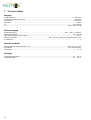
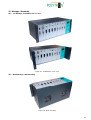
9 Dimensions and Connection drawings SPM1000 digi
Figure 21 Control- and Display elements, connections
Figure 22 Dimensions for the fixing brackets
The mains connection 230 V~ is on the back of the base unit
1
34
406
mm
101
mm
1 Module slots 3 Output
(left side module slot 1 4 Test output (approx. -20 dB)
right side module slot 10)
2 Display for programming
and connection for CopyKey
(Control panel removable)
2
Seite wird geladen ...
Seite wird geladen ...
Seite wird geladen ...
Seite wird geladen ...
-
 1
1
-
 2
2
-
 3
3
-
 4
4
-
 5
5
-
 6
6
-
 7
7
-
 8
8
-
 9
9
-
 10
10
-
 11
11
-
 12
12
-
 13
13
-
 14
14
-
 15
15
-
 16
16
-
 17
17
-
 18
18
-
 19
19
-
 20
20
-
 21
21
-
 22
22
-
 23
23
-
 24
24


POLYTRON SPM 1000 digi PolyCompact base unit 10 module Bedienungsanleitung
- Typ
- Bedienungsanleitung
in anderen Sprachen
Verwandte Artikel
-
POLYTRON SPM 2.000.. PolyCompact base unit 10 module Bedienungsanleitung
-
-
-
-
-
-
-
-
-