POLYTRON SPM-100 PolyCompact base unit for one module Bedienungsanleitung
- Kategorie
- Ladegeräte
- Typ
- Bedienungsanleitung
Seite wird geladen ...

2
HINWEIS
Der Inhalt dieses Firmenhandbuches ist
urheberrechtlich geschützt und darf ohne
Genehmigung des Verfassers weder
ganz noch teilweise in irgendeiner Form
vervielfältigt oder kopiert werden. Ände-
rungen in diesem Firmenhandbuch, die
ohne Zustimmung des Verfassers erfol-
gen, können zum Verlust der Gewähr-
leistung bzw. zur Ablehnung der Pro-
dukthaftung seitens des Herstellers füh-
ren. Für Verbesserungsvorschläge ist
der Verfasser dankbar.
Verfasser:
Polytron-Vertrieb GmbH
Postfach 10 02 33
75313 Bad Wildbad
Germany
Unten stehende Hervorhebungen wer-
den in diesem Handbuch mit folgenden
Bedeutungen verwendet:
HINWEIS gilt für technische Erfor-
dernisse, die der Benutzer
der Geräte besonders be-
achten muss, um eine
einwandfreie Funktion der
Geräte/Anlage zu gewähr-
leisten.
ACHTUNG bezieht sich auf Anwei-
sungen, die genau einzu-
halten sind, um eine Be-
schädigung oder Zerstö-
rung des Gerätes zu ver-
meiden.
VORSICHT steht für Anweisungen,
deren Nichtbeachtung ei-
ne Gefährdung von Per-
sonen nicht ausschließt.
Bei Hinweisen auf ein durch eine Orts-
zahl versehenes Bauteil z.B. (Bild 1/3)
bezieht sich in diesem Beispiel der Hin-
weis auf Bild 1 Ortszahl 3.
NOTE
The contents of this company manual
are copyrighted and must not be dupli-
cated or copied in any form, either par-
tially or in full, without the prior consent
of the editor. Changes in this company
manual which are carried out without
consent of the creator can lead to the
loss of the guarantee or to the rejection
of the product liability on the part of the
manufacturer. The editor is grateful for
suggestions.
Editor:
Polytron-Vertrieb GmbH
Postfach 10 02 33
75313 Bad Wildbad
Germany
The following emphases are used in this
manual with the following meanings:
NOTE applies to technical re-
quirements which must
be taken into account to
ensure a faultless func-
tion of the device/plant.
ATTENTION refers to instructions
which have to be ad-
hered exactly to avoid
damage or destruction
of the device.
CAUTION applies to instructions
whose nonobservance
doesn't exclude the en-
dangering of persons.
At references to a component provided
by a place number (e.g. figure 1/3) the
reference corresponds to picture 1 place
number 3.

3
1 Sicherheitsvorkehrungen
Vor dem Arbeiten am Grundgerät SPM 100
bitte unbedingt folgende Sicherheitsbe-
stimmungen sorgfältig lesen!
ACHTUNG Das Öffnen des Gerätes
sollte nur von autorisiertem Fachpersonal
durchgeführt werden.
Zum Aus- und/oder Einbau eines Moduls
muss das Grundgerät immer stromlos
sein!
Anschlusskabel
Anschlusskabel immer stolperfrei verlegen!
Erdung der Anlage
Nach den EN 50 083 / VDE 0855 Bestim-
mungen muss die Satellitenanlage den Si-
cherheitsbestimmungen wie z.B. Erdung, Po-
tenzialausgleich, etc. entsprechen.
Feuchtigkeit und Aufstellungsort
Das Gerät darf nicht Tropf- oder Spritzwasser
ausgesetzt werden. Bei Kondenswasserbil-
dung unbedingt warten, bis das Gerät wieder
trocken ist.
Umgebungstemperatur und Hitzeeinwir-
kung
Die Umgebungstemperatur darf +50 °C nicht
überschreiten. Die Lüftungsschlitze des Gerä-
tes dürfen auf keinen Fall abgedeckt werden.
Zu starke Hitzeeinwirkung oder Wärmestau
beeinträchtigen die Lebensdauer des Gerätes
und können eine Gefahrenquelle sein.
Das Gerät darf nicht direkt über oder in der
Nähe von Wärmequellen (z.B. Heizkörpern,
Heizungsanlagen o.ä.) montiert werden, wo
das Gerät Hitzestrahlung oder Öldämpfen
ausgesetzt ist.
Wegen der Brandgefahr durch Überhitzung
oder Blitzeinschlag ist es empfehlenswert,
das Gerät auf einer feuerfesten Unterlage zu
montieren.
Sicherungen
Sicherungen sollten nur von autorisiertem
Fachpersonal gewechselt werden. Es dürfen
nur Sicherungen des gleichen Typs einge-
setzt werden.
1 Safety precautions
Before working on the base unit SPM 100
please read the following safety precau-
tions carefully!
ATTENTION The unit should only
be opened by qualified persons.
For removement and/or installation of a
module the base unit must always be
currentless!
Connection cable
Lay cables that they cannot be tripped over!
Grounding of the system
According to the regulations EN 50 083 / VDE
0855 the satellite plant must correspond to
the safety regulations e.g. grounding, poten-
tial equalization, etc.
Humidity and place of assembly
The equipment may not be exposed dripping
or splash-water. In case of condensed water
formation wait until the device is dry again.
Ambient temperature and influence of heat
The ambient temperature must not exceed
+50 °C. Don’t cover the louvers of the device.
To strong heat effect or accumulation of heat
impairs the life span of the equipment and can
be a source of danger.
The unit must not be installed directly above
or in the immediate vicinity of heat sources
(e.g. heating elements, heating systems or
similarly.), where the equipment is exposed to
heat radiation or oil vapour.
Due to the risk of fire by overheating or light-
ning strike it is recommendable to install the
equipment on a non-combustible base.
Fuses
Fuses should be changed only from author-
ized technical personnel. Only fuses of the
same type may be used.

4
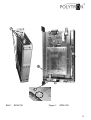
2 Beschreibung
Die Grundeinheit SPM 100 ist aus-
gelegt zur Aufnahme eines Moduls
der SPM-Serie. Sie ermöglicht die
einfache Erweiterung bestehender
Anlagen, oder kann als eigenständi-
ge Kopfstelle für 1 bzw. 2 Kanäle
eingesetzt werden. Zum Betrieb be-
nötigt man ein stabilisiertes Netzteil
(12 V/2,5 A), welches ebenfalls bei
Polytron erhältlich ist (NG12/3000).
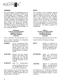
2.1 Einbau oder Wechseln ei-
nes Moduls
Zum Einbau oder Wechsel eines
Moduls die sechs Schrauben
(Bild 1/1) lösen und die linke Sei-
tenwand des Gehäuses abnehmen.
Das Modul in die Anschlussleiste
und HF-Buchse (Bild 1/2) ganz
hineindrücken.
Die linke Seitenwand wieder mit den
Kreuzschlitzschrauben und Unter-
legscheiben (Bild 1/1) befestigen.
2.2 LNB Versorgungsspannung
Im Auslieferungszustand wird keine
Versorgungsspannung an das LNB
weitergegeben.
Um Versorgungsspannung bei Be-
darf an das LNB weiterzuleiten,
muß die Lötstelle (Bild 1/3) gebrückt
werden.
2 Description
The basic unit SPM 100 is designed
for the installation of a module of the
SPM series. It allows the simple ex-
tension of existing installation or can
be used for 1 or 2 channels as an
independent headend. Only use the
appliance in combination with a sta-
bilized adapter plug (12 V/2,5 A),
which is also available at Polytron
(NG12/3000).
2.1 Installing a new module or
changing a module
For installing or changing a module
loosen the six cross-head screws
(Figure 1/1) and remove the left
cover of the case.
Install the module by pushing it into
the connection strip and the RF jack
(Figure 1/2).
Fastening the left cover with the
cross-head screws and washers
(Figure 1/1) again.
2.2 LNB voltage
In the delivery status no voltage is
given to the LNB.
To route voltage to the LNB if re-
quired, the soldering (Figure 1/3)
must be bridged.

5
Bild 1 SPM-100
Figure 1 SPM-100
2
1
3

6
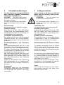
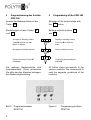
3 Programmierung des Gerätes
SPM 100
Anwahl der Bedienschritte mit der
Taste .
Einstellungen mit den Tasten
und .
Die weiteren Bedienschritte sind
modulspezifisch. Diese entnehmen
Sie bitte der den Modulen beiliegen-
den Bedienungsanleitung.
Bild 2 Programmiertasten
SPM 100
3 Programming of the SPM 100
Selection of the control steps with
the button.
Settings with the buttons
and .
All further steps are specific to the
various modules. We recommend to
read the separate guidelines of the
modules.
Figure 2 Programming buttons
SPM 100
+
-
OK
+
-
OK
.
S2.0
PL 01
Push key
M
to start the
menu
Anzeige im Standby modus
Taste
M
drücken um das
Menü zu starten
Durch drücken der Taste
M
bestätigen
Confirming by pressing the
button M
Shows software versionAnzeige der Softwareversion
Display in standby modus
M
M
M

7
4
Technische Daten SPM 100 4 Technical data SPM 100
Anzahl der Steckplätze / Number of plug-in places................................................1
Betriebsspannung / Operating voltage..................................................... +12 V DC
Betriebstemperatur / Operating temperature......................0 ... 50 °C / 32 ... 122 °F
Ausgangsbuchse / Output jack ..............................................................................F
Ausgangsimpedanz / Output impedance ......................................................... 75 Ω
Verstärkung / Gain......................................................................................... 10 dB
Maße (B x H x T) / Dimensions (W x H x D)..............................40 x 285 x 147 mm
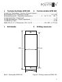
5
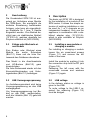
Bohrmaße 5 Drilling measures
Bild 3 Bohrmaße SPM 100 Figure 3 Drilling measures SPM 100
285 mm
269 mm
37 mm
40 mm

8
Polytron-Vertrieb GmbH
Postfach 10 02 33
75313 Bad Wildbad
Zentrale/Bestellannahme
H.Q. Order department + 49 (0) 70 81/1702 - 0
Technische Hotline
Technical hotline + 49 (0) 70 81/1702 - 12
Telefax + 49 (0) 70 81) 1702 - 50
Internet http://www.polytron.de
eMail info@polytron.de
Technische Änderungen vorbehalten
Subject to change without prior notice
Copyright © Polytron-Vertrieb GmbH
-
 1
1
-
 2
2
-
 3
3
-
 4
4
-
 5
5
-
 6
6
-
 7
7
-
 8
8


POLYTRON SPM-100 PolyCompact base unit for one module Bedienungsanleitung
- Kategorie
- Ladegeräte
- Typ
- Bedienungsanleitung
in anderen Sprachen
Verwandte Artikel
-
POLYTRON SPM 1000 Plus PolyCompact base unit 10 module Bedienungsanleitung
-
-
-
-
-
-
-
-
-