
FIBERMASTER
QUICK REFERENCE GUIDE
Depend On Us

2www.trend-networks.com 240810 Rev 1.
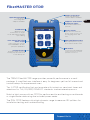
FiberMASTER OTDR
Quick Reference Guide
Guide de référence rapide
Bedienungsanleitung
Guía de referencia rápida
© TREND NETWORKS 2021
The information contained in this document is the property of TREND NETWORKS and is supplied without liability
for errors and omissions. No part of this document may be reproduced or used except as authorized by contract or
other written permission from TREND NETWORKS. The copyright and all restrictions on reproduction and use apply
to all media in which this information may be placed. TREND NETWORKS pursues a policy of continual product
improvement and reserves the right to alter without notice the specification, design, price or conditions of supply of
any product or service. All rights reserved.
Les informations dans ce document sont la propriété de TREND NETWORKS et elles sont fournies sans
responsabilité pour les erreurs et les omissions. Aucune partie de ce document ne doit être reproduite ou utilisée,
sauf en cas d’autorisation par contrat ou en cas d’autre autorisation écrite donnée par TREND NETWORKS Le
copyright et toutes les limitations concernant la reproduction et l’utilisation s’appliquent à tous les supports sur
lesquels cette information peut être placée. TREND NETWORKS améliore continuellement ses produits et se réserve
le droit de modifier sans préavis la spécification, la conception, le prix ou les conditions de fourniture d’un produit ou
d’un service. Tous droits réservés.
Die Informationen in diesem Dokument sind das Eigentum von TREND NETWORKS und werden ohne
Gewährleistung der Vollständigkeit oder Korrektheit gegeben. Dieses Dokument darf nur soweit vertraglich
oder anderweitig schriftlich von TREND NETWORKS Zugesichert ganz oder teilweise vervielfältigt werden. Das
Urheberrecht und alle Einschränkungen zur Vervielfältigung und Nutzung gelten für alle Datenträger, auf denen diese
Informationen gespeichert werden können. TREND NETWORKS bemüht sich um ständige Produktverbesserungen
und behält sich das Recht vor, die Spezifikation, das Design, den Preis oder die Lieferbedingungen jeglicher Produkte
oder Dienste ohne Vorankündigung zu ändern. Alle Rechte vorbehalten.
La información que figura en este documento es propiedad de TREND NETWORKS quien no asume responsabilidad
alguna sobre posibles errores u omisiones que puedan existir en este documento. Queda prohibida la reproducción
parcial o total de este documento, así como darle un uso distinto al autorizado mediante contrato o autorización
escrita por parte de TREND NETWORKS independientemente del formato y soporte de los contenidos. TREND
NETWORKS sigue una política de mejora continua del producto y nos reservamos el derecho de modificar sin previo
aviso las especificaciones, diseño, precio o condiciones de suministro de cualquier producto o servicio. Todos los
derechos reservados.
240810 Rev 1. 10/2021
TREND NETWORKS
Stokenchurch House
Oxford Road
Stokenchurch
High Wycombe
Buckinghamshire
HP14 3SX
United Kingdom
English
Deutsch
Français
Español

3
Depend On Us
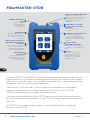
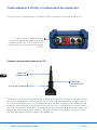
FiberMASTER OTDR
Auto Centre/Pass/fail
Video Scope
Video inspection system
with IEC61300-3-35 auto
pass/fail capabilities.
Optical Power Meter
Full range of
interchangeable
adapters available
Fault Locator Port
2.5mm standard with
1.25mm adapter available
Certification
OTDR for tier-2
Certification of single-
mode and Multimode fiber
optic cabling
Troubleshooting
Red Laser Light source to
visually pinpoint faults and
locate fiber ports
Supports all Common
Connector Types
SC Standard, FC and ST
optional
Map View/Fault Locator
Get a quick picture of your
fiber with the fault locator
PM and LS
Power meter and CW light
source function for use as
optical loss test set
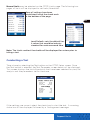
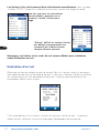
Device Setup
Upon first use, enter the
device setup screen to set
the language, date and
time.
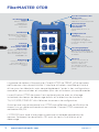
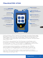
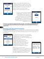
The TREND FiberMASTER range provides powerful performance in a small
package. A simplified user interface is easy for beginners yet has full manual and
custom setups for experienced users.
Tier 2 OTDR certification fast and accurate with instant-on, zero boot times and
selections for TIA/ISO/IEEE/CENELEC standards to eliminate setup errors.
Match a light source with an OTDR to perform end-to-end testing on multimode
or single-mode cable using the included power meter.
The PON OTDR features ultra-high dynamic range to measure 1:32 splitters for
installation testing and troubleshooting.
EN

4www.trend-networks.com 240810 Rev 1.
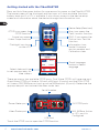
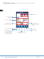
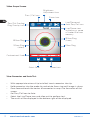
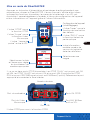
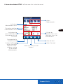
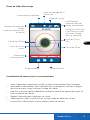
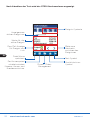
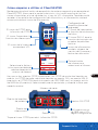
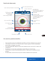
Touch language
button to select
language
Select date and time
to set appropriately for
time stamps
Map icon opens the
Fault Locator function
OTDR icon opens the
OTDR function
Information Icon;
model, firmware
version number and
Calibration date
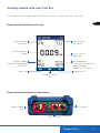
SM OTDR ports
Scope icon opens
Video Scope function
PM/LS icon opens the
Optical Loss Test Set
function
Flashlight icon turns
on the VFL
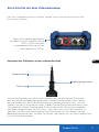
Device Setup (Gear Icon)
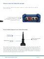
Video Probe port
USB Port
MM, 1625nm Active
or VFL port As
Configured
Serial Number
Power Meter port
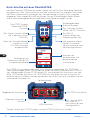
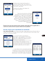
Getting started with the FiberMASTER
Press and hold the power button for one second to power on the FiberMASTER.
The home screen will be displayed and the icons will show available functions,
battery level and if a VFL is available. It also allows access to the device setup
screen and information about the device through the information icon.
There are one or two available OTDR ports. Dual Wave OTDRs will have one port,
Quad Wave OTDRs will have a SM and a MM port (2 ports) and the PON OTDR
will have a 1310/1550nm port and an active 1625nm port (2 ports). Determine the
appropriate port and connect the fiber under test.
Touch the OTDR icon to open the OTDR function.
EN

5
Depend On Us
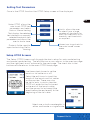
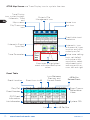
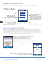
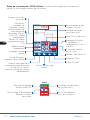
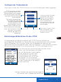
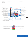
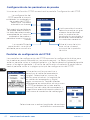
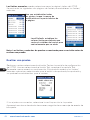
Setting Test Parameters
Once in the OTDR function the OTDR Setup screen will be displayed.
EN
Setup OTDR allows the
user to set OTDR test
parameters and select
Auto or Manual testing Limits allows the user
to select from a large
number of standards for
pass/fail thresholds or to
manually set thresholds
as required.
Test displays the selected
test standards or manually
selected thresholds, test
parameters and allows the
user to start a trace.
Use these check boxes to set the
launch or tail cable on or o.
Select the edit icons to input the
length of the launch and tail cables
as appropriate. These may also
be set to auto, in which case the
OTDR will establish the first event
as the end of the launch cable
and the second to last event (the
event before the end event) as the
beginning of the tail cable.
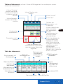
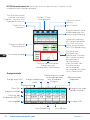
Setup OTDR Screens
The Setup OTDR Screens walk through the basic setup for auto mode testing
and manual mode testing. The left/previous arrow, returns to the previous page
and the right/next arrow, advances to the next page. The check box in the
bottom middle returns to the main OTDR Setup page.
Projects folder used to
open and existing file for
viewing
Home icon to go back to
the main home screen
menu
Select one or both wavelengths in
either multimode or single-mode.

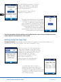
6www.trend-networks.com 240810 Rev 1.
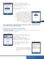
Enough information has now been
entered to conduct an Auto Test.
If Auto is selected, the averaging
time, range and pulse width will be
automatically set based on analysis
conducted by the OTDR. Select
Manual and those parameters
automatically set in Auto Mode will
be available for adjustment.
Setting Limits for Pass/Fail
Standard Limits are pre-set limits/thresholds against which the traces are
measured for pass/fail analysis to certify network links.
Manual allows for setting user
defined Pass/Fail thresholds
For the purposes of this quick start guide please select Auto followed by the
check box at the bottom of the screen.
Standard limits will be highlighted,
There are 5 pages of pre-set limits/
thresholds to which the test will be
measured to determine Pass/Fail.
The first page lists cabling
standards and pages 2-5 lists
application standards.
If a standard set of limits is
selected, when the check box
at the bottom of the display is
touched, a page confirming those
standards will be shown, such as
this sample page.
Set the Refractive Index if known.
Select Load Default if the index
of refraction (IOR) and/or helix
factor are unknown.
Set the End Of Fiber (EOF)
Detection Threshold.
EN

7
Depend On Us
Once all settings have been
established, touch the check mark
at the bottom of the page.
Manual limits may be selected on the OTDR Limits page. The following two
pages of limits will be displayed to set limits/thresholds.
Note: The Limits and test thresholds will be displayed for review prior to
taking a test.
Load Defaults sets the default lim-
it values that would be industry
standard for each measured item.
Take a trace by selecting the Test button on the OTDR Setup screen. Once
the Test button is selected, the Test Parameter screen below will be displayed.
This screen displays the limits/thresholds that have been selected for pass/fail
analysis and the parameters set for the trace.
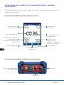
Conducting a Test
If the settings are correct, select the check box to start the test. A scanning
status bar will be displayed, followed by a finding event message.
EN

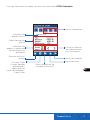
8www.trend-networks.com 240810 Rev 1.
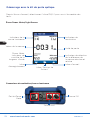
Active event
indicator
Data for active
event
Event and link
pass/fail indicator
Event icons
Use arrows to
move through
events
File/Trace save
Trace Display icon
cycles through;
Schematic, Trace
and Map views
Projects/File
Management icon
Home Icon
Test Icon
OTDR Schematic Screen will be displayed once the test is complete.
EN

9
Depend On Us
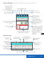
Dashed line
inactive cursor
Displays loss data
and touch area to
toggle through
2Point loss, Attn/
ORL, Avg. Loss
and LSA Loss
Event Reflectivity
A and B cursor
locations
Zoom adjustment
setting; X only,
Y only or both X
and Y
File/Trace save
Trace Display
icon, cycles through;
Schematic, Trace and
Map screens
Projects/File
Management icon
Home Icon
Test Icon
Solid line is active
cursor
Test Wavelength
Inset/see below
Distance and loss
per division
Inset
X/Y Zoom Factor
LSA splice setting
toggle Active cursor indicator
and selector
Snap to event with
Locked Cursors
Micro adjustments
for cursors
OTDR Trace Screen use Trace Display icon to cycle to the trace screen view.
EN

10 www.trend-networks.com 240810 Rev 1.
OTDR Map Screen use Trace Display icon to cycle to the view.
Schematic Event/
Span Map
Trace Parameters
Event map of highlighted
event with adjustable splice
zones
Event table inset
see below
Schematic icon
with event #, type,
location and color
coded pass/fail
File/Trace save
icon
Trace Display
icon, cycles through;
Schematic, Trace
and
Map screens
Projects/File
Management icon
Home Icon
Test Icon
Splice zone setting
tools, set default
with pulse width
association, select
adjustment point
and move with ar-
rows, left and right
Event Number
Pass/Fail Event Type or
Reflectance
Value
Link Information
Link Loss
EOF Event
Information
System ORL
Link dB Per/Km
Event Location Event Loss in dB
Loss Between
Previous and
Current Events
dB Per/Km
Between Events
Event Table
EN

11
Depend On Us
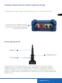
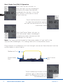
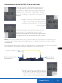
To operate the video scope, touch the Scope icon on the Home Screen.
Focus Ring
Adapter Tip
Getting started with the Video Inspection Scope
If a probe is not connected already,
connect the Video Inspection Probe
R240-VIP to the video probe port
on the top of the OTDR.
To remove a tip from the probe, grasp the probe tip and unscrew the tip
retention nut. As oriented in the picture; rotate left to loosen and right to
tighten the retention nut on the probe tip. Pull the tip straight up from the
probe. To place a tip on the probe, ensure the lens is clean, slide the tip on to
the end of the probe and tighten the tip retention nut. Do not over tighten the
retention nut.
Tip Retention Nut
Place proper tip on VIP
EN

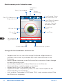
12 www.trend-networks.com 240810 Rev 1.
Brightness
Adjustment Icon
25um Ring
130um Ring
(Green)
250um Ring
120um Ring
(Yellow)
Pass / Fail Icon
Pass/Fail Grading
Ring Overlay Icon
Contaminant Scale
Quick Save
Live/Pause and
Auto Pass/Fail Icon
Live/Pause view
indication or name
of loaded file from
memory
Video Scope Screen
View Connector and Auto Test
• With appropriate universal tip installed, insert connector into tip.
• Hold connector into the probe tip and rotate focus ring until image is sharp.
• Once focused touch the center of connector to snap it to the center of the
screen.
• Set Pass/Fail Icon to Auto.
• Select the Live/Pause icon and allow unit to perform test.
• The result will be displayed in the bottom right of the displayed.
EN
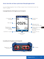
Home Icon
Zoom Icon

13
Depend On Us
Folder/Project
Icon
Modulation
indicator
Set Reference,
absolute and relative
measurement
selection indicator
Measurement
Value
Light Source
indicator
Power Meter
Control/Wavelength
indicator
Save Icon Home Icon
SM Source
Loss Unit of
Measure
Power Meter/Light Source Screen
Power Meter
Port
MM Source
Getting started with Loss Test Set
From the Home Screen select the PM/LS icon to open the Loss Test Set.
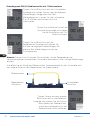
Power Meter/Light Source Connections
EN

14 www.trend-networks.com 240810 Rev 1.
Touch the Power Meter indicator to
show the power meter wavelengths
available and select the appropriate
wavelength for the test.
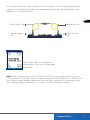
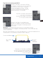
Reference Cord
Power Meter
Port
Light Source
Port
Plug one end of a reference cord into the light source and the other end into the
power meter as shown below.
Note: This step may be skipped as the power meter will set itself to the
appropriate wavelength, if it is being used with a compatible source.
Touch reference indicator in the
bottom right of the display and
select, Set Reference to zero out
the reference cord.
Touch the Modulation indicator
to open the modulation options
and set the modulation to CW for
continuous wave.
Touch the Source indicator to
show the light source wavelengths
available and select the desired
wavelength for the test. Allow the
light source 2-3 minutes to warm
up and stabilize.
Basic Single Cord PM/LS Operation
EN

15
Depend On Us
Fiber Under Test Reference Cord
Power Meter
Port
Light Source
Port
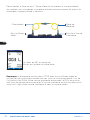
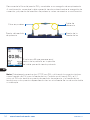
Note: This Example shows two OTDRs with PM and using the optical ports as
CW sources for the light source. When using stand alone PM and LS, the PM will
only have a single power meter port and the light source will have one or two
ports depending on whether it is a dual or quad wave light source.
Disconnect the fiber from the PM port and connect it to a mating sleeve, and
connect the cable/cord under test between the mating sleeve and the power
meter port, as shown below.
The value in dB, in the center of
the display is the loss of the cable
under test.
EN

16 www.trend-networks.com 240810 Rev 1.
FiberMASTER OTDR
Centrage
automatique/
Pass/Echec Video
Microscope
Système Video Microscope
avec capacités de PASS ou
Echec automatiques selon
l’IEC61300-3-35
Test de puissance
optique
Gamme complète
d’adaptateurs
interchangeables
disponibles
Port de localisation des
défauts VFL
Standard 2,5 mm avec
adaptateur 1,25 mm disponible
Certification
OTDR pour la certification
de niveau 2 des câblages
en fibre optique
monomode et multimode
Dépannage
Laser pour localiser les
ports Fibre Optique et
vérifier la continuité de la
lumière
Prend en charge
tous les types de
connecteurs
SC standard, FC et ST en
option
Vue cartographique/
localisateur de défauts
Obtenez une image rapide de
votre fibre avec le localisateur
de défauts
PM et LS
Fonction de mesure de
puissance et de source
lumineuse CW pour
une utilisation en tant
qu’ensemble de test de perte
optique
Configuration de
l’appareil
Lors de la première utilisation,
entrez dans l’écran de
configuration de l’appareil
pour définir la langue, la date
et l’heure
La gamme de testeurs fibre optique FiberMASTER de TREND, ore de hautes
performances dans de petit boîtier. L’interface utilisateur simplifiée est facile à
utiliser pour les débutants mais permet également l’accès à des configurations
manuelles personnalisées, et complètes pour des utilisateurs plus expérimentés.
La certification OTDR de niveau 2 est rapide et précise avec un allumage
instantané, des temps de démarrage réduits et la sélection de standards
TIA/ISO/IEEE/CENELEC afin d’éliminer les erreurs de configuration.
Associez une source lumineuse à un OTDR pour eectuer une certification de
niveau 1 sur un câble multimode ou monomode. Chaque OTDR comprend un
wattmètre MM/SM.
L’OTDR PON est doté d’une plage dynamique ultra élevée permettant de
mesurer facilement les répartiteurs 1:32 pour les tests d’installation et le
dépannage.
FR

17
Depend On Us
Sélectionnez une
langue
Sélectionnez la date
et l’heure pour régler
les horodateurs de
manière appropriée
L’icône Traces” ouvre la
fonction de localisation
des défauts
L’icône “OTDR” ouvre
la fonction OTDR
Icône Information :
modèle, numéro de
version du logiciel et
date de calibration
Ports SM OTDR
L’icône “Scope” ouvre
la fonction Video
Microscope
L’icône “PM/LS” ouvre
la fonction de test de
perte optique.
L’icône “lampe de
poche” active le VFL
Configuration de l’appareil
( icône Réglages)
Port du Video
Microscope
Port USB
Port MM, 1625nm
actif ou VFL
Numéro de série
Port du wattmètre
Mise en route du FiberMASTER
Appuyez sur le bouton d’alimentation et maintenez-le enfoncé pendant une
seconde pour allumer le FiberMASTER. L’écran d’accueil s’ache et les icônes
indiquent les fonctions disponibles, le niveau de la batterie et si un VFL est
disponible. Il permet également d’accéder à l’écran de configuration de l’appareil
et aux informations sur l’appareil grâce à l’icône d’information.
Il y a un ou deux ports OTDR disponibles. Les OTDR “DUAL” ont un port soit SM
ou MM, les OTDR “QUAD” ont un port SM et un port MM (2 ports) et le OTDR
PON a un port 1310/1550nm et un port actif 1625nm (2 ports). Déterminez le port
approprié et connectez la fibre à tester.
L’icône OTDR pour ouvrir la fonction OTDR.
FR

18 www.trend-networks.com 240810 Rev 1.
Réglage des paramètres de tests
Une fois dans la fonction OTDR, l’écran de configuration OTDR s’ache.
Réglages OTDR permet à
l’utilisateur de définir les
paramètres de l’OTDR et
de sélectionner les tests
automatiques ou ma-
nuels. Limites permet à
l’utilisateur de choisir
parmi un grand nombre
de normes L’icône
“Limites” pour valider les
tests Pass/Echec ou de
définir manuellement des
seuils selon les besoins.
L’Icône “Test” ache
les normes de test
sélectionnées ou les seuils
sélectionnés manuellement,
les paramètres de test et
permet à l’utilisateur de
démarrer un test.
Utilisez ces cases pour activer ou désactiver la
bobine d’amorce de début et de fin.
Sélectionnez les icônes edit pour saisir la
longueur de vos bobines amorces, Auquel
cas l’OTDR établit le premier événement
comme étant la fin de la bobine d’amorce
de début et l’avant-dernier événement
(l’événement précédant l’événement de
fin) comme étant le début de la bobine
d’amorce de fin.
Écrans de configuration de l’OTDR
Les écrans de configuration de l’OTDR permettent d’eectuer la configuration
de base pour les tests en mode automatique et en mode manuel. La flèche
gauche/précédente permet de revenir à la page précédente et la flèche droite/
suivante de passer à la page suivante. La case à cocher en bas au milieu permet
de revenir à la page principale de configuration de l’OTDR.
Icone “Dossiers” permet
d’ouvrir un fichier
existant pour le visualiser.
Icône Accueil pour
revenir au menu principal.
Sélectionnez une ou deux longueurs d’onde en
multimode ou en monomode.
FR

19
Depend On Us
Vous avez maintenant saisi
susamment d’informations pour
eectuer un test automatique. Si
vous sélectionnez Auto, le temps de
moyennage, la plage et la largeur
d’impulsion seront automatiquement
définis en fonction de l’analyse
eectuée par l’OTDR. Si vous
sélectionnez Manuel, vous pourrez
régler les paramètres selon vos
exigences de tests.
Réglage des limites de réussite/échec
Les limites standards sont des limites/seuils prédéfinies par rapport aux tests
afin de certifier les liens du réseau.
Le mode Manuel permet de définir
des seuils de réussite/échec définis
par l’utilisateur.
Pour les besoins de ce guide de démarrage rapide, veuillez sélectionner Auto
puis cocher la case en bas de l’écran.
Les limites standards sont mises en
surbrillance. Il y a 5 pages de limites/
seuils prédéfinis.
La première page énumère les
normes de câblage et les pages 2 à 5
énumèrent les normes d’applications.
Une fois que les normes et les
seuils sont validés une page de
résumé s’ache afin de confirmer
vos choix.
Définissez l’indice de réfraction s’il
est connu. Sélectionnez “Défaut” si
l’indice de réfraction (IOR) et/ou l’”Hélix
Factor” sont inconnus.
Définissez le seuil de détection de
fin de fibre (EOF).
FR

20 www.trend-networks.com 240810 Rev 1.
Une fois que tous les paramètres
ont été établis, appuyez sur le
symbole “validé” en bas de la
page
Les limites et les seuils peuvent être sélectionnés manuellement dans la page
“Limites OTDR”.Cliquez sur la flèche du bas pour passer à la page suivante.
Remarque : les limites et les seuils de test seront achés pour validation
avant d’eectuer un test.
“Défaut” définit les valeurs limites
par défaut correspondant aux
standards de l’industrie pour
chaque élément mesuré.
Eectuez un test en sélectionnant le bouton Test sur l’écran. Une fois le bouton
Test sélectionné, l’écran Paramètre de test ci-dessous s’ache. Cet écran ache
les limites/seuils qui ont été sélectionnés pour l’analyse réussite/échec et les
paramètres définis pour le test.
Réalisation d’un test
Si les paramètres sont corrects, cochez la case pour lancer le test. Une barre
d’état du test s’ache, suivie d’un message d’événement de recherche.
FR
Seite wird geladen ...
Seite wird geladen ...
Seite wird geladen ...
Seite wird geladen ...
Seite wird geladen ...
Seite wird geladen ...
Seite wird geladen ...
Seite wird geladen ...
Seite wird geladen ...
Seite wird geladen ...
Seite wird geladen ...
Seite wird geladen ...
Seite wird geladen ...
Seite wird geladen ...
Seite wird geladen ...
Seite wird geladen ...
Seite wird geladen ...
Seite wird geladen ...
Seite wird geladen ...
Seite wird geladen ...
Seite wird geladen ...
Seite wird geladen ...
Seite wird geladen ...
Seite wird geladen ...
Seite wird geladen ...
Seite wird geladen ...
Seite wird geladen ...
Seite wird geladen ...
Seite wird geladen ...
Seite wird geladen ...
Seite wird geladen ...
Seite wird geladen ...
Seite wird geladen ...
Seite wird geladen ...
Seite wird geladen ...
Seite wird geladen ...
-
 1
1
-
 2
2
-
 3
3
-
 4
4
-
 5
5
-
 6
6
-
 7
7
-
 8
8
-
 9
9
-
 10
10
-
 11
11
-
 12
12
-
 13
13
-
 14
14
-
 15
15
-
 16
16
-
 17
17
-
 18
18
-
 19
19
-
 20
20
-
 21
21
-
 22
22
-
 23
23
-
 24
24
-
 25
25
-
 26
26
-
 27
27
-
 28
28
-
 29
29
-
 30
30
-
 31
31
-
 32
32
-
 33
33
-
 34
34
-
 35
35
-
 36
36
-
 37
37
-
 38
38
-
 39
39
-
 40
40
-
 41
41
-
 42
42
-
 43
43
-
 44
44
-
 45
45
-
 46
46
-
 47
47
-
 48
48
-
 49
49
-
 50
50
-
 51
51
-
 52
52
-
 53
53
-
 54
54
-
 55
55
-
 56
56


TREND NETWORKS FiberMASTER Benutzerhandbuch
- Typ
- Benutzerhandbuch
- Dieses Handbuch eignet sich auch für
in anderen Sprachen
- English: TREND NETWORKS FiberMASTER User guide
- français: TREND NETWORKS FiberMASTER Mode d'emploi
- español: TREND NETWORKS FiberMASTER Guía del usuario
Verwandte Artikel

Andere Dokumente
-
FS Fotr Series Handheld Optical Time Domain Reflectometer Benutzerhandbuch
-
EXFO FTB-7000 OTDR Series for FTB-500 Benutzerhandbuch
-
-
EXFO FTB-7000 OTDR Series for FTB-200 Benutzerhandbuch
-
-
Greenlee 920XC Handheld OTDRs - German Benutzerhandbuch
-
-
-
-