
Page 1 of 2
1364416001 Rev A
Doc # 137780
If you have a problem, question, or request, call
your local customer service representative at
+32 89 32 31 30, email us at
or visit our website at www.polyvision.com
© 2019 PolyVision Corporation
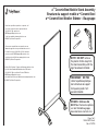
NOTE: DO NOT remove
the plastic shrink wrap from
the stand assembly until the
legs have been installed.
a3TM CeramicSteel Mobile Stand Assembly
Structure du support mobile a3TM CeramicSteel
a3TM CeramicSteel Mobiler Ständer – Baugruppe
HEX DRIVE
REMARQUE : NE PAS
retirer la pellicule plastique
de la structure du support
tant que les pieds n’ont
pas été installés.
HINWEIS: Entfernen Sie
NICHT die Plastikschrumpffolie
von der Ständerbaugruppe,
bevor die Beine montiert sind.
Si vous avez un problème, une question ou une
demande, appelez votre représentant du service à
la clientèle local au +32 89 32 32 31 30, envoyez-
nous un e-mail à EMEAsuppor[email protected]
ou visitez notre site Web sur www.polyvision.com
© 2019 PolyVision Corporation
Sollten Sie Probleme, Fragen oder Anfragen haben, rufen
Sie bitte Ihren Kundendienstmitarbeiter vor Ort unter
+32 89 32 31 30 an, schicken Sie eine E-Mail an
oder besuchen Sie unsere Website unter www.polyvision.com
© 2019 PolyVision Corporation

Page 2 of 2
1364416001 Rev A
Doc # 137780
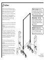
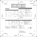
1. Remove the pan head Phillips screw from the
bottom of one of the vertical extrusions and discard.
Note: Remove and assemble each foot completely
before removing the screw on the other side.
2. Mount a leg to each side of the stand assembly
sing the hex drive 1-1/2" long screw provided.
Screws must be tightened to a minimum of 15 ft-lbs
of torque and a maximum of 20 ft-lbs of torque.
Notice the orientation of the half moon shaped
emboss on the top of the leg.
NOTE: DO NOT remove
the plastic shrink wrap from
the stand assembly until the
legs have been installed.
1
2
REMARQUE : NE PAS
retirer la pellicule plastique
de la structure du support
tant que les pieds n’ont pas
été installés.
HINWEIS: Entfernen Sie
NICHT die Plastikschrumpffolie
von der Ständerbaugruppe,
bevor die Beine montiert sind.
1. Retirez la vis cruciforme à tête cylindrique Phillips
du bas de l’un des profilés verticaux et débarrassez-
vous-en.
Remarque : Retirez et assemblez complètement
chaque base avant de retirer la vis située de l’autre
côté.
2. Sur chaque côté du support, installez un pied
en utilisant la vis hexagonale de 38,1 mm (1-1/2 po)
de long fournie. Les vis doivent être serrées à un
couple minimum de 20,3 N m (15 lb-pi) et un couple
maximum de 27,1 N m (20 lb-pi). Faites attention à
l’orientation représentée par le relief en forme de
demi-lune sur le dessus du pied.
1. Entfernen Sie die Zylinderschraube von der
Unterseite eines der Vertikalprofile und entsorgen
Sie diese.
Hinweis: Entnehmen und montieren Sie jeden Fuß
vollständig, bevor Sie auch die Schraube auf der
anderen Seite entfernen.
2. Bringen Sie unter Verwendung der mitgelieferten
1-1/2" Innensechskantschraube auf jeder Seite
der Ständerbaugruppe ein Bein an. Die Schrauben
sind auf ein Drehmoment zwischen 20 und 27 Nm
festzuziehen. Beachten Sie die Ausrichtung der
halbmondförmigen Prägung an der oberen Seite
des Beins.
-
 1
1
-
 2
2


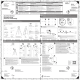
PolyVision Mobile Installationsanleitung
- Typ
- Installationsanleitung
- Dieses Handbuch eignet sich auch für
in anderen Sprachen
- français: PolyVision Mobile Guide d'installation
Verwandte Artikel
-
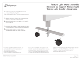 PolyVision Textura Light Installationsanleitung
-
PolyVision FLOW Installationsanleitung
-
 PolyVision Boundri Soft Installationsanleitung
-
 PolyVision Motif Soft Installationsanleitung
-
 PolyVision Motif Soft Installationsanleitung
-
 PolyVision Serif Installationsanleitung
-
 PolyVision Frameless Flow Installationsanleitung


