
Outline
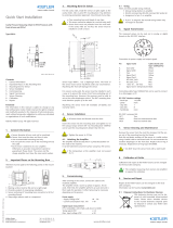
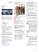
3. Mounting bore for sensor
For even cavity wall, mount the sensor at right angles to the
cavity. In hardened tool steel erode, mill or grind the H7-bore.
Note the centering and the alignment. Clean the threads free
of chips.
• Clean the mounting bore and the threads free of chips
• This sensor cannot be adapted to the contour!
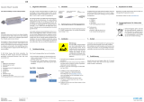
Quick Start Installation
Cavity pressure sensor for low viscosity resins with ø4 mm
Front
Type 6165A… (4 pC/bar, 200 bar, 200 °C)
1. General information
• Sensor diameter ø4 mm should not be machined
• The sensor front must be clean and without any
notches
• Use only the mounting socket recommended
• Do not pull on the cable to extract the sensor from
the bore
6165A_002-796e-03.18
Contents
1. General information
2. Critical points of the mounting bore
3. Mounting bore for sensor
4. Cable channeling and connector
5. Mounting the sensor
6. Installing cable connector
7. Mounting the nameplate
8. Functional test
9. Service and repairs
Foreword
Information in this document is subject to change without notice.
Kistler reserves the right to change or improve its products and
make changes in the content without obligation to notify any
person or organization of such changes or improvements.
© 2017 ... 2018 Kistler Group. All rights reserved. Kistler
Group products are protected by various intellectual property
rights. For more details visit www.kistler.com.
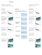
1. The bearing surface is flat and at right angles
2. The bevel protects the O-ring during mounting
3. Sensor centering in H7-bore is concentric to the mounting
thread M6
4. Sharp edge reduces the mark on the component
The Type 6165A... sensor has a diaphragm front. The front of
this sensor should not be machined under any circumstances.
Machining the front will damage the sensor.
Machining the sensor front shall invalidate all liability and
warranty claims!
• Sensorfront must not be machined
2. Critical points of the mounting bore
The following points in the bore must be watched:
A
3
2
4
1
0,01 A
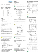
Type 1645C__
Kabel *
5
13
KIAG M4 pos.
2
O-Ring *
Type 1100A63
Kabel / cable
SW5,5
Type 1645C_
Sensor Typ 6165AA__
Massbild / Dimension drawing
O-Ring
Type 1100A57
6
4 g6
M5
2
13
L=...m
0
4-
5
0,012
0,004
-
-
M6
6,2
16,25
14,2
0,05
4,9 g7 -
-0,004
0,016
Sensor Typ 6165AAE / 6165AAG
Massbild / Dimension drawing
Kabel / cable
Type 1666A_
5
M5
0,97
L=1,5 m
* optionales Zubehör
Einbaubohrung
Mounting bore
M6
4,7
0,012
0
min.
5,5
7,5
4±0,02
0,2
4 H7 +
5,1 ±0,03
60°
Massbild / Dimension drawing
Sensor Typ 6165AA
200 °C
19,7
KIAG M4 neg.
öffentlich
Bik siehe Tabelle
Cadenas, 6165A_
a
100014613
Beo
26.01.2017
25.08.2016
100.262.345
26.01.2017
1 / 1
ges.
WZ-Dr-Sensor D4
Bl.
3:2
measure. analyze. innovate.
Erstmals verwendet
Erste Proj.-Nr.
Werkstoff
Änderung Datum Massstab
Ersatz für Kopie Datum
gez.
gepr. Hs
26.01.2017
Cau
Material-Nr.
26.01.2017
Zeichnungs-Nr.
A4
KIWAG-SWX_A4h
Ver.
Das Urheberrecht an dieser Zeichnung, die dem Empfänger
persönlich anvertraut wird, verbleibt unserer Firma.
Ohne unsere schriftliche Genehmigung darf die Zeichnung
weder kopiert noch vervielfältigt, noch an Drittpersonen
mitgeteilt oder zugänglich gemacht werden.
6165A_ _
0,2 mit PFA-Kabel D2, Typ 1645C0,2, L=0,2 m
0,4 mit PFA-Kabel D2, Typ 1645C0,4, L=0,4 m
0,6 mit PFA-Kabel D2, Typ 1645C0,6, L=0,6 m
0,8 mit PFA-Kabel D2, Typ 1645C0,8, L=0,8 m
1,2 mit PFA-Kabel D2, Typ 1645C1,2, L=1,2 m
1,6 mit PFA-Kabel D2, Typ 1645C1,2, L=1,6 m
sp mit PFA-Kabel D2, Typ 1645Csp, L=… m
Emit Single-Wire Kabel L=1,5 m
(mit Stecker Typ 1839 im Lieferumfang)
Gmit Single-Wire Kabel L=1,5 m
(ohne Stecker Typ 1839 im Lieferumfang)
Abis 200°C
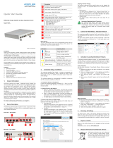
5. Mounting the sensor
• All sensor bores and threads must be clean
• Radial curves in the channels and at transitions
prevent damage to the cables
Insert the sensor in the thread of the mounting bore. Use
mounting tool Type 1700A177 to hand tighten it with a 3-5
Nm torque.
• Hand-tighten with a 3-5 N.m torque
• Use the Type 1300A177 mounting tool
6. Installing cable and connector
• Check again that edges of cable duct and hole are
chamfered
• Use a metal plate to cover open ducts/slots
• Attach cap and place on connector
6.1 Single-wire technology
• Single-wire cable must be completely enclosed in
the mold
• Single-wire cable may not be routed with power
cables
• Ensure that all contact surfaces and threads are
clean and dry
Kistler Group
Eulachstrasse 22
8408 Winterthur, Schweiz
Tel. +41 52 224 11 11
Fax +41 52 224 14 14
info@kistler.com www.kistler.com
6165A_002-796e-03.18 © 2017 ... 2018 Kistler Group
4 H7
+
0,012
0
4
±0,02
5,5
4,7
0,2
60°
M6
5,1
±0,03
min.
7,5
min. 29,4
SW5,5
Einbaubeispiel 6165A_
A4
0
1 / 1
3:2
measure. analyze. innovate.
Erstmals verwendet
Erste Proj.-Nr.
Werkstoff
Änderung
Datum
Massstab
Ersatz für
Kopie Datum
100014613 20.01.2017
gez.
gepr.
ges.
20.01.2017
Beo
100.268.757
Zeichnungs-Nr.
Material-Nr.
KIWAG-SWX_A4h
Ver.
Bl.
interne und externe Fertigung
Das Urheberrecht an dieser Zeichnung, die dem Empfänger
persönlich anvertraut wird, verbleibt unserer Firma.
Ohne unsere schriftliche Genehmigung darf die Zeichnung
weder kopiert noch vervielfältigt, noch an Drittpersonen
mitgeteilt oder zugänglich gemacht werden.
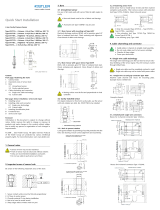
4. Cable channeling and connector
• Fixed cable reduces mounting
• Do not run cables next to hot runner cartridge
• Chamfer all sharp edges
• Cover open channels/slots
4.1 Cable technology
The single-wire technology uses the tool steel to ensure elec-
trical shielding of the sensor signal. Thus the wiring is routed
through drilled holes or channels.
• Single-wire cable must be completely enclosed in mold
• Single-wire cable must not be routed with power
cables
4.1.1 Single channel connector: single-wire Type 1839
Machine cable channel and recess for mounting plate.
Example shown: Drilled hole.
4.1.2 Multi channel connectors: single-wire or coaxial
Recess for 4-channel connector Type 1722A…
• Observe radii
• Cover open channels to prevent cable damage
Example shown: channel
Recess for 8-channel connector Type 1722A…
Outline
4.1.3 Single channel connector: coaxial
Machine cable channel and recess for mounting plate.
• Cover open channel to prevent cable damage

Kistler Group
Eulachstrasse 22
8408 Winterthur, Schweiz
Tel. +41 52 224 11 11
Fax +41 52 224 14 14
info@kistler.com www.kistler.com
6165A_002-796e-03.18 © 2017 ... 2018 Kistler Group
7. Mounting the nameplate
Rivet the nameplate to the side of the tool or mount it using
four M2.5 screws.
8. Functional test
Once the tool is assembled completely, check the insulation
of the sensor in the assembled state.
• Make sure all connectors are dry
• Use Type 1003 cleaning spray
8.1 Insulation check
Check the insulation of the sensor using the Type 5495
insulation tester. Insulation resistance >1013 Ω.
8.2 Check the function of the sensor
Test the sensitivity of the installed sensor using Test Set Type
5495.
Approx. measured value: 4 pC
• Use adaptor type 55124493 for testing, as the
diaphrame can be destroyed without it.
9. Service and repairs
Piezoelectric pressure sensors are maintenance-free. Insulati-
on and sensitivity of the installed sensor should, however, be
checked after each mold maintenace.
• Ensure that connector is dry
• Cover sensor hole during cleaning
• Use cleaning spray Type 1003
9.1 Insulation test
See chapter 8.1
9.2 Sensor functional check
See chapter 8.2
9.3 Removing sensor
Untighten sensor with mounting tool Type 1300B12Q01
and remove it from the mounting bore.
• Do not use a hammer on the sensor front
• Do not use a sharp center punch
9.4 Dismounting of cables
Fix Sensor with fork wrench AF5.5 and detach cable with
fork wrench AF 4 / AF 5 Type 5.210.164.
9.5 Single-wire repair
Slightly damaged cables can be repaired using the Repair Kit
Type 1207. If single-wire cables have been severed, solder
ends, slide over Teflon tube and cover with shrink tubing.
• Do not overheat sensor and cable when using
hot air blower
9.6 Repairs at Kistler
Factory repairs at Kistler are arranged by the local sales office
Information: www.kistler.com
9.7 Disposal instructions for electrical and electronic
equipment
Do not discard old electronic instruments
in municipal trash. For disposal at end of
life, please return this product to an autho-
rized local electronic waste disposal service
or contact the nearest Kistler Instrument
sales office for return instructions.
6.1.1 Cut & grip connection
Cut the single-wire cable to length and do not strip the insu-
lation. Open connector by hand, insert the single-wire cable
and close it again.
6.1.2 Installing single-wire connector
Install connector and mounting plate in recess. Attach cap
using one of the screws. Place cap on open connector.
Installation of connector Type 1839 and mounting plate
Installation of multichannel connector
Example: Type 1722A4...
6.2 Coaxial cable
6.2.1 Installation of coaxial connector
Install connector and mounting plate in recess. Attach cap
using one of the screws. Place cap on open connector.
-
 1
1
-
 2
2


in anderen Sprachen
- English: Kistler 6165AA Quick start guide
Verwandte Artikel
-
 Kistler 4001A202FA2,0 Schnellstartanleitung
-
 Kistler 6178C Schnellstartanleitung
-
 Kistler 5166A Schnellstartanleitung
-
 Kistler 6177B Schnellstartanleitung
-
 Kistler 5189A Schnellstartanleitung
-
 Kistler 1710B1 Bedienungsanleitung
-
 Kistler 1207 Schnellstartanleitung
-
 Kistler 5514A21D1 Schnellstartanleitung
-
 Kistler 4049B Bedienungsanleitung
-
 Kistler 4624AK Bedienungsanleitung


