Seite wird geladen ...

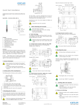
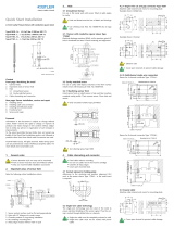
3. Mounting Bore for Sensor
For flat cavity walls, install the sensor at right angles to the
cavity. Erode, mill, or grind H7 mounting bore. Pay attention
to centering and position alignment. Clear thread of any chips.
• Clear mounting bore and thread of any chips
• This sensor cannot be adapted to a curved cavity wall!
• Sensor front must not protrude from the mold wall.
If the cavity walls are not flat, the sensor must be
installed in a with a recess
Quick Start Installation
Cavity Pressure Measuring Chain for RTM Processes with
Front ø9 mm and M12x1
Type 4001A
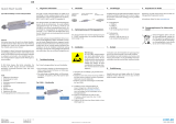
1. General Information
• Sensor diameter ø9 mm must not be machined
• Sensor front must be clean and free of nicks
• Use recommended mounting tool only
• Do not pull the sensor out of the mounting bore by
the cable
• Each sensor is tailored to its own amplifier.
Otherwise an accurate measurement cannot be
guaranteed. Please check: The sensor and the
charge amplifier must have the same serial number.
4001A_002-782e-06.16
Contents
1. General Information
2. Important Places on the Mounting Bore
3. Mounting Bore for Sensor
4. Sensor Installation
5. Commissioning
6. Signal Transmission
7. Sensor Cleaning
8. Calibration
9. Repairs
Foreword
The information in this manual is subject to change at any
time without prior notice. Kistler reserves the right to improve
and modify this product in the interests of technical advance-
ment without being under obligation to notify any individuals
or organizations of such
modifications.
©2016, Kistler Group. All rights reserved.
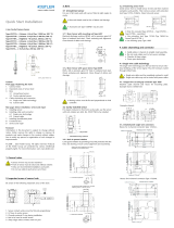
1. Bearing surface must be flat and at a right angle
2. Chamfer protects O-ring during installation
3. Sensor centering H7 mounting bore concentric to M12x1
mounting thread
4. Sharp edge reduces mark on component
Sensor Type 4001A... has a diaphragm front. The front of
this sensor must not be machined under any circumstances.
Machining the front will damage the sensor.
For uneven cavity walls, the sensor must be installed in such
a way as to prevent the sensor front from protruding out of
the mounting bore. However, the pressure must be able to
act on the entire diaphragm surface. The 9H7 mounting bore
must therefore project up to the wall.
Machining the sensor front will invalidate all liability and
warranty claims.
2. Important Places on the Mounting Bore
Attention must be paid to the following points on the mount-
ing bore:
A
3
2
4
1
0,01 A
A
3
2
4
1
0,01 A
12
R
min.35
Min. 90 (bei abgedeckten Einbau)
6 *
0
min.
20
0,015
0
+
9 H7
+0
0,2
13
M12x1
20
11 H7 +0,018
0,4x30°
öffentlich
Material-Nr.
Ver.
Zusammenstellung Einbau 4001A
100.251.696
gepr.
ges.
KIWAG-SWX_A4h
01 / 1
1:3
measure. analyze. innovate.
Erstmals verwendet
Erste Proj.-Nr.
Werkstoff
Änderung Datum Massstab
Ersatz für Kopie Datum
18030846 4001A
A4 Bl.
19.01.2016 Beo
gez.
Zeichnungs-Nr.
Das Urheberrecht an dieser Zeichnung, die dem Empfänger
persönlich anvertraut wird, verbleibt unserer Firma.
Ohne unsere schriftliche Genehmigung darf die Zeichnung
weder kopiert noch vervielfältigt, noch an Drittpersonen
mitgeteilt oder zugänglich gemacht werden.
4. Sensor Installation
• All sensor bores and threads must be clean
Insert the sensor into the mounting bore and tighten to 10
Nm using a torque wrench (AF 12). Mounting tool 1300A42
can be used for mounting bores deeper than 30 mm.
• Tighten the sensor to 10 Nm
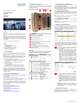
4.1. Attaching the Amplifier
The amplifier should be attached in a protected position on
the mold or the machine.
It can be fastened to any level surface using four M4 screws.
• The temperature at the amplifier must not exceed
75°C.
7. Sensor Cleaning and Maintenance
Remove the sensor from the mold for cleaning. Pull the sen-
sor out of the mounting bore by the thread.
Rub dirt and plastic residues off the sensor in a radial motion
using a leather cloth or soft brass brush. Do not overstrain the
sensitive diaphragm on the front face. Replace the O-ring if
necessary. Replacement O-ring Type 55139386.
• Do NOT clean the sensor front with a steel brush!
5. Commissioning
After screwing in the sensor, connect the cable to the
matched amplifier.
The amplifier needs a warm-up phase of approx. 30 sec-
onds. After that, the amplifier performs an auto tare and is
then ready for operation. Further taring may be necessary
depending on the process.
Power supply
- Supply voltage VDC 18 ... 30
- Current consumption max. mA < 40
Digital input measurement
(TTL compatible, active high, pull-down to GND)
Taring signal VDC > 3.2
Max. input voltage VDC ± 30
8. Calibration at Kistler
Calibration and repairs at the Kistler factory can be arranged
via the local sales company.
• The complete measuring chain (sensor and amplifier)
is required for calibration
Kistler Group
Eulachstrasse 22
8408 Winterthur, Switzerland
Tel. +41 52 224 11 11
Fax +41 52 224 14 14
info@kistler.com www.kistler.com
6. Signal Transmission
The measured values can be read out in analog or digital
format via the RS-232C interface.
9. Service and Repair
Repairs at the Kistler factory can be arranged via the local
sales company.
Information can be found at www.kistler.com
9.1 Disposal Instructions for Electronic Devices
Old electronics devices may not be dis-
posed of with household refuse/residual
waste. Please return obsolete devices
to the nearest electronics disposal point
for disposal or contact your Kistler sales
representative.
4001A_002-782e-06.16 ©2016, Kistler Group
Das Urheberrecht an dieser Zeichnung, die dem Empfänger per-
sönlich anvertraut wird, verbleibt unserer Firma. Ohne unsere
schriftliche Genehmigung darf die Zeichnung weder kopiert noch
vervielfältigt, noch an Drittpersonen mitgeteilt oder zugänglich ge-
macht werden.
öffentlich
Änderung
100010632-T1
Datum
26.01.2016
Erzeugersystem
Word 2010
Europäische
Projektion
Erste Proj.-Nr.
Kopie Datum
Niederdruck-Messkette
Spezifikations - Kontrollblatt
gez.
22.01.2016
Beo
kISTLER
Format
A4
Dokumentnummer
Version
n
Blatt 1
gepr.
25.01.2016
Cau
4001A___-01
b
Kistler Instrumente AG, Winterthur
Switzerland
von 5
ges.
25.01.2016
Hs
Kurzbeschreibung
Die piezoresistive 3-Kanal Niederdruck- Messkette mit integriertem Brückenverstärker eignet sich
besonders zur Messung vom statischen Werkzeuginnendruck beim Spritzgiessen von niederviskosen
Kunststoffen bis 250°C. Typische Anwendung ist die Forminnendruckmessung beim RTM Prozess.
Hauptmerkmal
Statisch messend von -1…50 bar, Temperaturkompensiert
Hoher Temperaturbereich bis 250°C mit Temperaturausgang 10mV/K
Einfache Montage und IP 65 für den industriellen Einsatz
Zwei frei programierbare, unabhängige Messbereiche
Autokalibration auf Maschine über RS232 Befehl
Manueller Tariertaster
Das Gerät ist im Sinne der EG Richtlinie 2004/108/EG conform und erfüllt die EMV Normen:
EN 61000-6-4 und EN 61000-6-2 Störfestigkeit Produktenorm: EN61326-1 (Klasse A)
4001A___-01 - b - YS0 - SKB - öffentlich - Freigegeben --- siehe Tabelle --- 20-Jun-2016 05:48 (CET) - mtz@ch.int.kistler.com
Connection to power supply and output signals
Pin Signal name Cable strand color
Type 1200A227A2
A Exct GND White
B Signal GND Brown
C Tara Green
D Signal Out 1 Yellow
E Signal Out 2 Gray
F RS-232C_RxD Pink
G RS-232C_TxD Blue
H +Exct 18 … 30 VDC Red
J Signal Out 3 (temperature) Black
Connecting cable Type 1200A227A2 can be used to connect
to a data logger or PC.
RS-232C interface settings
- baud bps 115,200
- parity none
- stop bits 1
- data bits 8
- handshake none
RS-232C command list:
:SCT Tare
:RMD Read out measurement data
:RCD Read out control data
5.1 Taring
There are three possible taring methods.
• Manual taring button on amplifier
• RS-232 command (see RS-232 command list, Section 6)
• Assignment of pin C on amplifier
• If pin C is assigned, the manual taring button may
no longer be actuated
1/1