Seite wird geladen ...

Betriebsanleitung
Operating instruction
POMUX
®
KH53
Absoluter Linear-Encoder: Typen 38 m, 107 m, 354 m
und 1 700 m
Absolute Linear Encoder: Types 38 m, 107 m, 354 m
and 1 700 m
POMUX
®
KH53 Advanced
Absoluter Linear-Encoder: Typen 54 m und 548 m
Absolute Linear Encoder: Types 54 m and 548 m

© by SICK STEGMANN GmbH
Für diese Dokumentation beansprucht die SICK STEGMANN GmbH
Urheberrechtsschutz.
Diese Dokumentation darf ohne vorherige schriftliche Zustimmung der
SICK STEGMANN GmbH weder abgeändert, erweitert, vervielfältigt
oder an Dritte weitergegeben werden.
Mit den Angaben in dieser Dokumentation werden die Produkte spezifiziert,
keine Eigenschaften zugesichert.
Die weltweiten Patentrechte sind im Besitz der SICK STEGMANN GmbH.
SICK STEGMANN GmbH
Dürrheimer Straße 36
D-78166 Donaueschingen
Telefon: 07 71/8 07 - 0
Telefax: 07 71/8 07 - 1 00
Internet: www.sick.com
e-mail: info@sick.de
Ausgabedatum: 06/2019
Design- und Geräteänderungen vorbehalten.
© by SICK STEGMANN GmbH
SICK STEGMANN GmbH claims copyright over this documentation.
This documentation may neither be altered, expanded, reproduced
or passed to third parties without the previous written agreement of
SICK STEGMANN GmbH.
The products are specified by the statements in this documentation;
no assurance of the properties is given.
The world-wide patent rights are the property of SICK STEGMANN GmbH.
SICK STEGMANN GmbH
Dürrheimer Straße 36
D-78166 Donaueschingen
Telephone: +49 7 71/8 07 - 0
Fax: +49 7 71/8 07 - 1 00
Internet: www.sick-stegmann.com
e-mail: info@sick.de
Issue date: 06/2019
The right is reserved to change designs and devices

Dokumentationsübersicht / Documentation overview
8013442/13MT/2019-06-26 SICK • Subject to change without notice 1
Dokumentationsübersicht
Die Gesamtdokumentation über den POMUX
®
KH53 / POMUX
®
KH53 Advanced umfasst
folgendes:
z
z
Produktinformation
z
PROFIBUS Inbetriebnahme Anleitung
(für Geräte mit Profibus-Schnittstelle)
z
Betriebsanleitung *
*
dies ist die vorliegende Dokumentation.
Documentation overview
The overall documentation on the POMUX
®
KH53 / POMUX
®
KH53 Advanced comprises
the following:
z
Product information
z
Profibus Commissioning Instructions
(for devices with Profibus interface)
z
Operating instruction*
*
this is the present documentation.

Inhaltsverzeichnis
2 SICK • Subject to change without notice 8013442/13MT/2019-06-26
Inhaltsverzeichnis
Kapitel Thema Seite
1 Vorwort 5
2 Allgemeine Hinweise 7
2.1 Gültigkeit 7
2.2 Symbole und ihre Bedeutung 7
3 Sicherheitshinweise 8
3.1 Personenschutz 8
3.1.1 Sicherheitshinweise für die Montage / Reparatur 8
3.2 Gerätesicherheit 9
4 Prüfung der Systemkomponenten 11
4.1 Eingangskontrolle 11
4.2 Lieferumfang 12
4.3 Reklamationen 12
4.4 Nachbestellung von Maßverkörperungselementen 12
5 Umgebungsbedingungen 13
6 Montagehinweise 15
6.1 Montagevarianten 16
6.2 Montagetoleranzen 20
6.2.1 Montagetoleranzen des POMUX
®
KH53 20
6.2.2 Montagetoleranzen des POMUX
®
KH53 Advanced 21
6.3 Montageanordnung 22
6.4 Maße- und Berechnungstabelle 23
6.4.1 Maße- und Berechnungstabelle für den POMUX
®
KH53 Advanced 23
6.4.2 Maße- und Berechnungstabelle für den POMUX
®
KH53 24
7 Montage / Demontage / Erweiterung 25
7.1 Montage des Lesekopfs – Beispiel 25
7.2 Montage der Maßverkörperungselemente 29
7.2.1 Montage mit Befestigungswinkel – Beispiel 30
7.2.2 Montage mit Klemmhalter – Beispiel 33
7.3 PIN- und Aderbelegung der SSI-Schnittstelle 38
7.4 Profibus-Anschluss 39
7.5 Demontage des POMUX
®
KH53-Längenmesssystems 42
7.6 Erweiterung 43
8 Inbetriebnahme / Testlauf 44
9 Störungen / Reparatur 45
9.1 Störungsursachen 45
9.2 Reparatur 46
10 Wartung / Reinigung 47
10.1 Wartung 47
10.2 Reinigung 47

List of contents
8013442/13MT/2019-06-26 SICK • Subject to change without notice 3
List of contents
Chapter Title Page
1 Foreword 1
2 General advice 3
2.1 Validity 3
2.2 Symbols and their meaning 3
3 Safety advice 4
3.1 Personal protection 4
3.1.1 Safety advice for installation / repair 4
3.2 Device safety 5
4 Checking the system components 7
4.1 Inward monitoring 7
4.2 Scope of supply 8
4.3 Complaints 8
4.4 Re-ordering measuring elements 8
5 Ambient conditions 9
6 Installation advice 11
6.1 Installation variants 12
6.2 Installation tolerances 16
6.2.1 Assembly tolerances of the POMUX
®
KH53 16
6.2.2 Assembly tolerances of the POMUX
®
KH53 Advanced 17
6.3 Installation arrangements 18
6.4 Dimension and calculation table 19
6.4.1 Dimension and calculation table for POMUX
®
KH53 Advanced 19
6.4.2 Dimension and calculation table for POMUX
®
KH53 20
7 Mounting / Disassembly / Expansion 21
7.1 Mounting of the read head – Example 21
7.2 Mounting of the measuring elements 25
7.2.1 Direct mounting with fastening clamps – Example 26
7.2.2 Mounting with spacer supports – Example 29
7.3 PIN- and wire allocation of the SSI-interface 34
7.4 Profibus connection 35
7.5 Disassembly of the POMUX
®
KH53 length measuring system 38
7.6 Expansion 39
8 Commissioning / Test Run 40
9 Faults / Repair 41
9.1 Fault causes 41
9.2 Repair 42
10 Maintenace / Cleaning 43
10.1 Maintenance 43
10.2 Cleaning 43

Vorwort / Foreword
4 SICK • Subject to change without notice 8013442/13MT/2019-06-26

Vorwort / Foreword
8013442/13MT/2019-06-26 SICK • Subject to change without notice 5
1
Vorwort
1 Lesekopf
2 Maßverkörperungselement (ME)
Abb. 1-1 POMUX
®
KH53-Längenmesssystem
Sehr geehrter Kunde,
sehr geehrter Monteur
,
Sie stehen vor der Aufgabe ein POMUX
®
KH53-Längenmesssystem zu montieren.
Diese Betriebsanleitung soll Ihnen das erfor-
derliche Wissen vermitteln, damit Sie die Mon-
tage schnell und richtig durchführen können.
Bitte lesen Sie diese Anleitung aufmerk-
sam durch und beachten Sie besonders
die Hinweise und Warnvermerke!
1 Foreword
1 Read head
2 Measuring element (ME)
Fig. 1
-1 POMUX
®
KH53 length measuring sys
tem
Dear c
ustomer,
dear installer,
You are about to undertake the task of mount-
ing a
POMUX
®
KH53 length measuring
sy
stem.
These
installation
instructions are intended to
give you the knowledge which is necessary
for you to be able to carry out the mounting
quickly and correctly.
Please read these instructions carefully
and pay particular attention to the advice
and warning notes!

Vorwort / Foreword
6 SICK • Subject to change without notice 8013442/13MT/2019-06-26
Der POMUX
®
KH53 (Positionsmultiplexer) ist
ein berührungsloses, absolutes Längenmess-
system.
Das System ist für die Längenmessung bis zu
max. 1,7 Kilometer geeignet, und dies sowohl
im Innenbereich, als auch unter rauen Umge-
bungsbedingungen im Außenbereich.
Das System besteht aus mindestens 2 Teilen:
– dem Lesekopf
– den Maßverkörperungselement(en)
Maßverkörperungselement
Ein Maßverkörperungselement besteht aus
einem runden Aluminiumprofil, in dem in ge-
nau definierten Abständen Dauermagnete be-
festigt sind. Der Abstand der Magnete zuei-
nander stellt die Codierung dar.
Die erforderlichen Abstände von Maßverkör-
perungselement zu Maßverkörperungsele-
ment werden durch den Einsatz einer Lehre
bei der Montage erreicht.
Lesekopf
Der Lesekopf beinhaltet die Auswerteelektro-
nik und eine Reihe magnetfeldempfindlicher
Sensoren. Beide Teile sind in einem recht-
eckigen Aluminiumprofil untergebracht.
Der Lesekopf wird im Anwendungsfall entlang
der Maßverkörperungselemente geführt.
Die magnetfeldempfindlichen Einzelsensoren
registrieren die Felder der Dauermagnete
und die Auswerteelektronik ermittelt daraus
einen definierten absoluten Positionswert.
Über eine Leitung werden die absoluten Posi-
tionsdaten des Lesekopfs zu einer Steuerung
bzw. zu einem Host-Rechner übertragen.
Daten-Schnittstelle
Das System kann entweder mit einer
– SSI- oder einer
– Profibus-Schnittstelle
ausgestattet sein.
Bei Fragen bezüglich des POMUX
®
KH53
stehen wir Ihnen gerne zur Verfügung.
Die Telefon-Nummer finden Sie auf der ersten
Innenseite dieser
Betriebsanleitung.
Ihre
SICK STEGMANN GmbH
The POMUX
®
KH53 (position multiplexer) is
a non
-contact, absolute length measuring
sy
stem.
The system is suitable for length measuring
up to a maximum of 1.7 kilometres and this is
possible indoors as well as outdoors under
aggressive am
bient conditions.
The system consists of at least two parts:
–
the read head
– the measuring element(s)
M
easuring element
The measuring element consists of a round
aluminium
profile in which permanent mag-
nets
are located at accurately defined inter-
vals. The spacing of the
magnets from one
another represents the codi
ng.
The necessary spacing between subsequent
measuring elements is controlled using the
mounting gauge during
installation.
Read he
ad
The read head includes the evaluation elec-
tronics and a series of individual
sensors
which are sensitive to magnetic fields.
Both parts are accommodated in a rectangu-
lar aluminium
profile. In use, the sensor is
guided alongside the measuring elements.
The individual
sensors, which are sensitive to
magnetic fields, register the fields of the per-
manent magnets
and the evaluation electron-
ics determine from these a defined absolute
position
value.
The absolute position data of the read head is
transmitted via a cable to a control unit or to a
host computer.
Data interfa
ce
The system can be equipped with the follow-
ing interf
aces
– SSI or a
– Profibus interface.
If there are any questions in relation to the
POMUX
®
KH53 system, we shall be pleased
to a
nswer them.
The telephone number will be found on the in-
side front cover of these
installation instructions.
Yours sincerely,
SICK STEGMANN GmbH

Allgemeine Hinweise / General advice
8013442/13MT/2019-06-26 SICK • Subject to change without notice 7
2 Allgemeine Hinweise
2.1 Gült
igkeit
Diese Betriebsanleitung ist sowohl für das be-
rührungslose, absolute Längenmesssystem
– POMUX
®
KH53 als auch für das System
– POMUX
®
KH53 Advanced gültig.
Die beiden Messsysteme unterscheiden sich
in folgenden technischen Daten:
– Montage-Toleranzen
– Messbereiche
– Betriebsumgebungs-Temperaturbereich
– Identifikationsbuchstaben der Maßverkör-
perungen
Die nachfolgenden Beschreibungen sind ge-
nerell für beide Systeme gültig. Die Beschrei-
bungen der oben genannten unterschiedli-
chen technischen Daten sind systemspezi-
fisch gekennzeichnet.
Die Konfiguration des Längenmesssystems ist
kundenspezifisch, d. h. das System setzt sich
aus einem Lesekopf und einer von der Mess-
länge abhängigen Anzahl Maßverkörperungs-
elementen zusammen.
2.2 Symbole und ihre Bedeutung
Texte, die mit diesem Symbol gekennzeichnet
sind, enthalten sehr wichtige Hinweise, unter
anderem auch zur Abwendung von gesund-
heitlichen Gefahren!
Beachten Sie diese Texte unbedingt!
Texte, die mit diesem Symbol gekennzeichnet
sind, enthalten sehr wichtige Hinweise, unter
anderem auch, um Sachbeschädigungen
vorzubeugen!
Beachten Sie diese Texte unbedingt!
Dieses Symbol weist auf Texte hin, die Kom-
mentare / Hinweise oder Tipps enthalten.
Dieser Punkt kennzeichnet die Beschreibun-
gen von Tätigkeiten, die Sie ausführen sollen.
Dieser Strich kennzeichnet Aufzählungen.
2 General advice
2.1 Validity
These Assembly Instructions apply to both the
non
-contact, absolute length measuring system
–
POMUX
®
KH53 and to the
– POMUX
®
KH53 Advanced system.
T
he two measuring systems differ in the
following technical specifications:
– assembly tolerances
– measuring ranges
– temperature range of the operating
environment
– identification letters of the measuring
elements
The descriptions below generally apply to
both systems. The descriptions of the different
technical specifications given above are iden-
tified in a system
-specific manner.
The configuration of the length measuring
system is specific to the customer, that is to
say the system is composed of a read head
and a number of measuring elements. The
number of measuring elements will depend
upon the measurement length.
2.2 Symbols and their meaning
Paragraphs which are identified with this
symbol contain very important advice; this al-
so i
ncludes advice for averting health
and safety risks.
Observe these paragraphs without fail.
Paragra
phs which are identified with this
symbol contain very important advice; this al-
so i
ncludes how to avoid damage to
property.
Observe these paragraphs without fail.
Thi
s symbol indicates paragraphs which
contain comments / advice or tips.
T
his bullet identifies the description of actions
which you should carry out.
T
his dash identifies listings.
xx
–

Sicherheitshinweise / Safety advice
8 SICK • Subject to change without notice 8013442/13MT/2019-06-26
3 Sicherheitshinweise
3.1 Personenschutz
3.1.1 Sicherheitshinweise für die
Montage / Reparatur
Die Montage des Längenmesssystems erfor-
dert gute mechanische Kenntnisse und eine
präzise und sichere Arbeitsweise! Deshalb
sollte die Montage nur von einer ausgebilde-
ten Fachkraft durchgeführt werden!
x
x
Schalten Sie alle von der Montage bzw.
Reparatur betroffenen Geräte / Maschi-
nen / Anlagen ab!
Trennen Sie die Geräte / Maschinen /
Anlagen gegebenenfalls vom Netz!
x
Machen Sie pneumatische / hydrauli-
sche Geräte / Maschinen / Anlagen vor
der Montage bzw. Reparatur drucklos!
x
Stellen Sie gegebenenfalls Warnschilder
auf, um die unbeabsichtigte Inbetrieb-
nahme der Geräte / Maschinen / Anlagen
zu verhindern.
x
Wir weisen Sie nachdrücklich darauf
hin, dass unser Längenmesssystem
– bei fehlerhaften Sicherheitseinrich-
tungen und / oder
– bei beschädigten Komponenten / Bau-
teilen (z. B. beschädigte Steckverbin-
dungen) nicht in Betrieb genommen
werden darf!
Trennen Sie in diesen Fällen das Sys-
tem vom Stromnetz!
x
Sorgen Sie dafür, dass während des
Defekts bzw. der Reparatur das System
nicht versehentlich an das Stromnetz
angeschlossen werden kann! Stellen
Sie gegebenenfalls Warnschilder auf!
x
Führen Sie die Montage- / Reparaturar-
beiten unter Einhaltung der berufsge-
nossenschaftlichen Sicherheits- und
Unfallverhütungsvorschriften durch.
x
Vermeiden Sie (gegebenenfalls durch
Abdeckungen oder ähnliches), dass
Hände oder Finger zwischen Lesekopf
und Maßverkörperungselemente gelan-
gen können!
x
Führen Sie nach Abschluss der Repara-
turarbeiten einen Testlauf des Systems
durch und prüfen Sie die korrekte Funk-
tionsweise der Sicherheitseinrichtun-
gen!
3 Safety advice
3.1 Personal protection
3.1.1 Safety advice for
installation / repair
The assembly of the length measuring system
requires good mechanical knowledge and
accurate and safe operation! Therefore,
assembly should only be performed by a
trained specialist!
x Before mounting, switch off all the
devices / machines / plant affected.
If appropriate, isolate the devices /
machines / plant from the mains.
x Before mounting, remove the pressure
from pneumatic / hydraulic devices /
machines / plant.
x If necessary, set up warning signs in
or
der to prevent the inadvertent starting
up of the devices / machines / plant.
x Our length measuring system must not
be commissioned
– if any safety equipment is faulty
and / or
–
if any components / subassemblies
are damaged (e. g. damaged con-
nectors).
In these cases, i
solate the system from
the voltage supply.
x Ensure that the system cannot inadvert-
ently be connected to the voltage supply
if there is a defect or the system is
under repair. If necessary, set up war
n-
ing signs.
x Observe the professional safety and
accident prevention regulations when
carrying out the installation / repair
work.
x Ensure it is not possible for hands or
fingers to get between read head and
measuring element(s),( if necessary by
using covers or the like).
x After concluding the repair work, carry
out a test run of the system and check
the correct functioning of the safety
equipment.

Sicherheitshinweise / Safety advice
8013442/13MT/2019-06-26 SICK • Subject to change without notice 9
3.2 Gerätesicherheit
– Das Gerät ist ein nach den anerkannten
Regeln der Technik hergestelltes Qualitäts-
produkt.
– Das Längenmesssystem hat das Herstel-
lerwerk in sicherheitstechnisch einwand-
freiem Zustand verlassen!
– Um diesen Zustand zu erhalten, müssen
Sie als Monteur Ihre Aufgabe entsprechend
den Beschreibungen in dieser Anleitung,
fachlich richtig und mit größter Präzision
durchführen.
– Wir setzen voraus, dass Sie über fundierte
Kenntnisse im Maschinenbau, der Fein-
mechanik und der Elektrik verfügen!
– Das System darf nur zu dem seiner Bauart
entsprechenden Zweck verwendet werden!
– Die im Datenblatt angegebene Schutzart
ist nur bei aufgesteckten Gegensteckern
gegeben.
x
x
Schalten Sie alle von der Montage be-
troffenen Geräte / Maschinen / Anlagen
ab! Trennen Sie die Geräte / Maschinen /
Anlagen gegebenenfalls vom Netz!
x
Machen Sie pneumatische / hydrauli-
sche Geräte / Maschinen / Anlagen vor
der Montage drucklos!
x
Stellen Sie gegebenenfalls Warnschilder
auf, um die unbeabsichtigte Inbetrieb-
nahme der Geräte / Maschinen / Anlagen
zu verhindern.
x
Sorgen Sie z. B. bei langen Montage-
strecken und im Freiland dafür, dass
keine Anlagenteile in den Montagebe-
reich eindringen!
x
Verlegen Sie die Datenleitung vom
Lesekopf zur Steuerung so, dass sie
– im Betrieb beim Abfahren der Mess-
strecke nicht hängen bleibt;
– nicht gequetscht, abgeknickt oder
anderweitig beschädigt wird;
– nicht direkt neben Energieleitungen
verläuft.
x Schalten Sie bei Elektro-Schweißarbei-
ten, die in unmittelbarer Nähe des Sys-
tems durchgeführt werden, dessen Ver-
sorgungsspannung aus, um eine Be-
schädigung des Systems durch hohe
Induktionsströme auszuschließen!
3.2 Device safety
– The Device is a quality product which is
produced in accordance with the recog-
nised industrial regulations.
– The length measuring system left the man-
ufacturer's works in a perfect, safe condi-
tion!
– In order to maintain this condition, as in-
staller you must carry out your task in
accordance with the descriptions in these
instructions, technically correctly and with
the greatest possible precision.
– We assume that you have fundamental
knowledge in mechanical engineering, pr
e-
cision mechanics and electrical engineer-
ing!
– The length measuring system must be used
only for purposes corresponding to its con-
struction!
– The enclosure rating stated in the data
sheet
only applies with mating connectors
fitted.
x Before mounting, switch off all the
relevant device / machines / plant!
x If appropriate, isolate the devices /
machines / plant from the mains!
x Before mounting, remove the pressure
from pneumatic / hydraulic devices /
machines / plant!
x If necessary, set up warning signs in
order to preve
nt the inadvertent starting
up of the devices / machines / plant.
x Make sure, for example in the case of
long measuring paths and outdoors,
that parts of the plant cannot enter the
mounting area!
x Lay the data cable from the read head to
the controller unit in such a way that
– it does not get caught up in operation
when travelling along the measuring
path;
– it is not crushed, kinked or otherwise
damaged;
– it does not run directly alongside
power lines.
x If electrical welding operations are be-
ing carried out directly in the vicinity of
the system, switch off their voltage
sup
ply in order to exclude damage to
the system as a result of high induction
currents.

Sicherheitshinweise / Safety advice
10 SICK • Subject to change without notice 8013442/13MT/2019-06-26
x
x
Öffnen Sie den Lesekopf oder die Maß-
verkörperungselemente nicht!
Das Öffnen des Lesekopfs oder der
Maßverkörperungselemente
– beeinträchtigt die Funktionssicherheit
und
– führt zur Erlöschung der Gewährleis-
tung!
x
Verwenden Sie für Montagearbeiten nur
unbeschädigte, fehlerfreie Werkzeuge /
Bauteile!
x
Setzen Sie das System nicht in Betrieb,
wenn irgendwelche Teile beschädigt
sind!
x
Führen Sie nach der Montage des Sys-
tems und vor Freigabe der davon be-
troffenen Geräte / Maschinen / Anlagen
für den Produktionsprozess einen Test-
lauf durch.
x Do not open the read head or the
measuring elements!
The opening of the read head or of
the measuring elements
– impairs the functional safety
and
– nullifies the warranty.
x Use only undamaged, fault free tools /
components for the mounting opera-
tions.
x Do not start up the system if any parts
are damaged.
x After mounting the system, and before
releasing the devices / machines / plant
used for the production process, carry
out a test run.

Umgebungsbedingungen / Ambient conditions
8013442/13MT/2019-06-26 SICK • Subject to change without notice 11
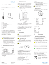
4
Prüfung der
Systemkomponenten
4.1 Eingangskontrolle
1 Lesekopf
2 Typenschild
3 Identifikations-Code bestehend aus
Identifikationsbuchstabe und -nummer
4 richtige Maßverkörperungselemente
5 falsches Maßverkörperungselement
Abb. 4-1
x
x
Prüfen Sie
– unmittelbar nach Anlieferung die Teile
des Längenmesssystems auf eventuelle
Transportschäden und Mängel.
– anhand des beiliegenden Lieferscheins
die Anzahl der Teile und die Vollständig-
keit der Kleinteile.
– ob alle Maßverkörperungselemente den
gleichen Identifikationsbuchstaben haben
wie auf dem Typenschild des Lesekopfs
angegeben und ob die Maßverkörperungs-
Elemente durchgehend von 1 bis n num-
meriert sind. Der Lesekopf und die Maß-
verkörperungselemente bilden ein Sys-
tem und müssen alle mit dem gleichen
Buchstaben gekennzeichnet sein!
x
Lassen Sie keine Teile in der Verpackung
zurück.
4 Checking the system
components
4.1
Inward monitoring
1 Read head
2 Type label
3 Identifier code consisting of identification
letter and identification number
4 correct measuring element(s)
5 wrong measuring element
Fig. 4
-1
x
Check
–
the parts of the measuring system for
any transport damage
and deficiencies
immediately upon receipt
– the accompanying delivery note to
ensure that the number of parts is
correct and the completeness of the
small parts.
–
whether all the measuring elements have
the same identification
letters as are
specified on the type label of the sen
sor,
and whether the measuring ele
ments are
numbered con
tinuously from 1 to n. The
sensor and the measuring elements
form one system and must all be identi-
fied with the same letters.
x
Do not leave any parts in the packag
ing.

Sicherheitshinweise / Safety advice
12 SICK • Subject to change without notice 8013442/13MT/2019-06-26
4.2 Lieferumfang
Ein komplettes POMUX
®
Längenmess-
system besteht aus:
– dem Lesekopf
– den Maßverkörperungselementen
– der Befestigungstechnik
– der Montagelehre
– der Anschlusstechnik
– der Dokumentation über die Anschlussbe-
legung der Lesekopfschnittstelle
Der Lieferumfang kann im einzelnen ab-
weichen, soweit kein Komplettsystem be-
stellt wurde!
4.3 Reklamationen
Schadensersatzansprüche, die sich auf
Transportschäden beziehen, können nur gel-
tend gemacht werden, wenn unverzüglich das
Zustell-Unternehmen benachrichtigt wird.
x
x
Fertigen Sie für Rücksendungen (wegen
Transportschäden / Reparaturen) umge-
hend ein Schadensprotokoll an und senden
Sie die Teile, wenn möglich in der Original-
verpackung, an das Lieferwerk zurück.
x
Legen Sie der Rücksendung folgende
Angaben bei:
– Name und Adresse des Empfängers
– Sach- / Bestell- / Teile-Nummer
– Beschreibung des Defekts
4.4 Nachbestellung von Maßver-
körperungselementen
Jedem Maßverkörperungselement ist ein
Identifikations-Code eingeprägt.
Wurde eines oder mehrere dieser Maßverkör-
perungselemente beschädigt oder zerstört,
geben Sie bei Nachbestellungen jeweils den
betreffenden Identifikations-Code an.
4.2 Scope of supply
A complete POMUX
®
length measuring
sy
stem consists of:
– read head
– measuring elements
– mounting systems
– mounting gauge
– connection systems
– documentation relating to the pin / wire
allocation of the sensor interface
The individual scope of supply might be
different if a complete system was not
o
rdered!
4.3 Complaints
Claims for replacement of damaged goods
which relate to
transport damage can only be
considered valid if the delivery company is
n
otified without delay.
x For returns (because of transport damage /
repair), prepare a damage report immedi-
ately and send the parts back to the manu-
facturing plant, if possible in the original
packaging.
x Attach the following information to the
return:
– name and address of the receiver
– reference / order / part numbers
– description of the defect
4.4 Re-ordering measuring
elements
An identification number is stamped onto each
measuring element.
If one or more of these measuring elements
has been damaged or destroyed, specify the
relevant
identification numbers when re-
ordering.

Umgebungsbedingungen / Ambient conditions
8013442/13MT/2019-06-26 SICK • Subject to change without notice 13
5 Umgebungsbedingungen
Das POMUX
®
Längenmesssystem ist für
raue Betriebsbedingungen konzipiert!
Dennoch sind für seine Montage und den
späteren Betrieb Einschränkungen zu beach-
ten!
x
x
Achten Sie darauf, dass
– das System entsprechend den nachfol-
gend aufgeführten Montagehinweisen
montiert wird.
– das System oder einzelne Teile des Sys-
tems entsprechend den in den techni-
schen Daten spezifizierten Kennwerten
eingesetzt werden (siehe Datenblatt
POMUX
®
KH53).
Die Nichtbeachtung der Montagehinwei-
se bzw. der Einsatz außerhalb der spezi-
fizierten Kennwerte kann die Genauigkeit
bzw. die Funktion des Systems negativ
beeinflussen.
Der Einsatz des Systems unter Einwirkung
von radioaktiver Strahlung darf nur nach
Absprache mit dem Hersteller erfolgen!
Leistungsstarke elektrische Verbraucher
und Permanentmagnete erzeugen Magnet-
felder, die die Funktion des Systems nega-
tiv beeinflussen können! Deshalb muss
zwischen dem Lesekopf (bzw. dessen Ver-
fahrweg über die gesamte Messstrecke)
und dem Verbraucher und dessen Strom-
versorgungsleitungen bzw. dem Perma-
nentmagnet ein ausreichender Abstand
eingehalten werden!
x
Vermeiden Sie im Umkreis von 80 mm
um die Maßverkörperungselemente
und den Lesekopf ferromagnetisches
Material!
5 Ambient conditions
The POMUX
®
length measuring system is
designed conceived for aggressive operating
conditions.
However, some restrictions are to be observed
for its mounting and subsequent o
peration.
x Take care that
– the system is mounted in accordance
with the installation advice listed below.
– the system or individual parts of the
system are employed in accordance with
the characteristic values specified in the
technical data (see data sheet POMUX
®
KH53).
The non-observance of the installation
ad vice or use outside the specified char-
acteristic values can have a negative
influence on the accuracy of the system.
The use of the measuring system under the
influence of radioactive radiation may take
place only after discussions with the manu-
facturer!
Powerful electric motors and permanent
magnets
generate strong magnetic fields
which might have negative influence
respective to the function of the system,
therefore it is necessary to maintain a
sufficient distance between read head
and electric motor / permanent magnet
or associated cabling.
x Avoid using ferromagnetic material with-
in 80 mm of the measuring elements and
the read head.

Montagehinweise / Installation advice
14 SICK • Subject to change without notice 8013442/13MT/2019-06-26
Parameterbeispiel:
Die Einwirkung einer (elektro) magneti-
schen Flussdichte von 0,6 Millitesla
(40 A/m) auf den Lesekopf kann zu einer
zusätzlichen Positionsunschärfe von 1 mm
führen.
Bei einer Feldstärke von mehr als 40 A/m
am Lesekopf muss in Abhängigkeit der
Feldstärke der Abstand zum Ursprung des
Magnetfeldes vergrößert werden. Richt-
werte können nachfolgender Grafik ent-
nommen werden.
Bei der Montage der Maßverkörperungsele-
mente auf Klemmhalter ist bei einem Monta-
geabstand der Klemmhalter von einem Meter
eine Belastung bis 800 N auf die Maßverkör-
perungselemente zulässig.
Parameter example:
The impact of an (electro) magnetic flux
density of 0.6 millitesla (40
A/m) might
cause an additional position deviation of
1 mm.
If the field strength on the read head ex-
ceeds 40 A/m, the distance to the source
of
the magnetic field must be increased
depending on the field strength. Reference
values can be taken from the follo
wing
graphic.
If the measuring elements are installed with
the use of spacer supports, when the spacer
su
pports are separated by a maximum of one
meter a maximum load of 800 N is pe
rmitted.

Montagehinweise / Installation advice
8013442/13MT/2019-06-26 SICK • Subject to change without notice 15
6 Montagehinweise
Auf Grund vieler möglicher Einsatzgebiete
und Montageanordnungen des POMUX
®
Längenmesssystems, können wir Ihnen nur
allgemeine Hinweise zur Montage geben.
Spezifische Aufgabenstellungen oder Anwen-
dungen können Sie als Fachmann / -frau vor
Ort selbst lösen, oder in speziellen Fällen
nach Rücksprache mit dem Hersteller.
x
x
Halten Sie die vorgegebenen Installations-
maße genau ein!
Das Befestigungsmaterial (z. B. Schrauben,
Unterlegscheiben, Federringe und Muttern)
für den Lesekopf und die Maßverkörperungs-
elemente sind kundenseitig zu stellen.
x
Verwenden Sie zur Montage des Lesekopfs
und der Maßverkörperungselemente (wenn
diese mit Befestigungswinkel montiert wer-
den) nur Schrauben, Muttern, Unterleg-
scheiben und Federringe aus NE-Material
(nichtmagnetischen Werkstoffen)!
x
Wählen Sie die Art der Schrauben entspre-
chend dem vorhandenen Untergrundmate-
rial aus.
Vewenden Sie für die Montageunterlage
des Lesekopfs nur nicht ferromagnetisches
Material:
Ein Abstand von 80 mm ist zu ferromagne-
tischem Material (z. B. Eisen) einzuhalten.
Für die Montage des Längenmesssystems
benötigen Sie neben Messmittel, Bohrma-
schine, Bohrer, Schraubenschlüssel etc. auch
einen Torx
®
-Schraubendreher.
6 Installation advice
Because of the many possible fields of use
and
installation arrangements of the POMUX
®
length measuring system, we can give you
only general
installation advice.
As a specialist, you can yourself solve specific
tasks or applications on site, or in sp
ecial
cases following consultation with the manu-
facturer.
x Observe the prescribed mounting dimen-
sions exactly!
The mounting material (e. g. screws, plain
washers, spring washers and nuts) for the
reading head and the measuring elements
must be provided by the customer.
x Only use screws, nuts, plain washers
and spring washers made from non-
ferrous material (non-
magnetic materials)
to assemble the reading head and the
measuring elements (if these are bracket
mounted)!
x Select the type of screws according to the
existing base material.
Use only non ferromagnetic material for the
mounting ba
se for the read head:
A distance of 80 mm to ferromagnetic material
(for example iron) must be kept.
T
o assemble the length measuring system,
you will need a Torx
®
screwdriver, in addition
to measuring equipment, drill, drill bits,
wrench etc.

Montagehinweise / Installation advice
16 SICK • Subject to change without notice 8013442/13MT/2019-06-26
6.1 Montagevarianten
1 Direkte Montage mit Befestigungswinkel
2 Montage auf Klemmhalter
Abb. 6-1
x
x
Besteht die Montageunterlage der Maßver-
körperungselemente
– nicht aus ferromagnetischem Material
und enthält auch kein solches, mon-
tieren Sie die Maßverkörperungs-
Elemente direkt auf die Unterlage.
– aus ferromagnetischem Material oder
enthält solches (z. B. die Armierung in
Beton), montieren Sie die Maßverkör-
perungselemente auf Klemmhalter!
6.1 Installation variants
1 Direct mounting with fastening clamps
2 Mounting on spacer supports
Fig. 6
-1
x
If the mounting base of the
measuring el-
ements
–
does not consist of ferromagnetic
material and also does not contain
any ferromagnetic material, the
measuring
elements may be mounted
directly on the support.
–
consists of ferromagnetic material or
contains ferromagnetic material (
e. g.
the reinforcement in concrete), the
measuring elements must be mounted
on spacer supports!

Montagehinweise / Installation advice
8013442/13MT/2019-06-26 SICK • Subject to change without notice 17
1 Ceiling installation
2 Horizontal wall installation
3 Vertical wall installation
4 Floor installation
Fig. 6-2
The POMUX
®
length measuring system can
be mounted and operated in all three axes.
1 Deckenmontage
2 Wandmontage horizontal
3 Wandmontage vertikal
4 Bodenmontage
Abb. 6-2
Das POMUX
®
Längenmesssystem kann
in allen drei Achsen montiert und betrieben
werden.

Montagehinweise / Installation advice
18 SICK • Subject to change without notice 8013442/13MT/2019-06-26
1 Lesekopf
2 Nominal-Abstand (N) zwischen Maß-
verkörperungs-Element und Lesekopf
(beachten Sie hierzu Abb. 6-6)
3 Maßverkörperungselement
Abb. 6-3
Montagemöglichkeiten des Lesekopfs im
Nominal-Abstand (N) zum Maßverkörpe-
rungselement.
1 Read head
2 Nominal spacing (N) between
measuring element and sensor
(in this context, observe Fig. 6-6)
3 Measuring element
Fig. 6
-3
Possibilities for mounting the read head at
the nominal spacing (N) from the measuring
element.
1/50