
1
R. 04/23 855 880
SAMOA Industrial, S.A. · Pol. Ind. Porceyo, I-14 · Camino del Fontán, 831 · 33392 - Gijón - Spain · Tel.: +34 985 381 488 · www.samoaindustrial.com
2023_04_14-08:30
Part No. / Cód. / Réf. / Art. Nr.:
UP10B-XXX-XXX
Parts and technical service guide
Guía de servicio técnico y recambios
Guide d’instructions et pièces de rechange
Bedienungsanleitung und Teileliste
1” DOUBLE DIAPHRAGM NON-METALLIC PUMP UP10 (200 l/min-52 gal/min) 2
BOMBA PLÁSTICA DE DOBLE DIAFRAGMA 1” UP10 (200 l/min-52 gal/min) 12
POMPE À PLASTIQUE À DOUBLE MEMBRANE 1” UP10 (200 l/min-52 gal/min) 22
DOPPELMEMBRAN-PLASTIKPUMPE 1” UP10 (200 l/min-52 gal/min) 30
EN
FR
ES
DE

2855 880 R. 04/23
SAMOA Industrial, S.A. · Pol. Ind. Porceyo, I-14 · Camino del Fontán, 831 · 33392 - Gijón - Spain · Tel.: +34 985 381 488 · www.samoaindustrial.com
2023_04_14-08:30
(oz, ft, gal/min) all in EEUU units / todo en unidades EEUU.
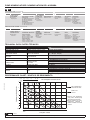
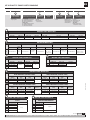
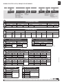
PUMP NOMENCLATURE / NOMENCLATURA DE LA BOMBA
TECHNICAL DATA / DATOS TÉCNICOS
UP10 X -X X X -X X X
UP10 X -X X X -X X X
CENTRAL BODY &
AIR CHAMBERS FLUID PORTS / LOCATION FLUID CHAMBERS
& MANIFOLDS HARDWARE BOLTS VALVE SEATS VALVE BALLS DIAPHRAGM
B Conductive
Polypropylene
Central ports:
C 1” ANSI/DIN Flanged Ports
B 1” BSP Threaded Ports
N 1” NPT Threaded Ports
Lateral ports:
F 1” ANSI/DIN Flanged Ports
P 1” BSP Threaded Ports
T 1” NPT Threaded Ports
P Polypropylene
W PVDF
B Conductive
Polypropylene
S Stainless steel P Polypropylene
T PTFE
H Hytrel®
M Santoprene®
N Nitrile (Buna-N)
T PTFE (Teon®)
V FKM (Viton®)
A Santoprene®
C Hytrel®
G Nitrile (Buna-N)
V FKM (Viton®)
Two-piece:
Z PTFE (Teon® with
Santoprene® backer)
CUERPO CENTRAL Y
CÁMARAS DE AIRE CONEXIONES / UBICACIÓN
CÁMARAS
DE FLUIDO Y
COLECTORES
TORNILLERÍA ASIENTOS BOLAS DIAFRAGMAS
B Polipropileno
conductivo
Puertos centrales:
C Brida 1” ANSI/DIN
B Conex. roscadas 1” BSP
N Conex. roscadas 1” NPT
Puertos laterales:
F Brida 1” ANSI/DIN
P Conex. roscadas 1” BSP
T Conex. roscadas 1” NPT
P Polipropileno
W PVDF
B Polipropileno
Conductivo
S Acero inoxidable P Polipropileno
T PTFE
H Hytrel®
M Santoprene®
N Nitrile (Buna-N)
T PTFE (Teon®)
V FKM (Viton®)
A Santoprene®
C Hytrel®
G Nitrile (Buna-N)
V FKM (Viton®)
Dos piezas:
Z PTFE (Teon® con soporte de
Santoprene®)
PUMP NOMENCLATURE: UP10X-XXX-XXX
NOMENCLATURA DE LA BOMBA : UP10X-XXX-XXX
EN ES
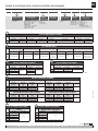
PERFORMANCE CHART / GRÁFICO DE RENDIMIENTO
UP10
RATIO RATIO 1:1
MAXIMUM FREE FLOW MÁXIMO CAUDAL SALIDA LIBRE 200 l/min. (53 Us gal/min)
DELIVERY PER CYCLE DESPLAZAMIENTO POR CICLO 0,85 l. (0,2 gal)
AIR PRESSURE
OPERATING RANGE RANGO DE PRESIÓN 1,5 - 7 bar (20 - 100 psi)
SOLID IN SUSPENSION
MAX SIZE
MAX. TAMAÑO DE PARTÍCULAS
EN SUSPENSIÓN 6,4 mm (1/4”)
MAXIMUM SUCTION HEAD ALTURA MÁXIMA DE SUCCIÓN 5 m (16 ft) dry / 8 m (26 ft) wet
FLUID INLET/OUTLET
CONNECTIONS
CONEXIONES DE
ENTRADA/SALIDA
DE FLUIDO
1" ANSI/DIN DN25 Flanged / Brida
1" BSP (F) Threaded / Roscada
1" NPT (F) Threaded / Roscada
AIR INLET ENTRADA DE AIRE 1/2” NPT (F)
AIR EXHAUST PORT SALIDA DE AIRE 1” NPT (F) (Optional / Opcional)
SOUND LEVEL NIVEL SONORO 75 db (A) @ 50 cycles/ciclos / min @ 5 bar (70 psi)
WEIGHT PESO 10,2 Kg (22.5 lb) - PP Version / Versión PP
11,6 Kg (25.6 lb) - Conductive PP Version / Versión PP conductivo
13,5 Kg (29.8 lb) - PVDF Version / Versión PVDF
0 25 50 75 100 125 150 175 200
0 6.6 13.2 19.8 26.4 33 39.6 46.2 52.8
l/min
US gal/min
bar psi
8
7
6
5
4
3
2
1
0
120
101.5
87
72.5
58
43.5
29
14.5
0
Air consumption / Consumo de aire
Fluid pressure / Presión uido
Pump ow / Caudal
AIR CONSUMPTION
CONSUMO DE AIRE
PUMP FLOW
CAUDAL
*Tested at room temperature,
using water. Flooded pump
with positive suction head.
*Ensayo realizado con agua a
temperatura ambiente y
bomba inundada de succión
positiva.
0 4 15 21 30 38 53
0 2 7 10 14 18 25
scfm
l/sec
2 bar - 30 psi
3 bar - 40 psi
4 bar - 60 psi
5 bar - 70 psi
6 bar - 90 psi
7 bar - 100 psi

3
R. 04/23 855 880
SAMOA Industrial, S.A. · Pol. Ind. Porceyo, I-14 · Camino del Fontán, 831 · 33392 - Gijón - Spain · Tel.: +34 985 381 488 · www.samoaindustrial.com
2023_04_14-08:30
DIMENSIONES (mm)
A B C D E F G H I J
425 415 254 109 214
56
146
399
K L M
128
N
11
133 59 363 280 255
R S
83,5
T
15
77,5
Conexion Lateral
Conexion Central
-
DIMENSIONES (in)
A B C D E F G H I J
16
47/64"
K L M N R S
3
9/32"
T
19/32"
3
3/64"
Conexion Lateral
Conexion Central
-
15
45/64"
16
11/32" 10" 5
15/64"
4
19/64"
2
21/64"
14
19/64"
11
1/32"
10
3/64"
5
3/64" 7/16"
8
27/64"
5
3/4" 2
13/64"
DIMENSIONES (mm)
A B C D E F G H I J
390 254 109 214
40
146
399
K L M
128
N
11
133 59 363 280 255
Conexion Lateral
Conexion Central
-
DIMENSIONES (in)
A B C D E F G H I J K L M N
Conexion Lateral
Conexion Central
-
15
45/64"
16
11/32" 10" 5
15/64"
4
19/64"
2
21/64"
14
19/64"
11
1/32"
10
3/64"
5
3/64" 7/16"
8
27/64"
5
3/4" 1
37/64"
CONEXION DE BRIDA (Central/Lateral)
CONEXION ROSCADA (Central/Lateral)
DIMENSIONES PAG. 3
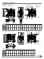
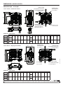
DIMENSIONS / DIMENSIONES
DIMENSIONES (mm)
A B C D E F G H I J
425 415 254 109 214
56
146
399
K L M
128
N
11
133 59 363 280 255
R S
83,5
T
15
77,5
Conexion Lateral
Conexion Central
-
DIMENSIONES (in)
A B C D E F G H I J
16
47/64"
K L M N R S
3
9/32"
T
19/32"
3
3/64"
Conexion Lateral
Conexion Central
-
15
45/64"
16
11/32" 10" 5
15/64"
4
19/64"
2
21/64"
14
19/64"
11
1/32"
10
3/64"
5
3/64" 7/16"
8
27/64"
5
3/4" 2
13/64"
DIMENSIONES (mm)
A B C D E F G H I J
390 254 109 214
40
146
399
K L M
128
N
11
133 59 363 280 255
Conexion Lateral
Conexion Central
-
DIMENSIONES (in)
A B C D E F G H I J K L M N
Conexion Lateral
Conexion Central
-
15
45/64"
16
11/32" 10" 5
15/64"
4
19/64"
2
21/64"
14
19/64"
11
1/32"
10
3/64"
5
3/64" 7/16"
8
27/64"
5
3/4" 1
37/64"
CONEXION DE BRIDA (Central/Lateral)
CONEXION ROSCADA (Central/Lateral)
DIMENSIONES PAG. 3
A B C D E F G H I J K L M N
Lateral Conn.
Conex.Lateral mm
425
415 254 133 109 214 146
-
59 363 280 255 128 11
Central Conn.
Conex.Central 399 56
Lateral Conn.
Conex.Lateral in
16.73”
16.34” 10” 5.24” 4.29” 8.43” 5.75”
-
2.32” 14.29” 11.02” 10.04” 5.04” 0.43”
Central Conn.
Conex.Central 15.71” 2.20”
R S T
77,5 83,5 15
3.05” 3.29” 0.59”
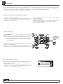
DIMENSIONS / DIMENSIONES
NON-METALLIC / PLÁSTICA
Flanged outlets / Conexión de brida FLUID OUTLET
SALIDA FLUIDO
(FLANGE/BRIDA
DIN DN25/ANSI 1”)
AIR EXHAUST
ESCAPE DE AIRE
FLUID INLET
ENTRADA FLUIDO
(FLANGE/BRIDA
DIN DN25/ANSI 1”)
AIR INLET
ENTRADA AIRE
(1/2” NPT-F)
A B C D E F G H I J K L M N
Lateral Conn.
Conex.Lateral mm 399 386 250 135 108 214 146
-
59 363 280 255 128 11
Central Conn.
Conex.Central 40
Lateral Conn.
Conex.Lateral in 15.71” 15.20” 9.84” 5.31” 4.25” 8.43” 5.75”
-
2.32” 14.29” 11.02” 10.04” 5.04” 0.43”
Central Conn.
Conex.Central 1.57”
DIMENSIONS / DIMENSIONES
Threaded outlets / Salidas roscadas FLUID OUTLET
SALIDA FLUIDO
(1” BSP-F/NPT-F)
FLUID INLET
ENTRADA FLUIDO
(1” BSP-F/NPT-F)
AIR EXHAUST
ESCAPE DE AIRE
AIR INLET
ENTRADA AIRE
(1/2” NPT-F)
B
J
K
I
A
L
M
N
D E
H
ØR
ØS
ØT
B
J
K
I
L
N
M
C
F
G
D E
H
F
G
C

2023_04_14-08:30
EN
4855 880 R. 04/23
SAMOA Industrial, S.A. · Pol. Ind. Porceyo, I-14 · Camino del Fontán, 831 · 33392 - Gijón - Spain · Tel.: +34 985 381 488 · www.samoaindustrial.com
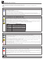
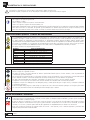
WARNINGS AND CAUTIONS
EQUIPMENT MISUSE
• This equipment is for professional use only.
• Do not tamper the equipment.
• Use the equipment only for its intended purpose.
• Use only original replacement parts from Samoa Industrial, S.A.
• Install and use the pump following all local and national regulations including all health and safety laws and regulations.
• Avoid unnecessary damage to the pump. Do not allow the pump to run for long periods of time without fluid (dry). Disconnect the
pump from the air line when the system is idle for long periods of time.
CHEMICAL COMPATIBILITIES AND TEMPERATURE LIMITS
• Chemical compatibility can change with temperature and concentration of chemicals within the fluids being pumped, discharged or
circulated. For specific fluid compatibility, consult the chemical manufacturer.
• Maximum temperature limits are based upon mechanical stress only. Certain chemicals will significantly reduce maximum safe
operating temperatures. Consult the chemical manufacturer for temperature limits.
• Fluids not compatible with the pump materials can cause damage to the pump and may cause serious personal injuries. Always consult
your authorized Samoa supplier if you have questions regarding the pump and fluid compatibility.
• Do not exceed material temperature limits:
MATERIAL TEMPERATURE RANGE
PTFE -10 °C / +107°C /-14 °F / +225 °F
NBR -23 °C / +82 °C /-10 °F / +180 °F
Acetal -40 °C / +120 °C /-40 °F / +250 °F
Hytrel®-29 °C / +104 °C /-20 °F / +220 °F
Neoprene -18 °C/ +93 °C /0 ºF - 200 ºF
Santoprene®-40 °C / +135 °C /-40 °F / +275 °F
Viton®-40 °C / +177 °C /-40 °F / +350 °F
Polypropylene 0 °C / +65°C /+32 °F / +150 °F
SAFETY MEASURES
• Ensure that operators using this equipment are trained on the operation, the product and its limitations.
• Use safety equipment as required.
• Do not use a model with aluminium wetted parts to pump fluids for human consumption, there is a possibility of trace contamination
of lead.
• Do not exceed the air maximum pressure: 100 psi (7 bar). Make sure that hoses and other components are rated for the pump
maximum working pressure. Check all hoses for damage or wear.
• Never use a pump that leaks, that is damaged, that is corroded or otherwise it may lack the capacity to contain the fluid.
Frequently check that the bolts on the pump fluid covers are correctly torqued.
• Check the diaphragm conditions. If a diaphragm is broken, the fluid can leak out of the air exhaust and cause personnel injuries or
contaminate the environment.
• When handling hazardous fluids, always route the air exhaust into a suitable container and locate it in a safe place. Install a suitable
container surrounding the pump to prevent any leaks or spills.
FIRE AND EXPLOSION HAZARD
• Prevent static sparking. If static sparking occurs, fire or explosion could result. Pump, valves, and containers must be properly grounded
when handling flammable fluids and whenever discharge of static electricity is a hazard.
• Danger of explosion if 1,1,1-trichloroethane, methylene chloride or other halogenated hydrocarbon solvents are used with wetted
parts made from aluminium. It could cause serious injury and property damage. Check the motor section of the pump, fluid covers,
manifolds and all wetted parts in order to ensure compatibility before using these solvents.
• In order to avoid hazardous conditions that can cause fire or explosion all label and marking material must be cleaned to enable
proper reading.
Product pictures and specifications are subject to change without prior notice.
The English version is a translation of the original document in Spanish. In case of a discrepancy, the original will prevail.

2023_04_14-08:30
EN
5
R. 04/23 855 880
SAMOA Industrial, S.A. · Pol. Ind. Porceyo, I-14 · Camino del Fontán, 831 · 33392 - Gijón - Spain · Tel.: +34 985 381 488 · www.samoaindustrial.com
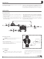
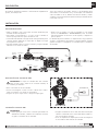
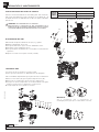
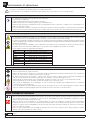
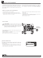
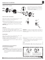
DESCRIPTION
WARNING
• To ensure that the air flow is sufficient to meet the pump
demand, the air pipe diameter must be equal to the pump air
inlet.
AIR CONNECTION
• Install the pump as close as possible to the fluid being pumped to
minimise the suction head.
• For the ease of operation and service, mount the pump so there is
enough space around it.
• If the pump is installed in a place where fluid leakage can cause an
environmental impact, the exhaust should be directed to a place
where it can be contained.
RECOMMENDATIONS
• When installing the pump in its place, use brackets to secure its base.
• Fasten all bolts with the torques contained in this manual (REPAIR AND
MAINTENANCE section). Let the pump running for a whole day. After
that, check the torques again.
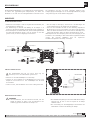
UP pumps can be installed with flooded suction, suction lift or submerged
in the fluid pumped. The figure below shows the recommended
configuration for the pump installation.
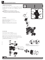
Air operated double diaphragm pumps are air-powered, reciprocating
positive displacement pumps.
INSTALLATION
They have two opposite pump volumes and a diaphragm divides each
volume into an air and a liquid chamber. The diahphragms are connected
with a shaft. During one pumping stroke, the fluid is suctioned into one
of the liquid chambers while simultaneously the other one is discharged.
Discharge
valve
Pressure
gauge
Flexible
connection
1/2”
1/2”
AIR
Shut-off
valve
MAX. 7 BAR
Regulator, filter
1”
SUCTION
Flexible
connection
Vacuum gauge
1”
REMOTE EXHAUST
1” NPT
• Air treatment equipment must be dimensioned to meet pump
air demand. It must be installed as close as possible to the pump
unit.
• Using air quick couplers to connect the air hoses facilitates
pump maintenance.
• Remove the pump air muffler.
• Connect a hose with a 1” NPT thread to the new exhaust port and
install the muffler at the end of the hose.
• Be sure the air exhaust is directed to a safe place.
AIR EXHAUST DISPOSAL
WARNING: The pump exhaust should be directed to a safe
place, away from people, animals and food.
Pulsation dampener

2023_04_14-08:30
EN
6855 880 R. 04/23
SAMOA Industrial, S.A. · Pol. Ind. Porceyo, I-14 · Camino del Fontán, 831 · 33392 - Gijón - Spain · Tel.: +34 985 381 488 · www.samoaindustrial.com
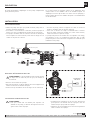
This pump is self-priming. To prime it for the first time connect the pump air inlet to a low air pressure supply. Keep the outlet valve open and gradually
increase the pressure until the fluid comes out of the pump outlet. The air pressure supply must be between 1 and 7 bar (20 and 100 psi). For the
performance characteristics of the pump see the performance chart (TECHNICAL DATA section).
• Shut off the air supply to the pump.
• Check that the air valve is closed.
• Close the discharge valve and the suction valve. Open inlet and outlet
drain valves if installed.
OPERATING INSTRUCTIONS
STOPPING THE PUMP FOR MAINTENANCE TASKS
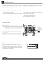
GROUNDING THE PUMP
ATEX CERTIFIED PUMP
GROUND WIRE
CONNECTION POINT
• Open the air valve of the pump, start up the pump and flush the
remaining fluid.
• Close the air valve.
• Maintenance can be started after ensuring that the pump is turned off and
the pressure is released.
• Unground the pump.
When installing the pump, be sure to perform grounding in the specified
location if required.
Also connect ground wires for the auxiliary equipment and piping.
Use a grounding cable of at least 12 AWG (2.0 mm).
If your pump is ATEX certified, a specific Atex manual is included. Read
this manual before operating the pump
If the symbol “Ex” is in the pump nameplate it can be used in the
potentially explosive atmospheres indicated areas (details on the
ATEX manual).
WARNING: If the pump operates ungrounded or with an
incorrect connection, friction between parts and fluid abrasion can
generate static electricity. Depending on the fluid pumped and
the installation environment, static electricity can cause either fire
or electric shock.
MAX. AIR / FLUID PRESSURE:
FLUID IN / OUT:
CODE:
MFG. DATE:
MODEL:
SERIAL No.:
UP10X-XXX-XXX-X
UP10
XX/XX
XXXX XXX
XXXXXXXXX XXX
7 bar / 100 psi
www.samoaindustrial.com
MADE IN SPAIN
PATENTED
0163
II 2G Ex h IIB/IIC T6...T5 Gb
II 2D Ex h IIIB T85ºC...T100ºC Db
MAX. AIR / FLUID PRESSURE:
FLUID IN / OUT:
CODE:
MFG. DATE:
MODEL:
SERIAL No.:
0163
UP10X-XXX-XXX-X
UP10
XX/XX
XXXX XXX
XXXXXXXXX XXX
www.samoaindustrial.com MADE IN SPAIN • PATENTED
7 bar / 100 psi
PERSONALIZACIÓN SAMOA PXXXXXX
BOMBAS DE MEMBRANA UP10 R-09/21
Adhesivo N 449 MARCA SAMOA
Adhesivo N 450 PIVOT SERIES
Adhesivo N 334 SEGURIDAD
CHAPA METÁLICA Características técnicas tamaño 55x24 mm
Vesión CE o ATEX según proceda.
Incluir manual de instrucciones SAMOA
NOMBRE FIRMA FECHA
Relizado por: Maite Pando 29/09/21
Revisado por:
Revisado por:
Aprobado por:
¡ATENCIÓN!
Esta hoja informa exclusivamente sobre la personalización
de imagen y marca del producto.
En el caso de los enrolladores, la colocación o no de la manguera así como la
posición del brazo del enrollador no vendrán determinados nunca por esta hoja.
N 334
Chapas metálicas VERSIÓN CE y ATEX
Se recomienda la utilización de agua para el
pegado de estos adhesivos.
•
R
E
A
D
M
A
N
U
A
L
B
E
F
O
R
E
U
S
E
•
A
i
r
i
n
l
e
t
m
a
x
.
p
r
e
s
s
.
7
b
a
r
1
0
0
p
s
i
STATIC
SPARK MAY CAUSE
EXPLOSION - GROUND PUMP
RETORQUE BOLTS REGULARLY,
TORQUE VALUES IN MANUAL.
EXHAUST MAY PROJECT FLUID
WEAR PROTECTIVE
CLOTHING & MASK
WAR NING !
N449
UNIV ERSAL P U MP
UP Series10
N 449
N 450

2023_04_14-08:30
EN
7
R. 04/23 855 880
SAMOA Industrial, S.A. · Pol. Ind. Porceyo, I-14 · Camino del Fontán, 831 · 33392 - Gijón - Spain · Tel.: +34 985 381 488 · www.samoaindustrial.com
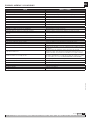
TROUBLESHOOTING
CAUSE RECOMMENDED MEASURE
THE PUMP DOES NOT WORK
Discharge valve on the discharge side is not open. Open the valve on the discharge side.
No air supply. Turn on the compressor and open the air valve and air regulator.
Low air supply pressure. Check the compressor and the air line configuration.
Air leaks in connecting elements. Check the connection elements and screws tightening.
Air pipes or additional equipment is clogged. Check and clean the air line.
Pump exhaust port (muffler) is clogged. Check and clean the exhaust port and muffler.
Fluid pipe is clogged. Check and clean the fluid line.
Clogged pump. Remove, inspect and clean the pump.
THE PUMP RUNS BUT NO FLUID COMES OUT
Valve on the suction side is not open. Open the valve on the suction side.
Too much suction or discharge height. Reduce lengths/heights of suction and discharge pipes.
Fluid pipe on the discharge side (including the filter) is clogged. Check and clean the fluid line.
Clogged pump. Dismantle the pump, check and clean.
Balls and/or ball seats are worn or damaged. Inspect and replace parts.
DECREASING FLOW
Low air supply. Check the compressor and the air line configuration.
Air line or peripheral equipment is clogged. Check and clean the air line.
Valve on the discharge side will not open normally. Adjust the discharge valve on the discharge side.
Air mixes with the fluid. Replenish with fluid and check the pipe configuration on the suction side.
Pump is vibrating.
Adjust air supply pressure and discharge pressure. Reduce the inlet valve
flow to adjust the pressure and fluid volume. Securely fix the pump with
the bracket to the base.
Ice formation in the air exhaust.
Remove ice from the air bypass valve and check and clean the air filter.
Use a pipe in the air exhaust so there is no ice formation in the muffler
(see AIR EXHAUST DISPOSAL).
Fluid line (including the filter) is clogged. Check and clean the fluid pipe and strainer.
Pump exhaust port (muffler) is clogged. Check and clean the exhaust port and muffler.
Clogged pump. Remove, inspect and clean the pump body.
THE FLUID COMES OUT WITH AIR BUBBLES
Damaged diaphragm. Replace diaphragm.
Loose or broken suction hose. Tighten or replace.

2023_04_14-08:30
EN
8855 880 R. 04/23
SAMOA Industrial, S.A. · Pol. Ind. Porceyo, I-14 · Camino del Fontán, 831 · 33392 - Gijón - Spain · Tel.: +34 985 381 488 · www.samoaindustrial.com
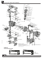
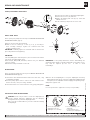
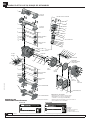
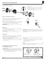
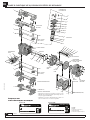
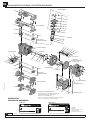
AIR CAP
OUTLET
MANIFOLD
BALLS
SOFT SEATS
(NO SEALS)
SOFT SEATS
(NO SEALS)
BALLS
AIR
EXHAUST
CENTRAL
BODY
AIR SHAFT
AIR SENSOR
DIAPHRAGM
(NBR, SANTOPRENE,
HYTREL, FKM)
FLUID
PISTON
FLUID
COVER
INLET MANIFOLD
2
3
4
5
7
6
3
4
8
13
14
15
16
17
18
19
17
20
21
12
11
22 23 24 25 22 26
27
28
29
30
31
32
AIR
COVER
AIR
PISTON
33
34
38 39
35
36
37
DIAPHRAGM (PTFE)
10
AIR VALVE
1
9
UP10-PLASTICO+PLASTICO
UP1002_kits_de_recambios-plastico_FLOW
PROYECTO: P-55-010-18
23/01/2023
UP10 PLASTIC PUMP PARTS DRAWING
LUBRICATION / SEALANTS
- Apply mounting grease to all O-ring.
- Apply medium strength sealing to threards
at assembly (type LOCTITE 243).
- Apply anti-seize compound to threads when using
stainless steel fasteners.
CE Version
MAX. AIR / FLUID PRESSURE:
FLUID IN / OUT:
CODE:
MFG. DATE:
MODEL:
SERIAL No.:
UP10X-XXX-XXX-X
UP10
XX/XX
XXXX XXX
XXXXXXXXX XXX
7 bar / 100 psi
www.samoaindustrial.com
MADE IN SPAIN
PATENTED
0163
II 2G Ex h IIB/IIC T6...T5 Gb
II 2D Ex h IIIB T85ºC...T100ºC Db
MAX. AIR / FLUID PRESSURE:
FLUID IN / OUT:
CODE:
MFG. DATE:
MODEL:
SERIAL No.:
0163
UP10X-XXX-XXX-X
UP10
XX/XX
XXXX XXX
XXXXXXXXX XXX
www.samoaindustrial.com MADE IN SPAIN • PATENTED
7 bar / 100 psi
PERSONALIZACIÓN SAMOA PXXXXXX
BOMBAS DE MEMBRANA UP10 R-09/21
Adhesivo N 449 MARCA SAMOA
Adhesivo N 450 PIVOT SERIES
Adhesivo N 334 SEGURIDAD
CHAPA METÁLICA Características técnicas tamaño 55x24 mm
Vesión CE o ATEX según proceda.
Incluir manual de instrucciones SAMOA
NOMBRE FIRMA FECHA
Relizado por: Maite Pando 29/09/21
Revisado por:
Revisado por:
Aprobado por:
¡ATENCIÓN!
Esta hoja informa exclusivamente sobre la personalización
de imagen y marca del producto.
En el caso de los enrolladores, la colocación o no de la manguera así como la
posición del brazo del enrollador no vendrán determinados nunca por esta hoja.
N 334
Chapas metálicas VERSIÓN CE y ATEX
Se recomienda la utilización de agua para el
pegado de estos adhesivos.
•
R
E
A
D
M
A
N
U
A
L
B
E
F
O
R
E
U
S
E
•
A
i
r
i
n
l
e
t
m
a
x
.
p
r
e
s
s
.
7
b
a
r
1
0
0
p
s
i
STATIC
SPARK MAY CAUSE
EXPLOSION - GROUND PUMP
RETORQUE BOLTS REGULARLY,
TORQUE VALUES IN MANUAL.
EXHAUST MAY PROJECT FLUID
WEAR PROTECTIVE
CLOTHING & MASK
WAR NING !
N449
UNIV ERSAL P U MP
UP Series10
N 449
N 450
MODEL:
5XXXXX
(numerical coding)
UP10X-XXX-XXX
(alphanumeric coding)
ATEX Version
MAX. AIR / FLUID PRESSURE:
FLUID IN / OUT:
CODE:
MFG. DATE:
MODEL:
SERIAL No.:
UP10X-XXX-XXX-X
UP10
XX/XX
XXXX XXX
XXXXXXXXX XXX
7 bar / 100 psi
www.samoaindustrial.com
MADE IN SPAIN
PATENTED
0163
II 2G Ex h IIB/IIC T6...T5 Gb
II 2D Ex h IIIB T85ºC...T100ºC Db
MAX. AIR / FLUID PRESSURE:
FLUID IN / OUT:
CODE:
MFG. DATE:
MODEL:
SERIAL No.:
0163
UP10X-XXX-XXX-X
UP10
XX/XX
XXXX XXX
XXXXXXXXX XXX
www.samoaindustrial.com MADE IN SPAIN • PATENTED
7 bar / 100 psi
PERSONALIZACIÓN SAMOA PXXXXXX
BOMBAS DE MEMBRANA UP10 R-09/21
Adhesivo N 449 MARCA SAMOA
Adhesivo N 450 PIVOT SERIES
Adhesivo N 334 SEGURIDAD
CHAPA METÁLICA Características técnicas tamaño 55x24 mm
Vesión CE o ATEX según proceda.
Incluir manual de instrucciones SAMOA
NOMBRE FIRMA FECHA
Relizado por: Maite Pando 29/09/21
Revisado por:
Revisado por:
Aprobado por:
¡ATENCIÓN!
Esta hoja informa exclusivamente sobre la personalización
de imagen y marca del producto.
En el caso de los enrolladores, la colocación o no de la manguera así como la
posición del brazo del enrollador no vendrán determinados nunca por esta hoja.
N 334
Chapas metálicas VERSIÓN CE y ATEX
Se recomienda la utilización de agua para el
pegado de estos adhesivos.
•
R
E
A
D
M
A
N
U
A
L
B
E
F
O
R
E
U
S
E
•
A
i
r
i
n
l
e
t
m
a
x
.
p
r
e
s
s
.
7
b
a
r
1
0
0
p
s
i
STATIC
SPARK MAY CAUSE
EXPLOSION - GROUND PUMP
RETORQUE BOLTS REGULARLY,
TORQUE VALUES IN MANUAL.
EXHAUST MAY PROJECT FLUID
WEAR PROTECTIVE
CLOTHING & MASK
WAR NING !
N449
UNIV ERSAL P U MP
UP Series10
N 449
N 450
TECHNICAL
CHARACTERISTICS LABEL

2023_04_14-08:30
EN
9
R. 04/23 855 880
SAMOA Industrial, S.A. · Pol. Ind. Porceyo, I-14 · Camino del Fontán, 831 · 33392 - Gijón - Spain · Tel.: +34 985 381 488 · www.samoaindustrial.com
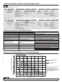
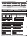
AIR MOTOR REPAIR KITS
AIR EXHAUST AIR SHAFT SEALS AIR VALVE AIR SENSOR
Kit Code Incl.
Pos. Kit Code Incl. Pos. Kit Code Incl. Pos. Kit Code Incl. Pos. Kit Code Incl. Pos.
BUP10R-AM-500 5, 6,
4X(7) UP10R-AM-300 28, 2x(29),
2x(30), UP10R-WP-400
14, 2x(17),
18, 20, 21,
2x(30), 2x(31)
UP10R-AM-1A0 2x(17), 19,
20 ,21 UP10R-AM-201
4x(22), 2x(23),
2x(24), 2x(25),
2x(26), 4x(27)
HOUSING PARTS REPAIR KITS
FLUID PISTON FLUID COVER
Kit Code Incl. Pos. Kit Code Incl. Pos.
PUP10R-HP-7P0
2x(38)
UP10R-HP-3P0
39BUP10R-HP-7B0 UP10R-HP-3B0
WUP10R-HP-7W0 UP10R-HP-3W0
HOUSING PARTS REPAIR KITS
INLET MANIFOLD (CENTRAL PORT) INLET MANIFOLD (LATERAL PORT)
Kit Code
(Flange)
Kit Code
(BSP)
Kit Code
(NPT) Incl. Pos. Kit Code
(Flange)
Kit Code
(BSP)
Kit Code
(NPT) Incl. Pos.
PUP10R-HP-1PC UP10R-HP-1PB UP10R-HP-1PN
9
UP10R-HP-1PF UP10R-HP-1PP UP10R-HP-1PNT
8
BUP10R-HP-1BC UP10R-HP-1BB UP10R-HP-1BN UP10R-HP-1BF UP10R-HP-1BP UP10R-HP-1BT
WUP10R-HP-1WC UP10R-HP-1WB UP10R-HP-1WN UP10R-HP-1WF UP10R-HP-1WP UP10R-HP-1WT
OUTLET MANIFOLD (CENTRAL PORT) OUTLET MANIFOLD (LATERAL PORT)
Kit Code
(Flange)
Kit Code
(BSP)
Kit Code
(NPT) Incl. Pos. Kit Code
(Flange)
Kit Code
(BSP)
Kit Code
(NPT) Incl. Pos.
PUP10R-HP-2PC UP10R-HP-2PB UP10R-HP-2PN
1
UP10R-HP-2PF UP10R-HP-2PP UP10R-HP-2PT
2
BUP10R-HP-2BC UP10R-HP-2BB UP10R-HP-2BN UP10R-HP-2BF UP10R-HP-2BP UP10R-HP-2BT
WUP10R-HP-2WC UP10R-HP-2WB UP10R-HP-2WN UP10R-HP-2WF UP10R-HP-2WP UP10R-HP-2WT
WETTED PARTS REPAIR KITS
BALLS
Kit Code Incl. Pos.
HUP10R-WP-0H0
4x(3)
MUP10R-WP-0M0
NUP10R-WP-0N0
TUP10R-WP-0S0
VUP10R-WP-0V0
HOUSING PARTS REPAIR KITS
CENTRAL BODY AIR COVER AIR CAP AIR PISTON
Kit Code Incl. Pos. Kit Code Incl. Pos. Kit Code Incl. Pos. Kit Code Incl. Pos.
BUP10R-HP-5B0 10 UP10R-HP-4B0 32 UP10R-HP-8B0 6x(11), 6x(12), 13, 14, 15, 2x(16), 17, 18 UP10R-HP-6S0 2x(33)
1
1
3
UP10 PLASTIC PUMP PARTS DRAWING
3
5
UP10 X -X X X -X X X
CENTRAL BODY
& AIR CHAMBERS FLUID PORTS & LOCATION FLUID CHAMBERS
& MANIFOLDS
HARDWARE
BOLTS VALVE SEATS VALVE BALLS DIAPHRAGM
B Conductive
Polypropylene
Central ports:
C 1” ANSI/DIN Flanged Ports
B 1” BSP Threaded Ports
N 1” NPT Threaded Ports
Lateral ports:
F 1” ANSI/DIN Flanged Ports
P 1” BSP Threaded Ports
T 1” NPT Threaded Ports
P Polypropylene
W PVDF
B Conductive
Polypropylene
S Stainless steel P Polypropylene
T PTFE
H Hytrel®
M Santoprene®
N Nitrile (Buna-N)
T PTFE (Teon®)
V FKM (Viton®)
A Santoprene®
C Hytrel®
G Nitrile (Buna-N)
V FKM (Viton®)
Two-piece:
Z PTFE (Teon® with
Santoprene® backer)
1 3 4 5 6
* Available as kit UP10R-WP-999 (contains 8 PTFE O-rings).
WETTED PARTS REPAIR KITS
SEATS
PTFE Seals Kit Code Incl. Pos.
PT* UP10R-WP-A00 4x(4)
NT* UP10R-WP-N00
4
WETTED PARTS REPAIR KITS
TWO PIECE DIAPHRAGMS
Kit Code Incl. Pos.
CUP10R-WP-00A
2x(34)
AUP10R-WP-00C
GUP10R-WP-00G
VUP10R-WP-00V
ZUP10R-WP-00Z 2x(35), 2x(36), 2x(37)
6

2023_04_14-08:30
EN
10 855 880 R. 04/23
SAMOA Industrial, S.A. · Pol. Ind. Porceyo, I-14 · Camino del Fontán, 831 · 33392 - Gijón - Spain · Tel.: +34 985 381 488 · www.samoaindustrial.com
For proper pump operation and to prevent accidents, you must
periodically review the torques of the diaphragms covers and the
directional valve. The table shows the appropriate torques for
this purpose:
TORQUES
UP10
Cover and manifolds 25 N·m (18 ft.lbs)
Air cap 15 N·m (11 ft.lbs)
Diaphragms 40 N·m (30 ft.lbs)
TORQUE SPECIFICATIONS
CAUTION!: DO NOT OVERTIGHTEN FASTENERS.
SHUT OFF THE AIR SUPPLY BEFORE ANY INTERVENTION.
BE AWARE OF A POSSIBLE FLUID LEAKAGE INSIDE THE PUMP.
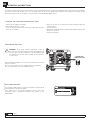
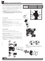
AIR VALVE
1. Unscrew the air cap (12, 13) and remove it.
2. Pull out the air valve (19).
3. Place the bottom gasket (21) in the new air valve.
4. Insert the new air valve.
5. Place the “air cap” with the gaskets in its housing.
6. Tighten the screws with 15 N·m (11 ft.lbs) torque.
AIR SENSOR
The air sensors are on the central body.
First follow the procedure for “Replacing diaphragms”.
Once the fluid covers are removed proceed as follows:
1. Remove the two screws (27) that secure the air sensor to the top.
2. Remove all sensor components (22, 23, 24, 25, 26). Clean the area.
3. Insert new components in the order shown. Assemble the remaining
components in reverse order.
4. Fit the sensor cover (26) and tighten the screws (27).
IMPORTANT:
Follow the diaphragm maintenance procedure to ensure
no damage in the diaphragm during its assembly.
ATTENTION! TIGHTENING SEQUENCE
10 7
3
1
5
9
8
4
2
6
10 7
REPAIR AND MAINTENANCE
12
13
19
21
22 23 24 25 22 26 27

2023_04_14-08:30
EN
11
R. 04/23 855 880
SAMOA Industrial, S.A. · Pol. Ind. Porceyo, I-14 · Camino del Fontán, 831 · 33392 - Gijón - Spain · Tel.: +34 985 381 488 · www.samoaindustrial.com
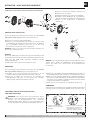
DIAPHRAGM
CAUTION: Follow next procedure to ensure the diaphragms are
correctly installed. Otherwise diaphragms may be damaged,
causing fluid leaks or premature diaphragm failure.
Please note this recommendation if you notice leaks after installing
the diaphragm.
1. Correct assembly of the
diaphragm before the
diaphragm cover assembly.
2. Incorrect assembly of the
diaphragm.
Possible damage when
assembling the diaphragm cover.
CAUTION!
Before opening the pump follow the steps in STOPPING THE PUMP FOR
MAINTENANCE TASKS (page 6).
1. Unscrew the outlet manifold and lift it. Remove the valve seats, o-ring
(if applicable) and balls.
2.Turn the pump upside down to remove the inlet manifold screws.
Remove the seats, seals (if necessary) and balls.
3. Unscrew the fluid cover screws and remove it by gently pulling back.
NOTE:
Use a torque wrench to tighten the screws (see torques table).
INSTALLING NEW DIAPHRAGMS
BALLS AND SEATS
Before opening the pump follow the steps in STOPPING THE PUMP FOR
MAINTENANCE TASKS (page 6).
1. Remove the inlet and outlet manifolds.
2. Install a new set of balls (2) or seats (3) or (4, 5) according to
these assembly drawings. Tighten the manifold bolts with
25 N·m (18 ft.lbs) torque.
IMPORTANT: Gradually tighten the manifold with the bolts before
proceeding with the final tightening.
IMPORTANT:
Soft seats (NBR, Hytrel® and Santoprene®) don’t need extra seals and the
seats can be assembled upside down.
Hard seats (PP, POM, PVDF, aluminum, stainless steel), use additional
o-rings for sealing.
Balls must be always assembled over the seat.
IMPORTANT: If the pump maintenance involves disassembling the
manifolds and the pump is configured with PTFE o-rings (white colour),
they must be replaced by new ones in order to avoid
fluid leakages.
4. Remove the used diaphragm. For one-piece diaphragms unscrew by
pulling with the hand. In case of two-piece diaphragms (diaphragm with
outer piston) use an adjustable wrench and apply corresponding torque.
5. Repeat for opposite side.
First follow the procedure for “Replacing diaphragms”.
1. Unscrew the air cover (32) and lift it.
2. Replace the bushing and seals (29, 30). Clean and
lubricate the area.
3. Fit the remaining components in reverse order.
SHAFT, BUSHINGS AND SEALS
REPAIR AND MAINTENANCE
This side
to air
chamber
30 29
29 30
32
Soft Seat
32
4
5
Seals

2023_04_14-08:30
EN
12 855 880 R. 04/23
SAMOA Industrial, S.A. · Pol. Ind. Porceyo, I-14 · Camino del Fontán, 831 · 33392 - Gijón - Spain · Tel.: +34 985 381 488 · www.samoaindustrial.com
ES ADVERTENCIAS Y PRECAUCIONES
USO INDEBIDO DEL EQUIPO
• Este equipo es sólo para uso profesional.
• No modifique el equipo.
• Utilice el equipo sólo para el uso para el cual fue diseñado.
• Utilice solo repuestos originales de Samoa Industrial, S.A.
• Instale y utilice la bomba de acuerdo con todas las normativas locales y nacionales incluyendo leyes y regulaciones en materia de salud y seguridad.
• Evite daños innecesarios en la bomba. No permita que la bomba funcione durante largos períodos de tiempo sin fluido (en seco).
Desconecte la bomba de la línea de aire cuando el sistema esté inactivo durante largos períodos de tiempo.
COMPATIBILIDADES QUÍMICAS Y LÍMITES DE TEMPERATURA
• La compatibilidad química puede cambiar con la temperatura y la concentración de los productos químicos en los fluidos que se
bombean, descargan o circulan. Para conocer la compatibilidad específica de los fluidos consulte al fabricante del producto químico.
• Los límites máximos de temperatura se basan únicamente en propiedades mecánicas. Algunos productos químicos pueden reducir
significativamente las temperaturas máximas de funcionamiento. Consulte los límites de temperatura con el fabricante del producto químico.
• Los fluidos no compatibles con los materiales de la bomba pueden causar daños a la misma y provocar graves lesiones personales.
Consulte siempre a su proveedor SAMOA autorizado si tiene dudas sobre la compatibilidad de la bomba y los fluidos.
• No superar los límites de temperatura del material:
MATERIAL RANGO DE TEMPERATURA
PTFE -10 °C / +107°C /-14 °F / +225 °F
NBR -23 °C / +82 °C /-10 °F / +180 °F
Acetal -40 °C / +120 °C /-40 °F / +250 °F
Hytrel®-29 °C / +104 °C /-20 °F / +220 °F
Neoprene -18 °C/ +93 °C /0 ºF - 200 ºF
Santoprene®-40 °C / +135 °C /-40 °F / +275 °F
Viton®-40 °C / +177 °C /-40 °F / +350 °F
Polipropileno 0 °C / +65°C /+32 °F / +150 °F
MEDIDAS DE SEGURIDAD
• Asegúrese de que los operarios que utilicen este equipo estén formados sobre el funcionamiento, el producto y sus limitaciones.
• Utilizar el equipo de seguridad necesario.
• No utilice un modelo con partes húmedas de aluminio para bombear fluidos para el consumo humano, existe la posibilidad de
contaminación por trazas de plomo.
• No exceda la presión máxima del aire: 100 psi (7 bar). Asegúrese de que las mangueras y otros componentes sean adecuados para la
presión máxima de trabajo de la bomba. Compruebe que todas las mangueras no estén dañadas o desgastadas.
• No utilice nunca una bomba que tenga fugas, esté dañada, con marcas de corrosión o presente cualquier anomalía.
• Compruebe con frecuencia que los tornillos de las carcasas del fluido de la bomba están correctamente apretados.
• Compruebe el estado de los diafragmas. Si un diafragma está roto, el fluido puede salir por el escape de aire y contaminar el ambiente
y causar daños personales.
• Cuando manipule fluidos peligrosos, dirija siempre el escape de aire a un contenedor adecuado y ubíquelo en un lugar seguro. Instale
un contenedor adecuado alrededor de la bomba para evitar cualquier fuga o derrame.
RIESGO DE INCENDIO Y EXPLOSIÓN
• Evite las chispas de electricidad estática. Si se producen podría producirse un incendio o una explosión. La bomba, las válvulas y los
contenedores deben estar debidamente conectados a tierra cuando se manipulen fluidos inflamables y siempre que la descarga de
electricidad estática constituya un peligro.
• Peligro de explosión si se utilizan 1,1,1-tricloroetano, cloruro de metileno u otros disolventes de hidrocarburos halogenados con partes
húmedas de aluminio. Podría causar lesiones graves y daños materiales. Compruebe la sección del motor de la bomba, las carcasas
del fluido, los colectores y todas las partes húmedas para garantizar la compatibilidad antes de utilizar estos disolventes.
• Para evitar condiciones peligrosas que puedan causar un incendio o una explosión, todo el material etiquetado y marcado debe
limpiarse para permitir una lectura adecuada.
Las imágenes y especificaciones de los productos están sujetas a cambios sin previo aviso.
Documento original en español. En caso de discrepancia en las traducciones, prevalecerá la versión original.

2023_04_14-08:30
EN
13
R. 04/23 855 880
SAMOA Industrial, S.A. · Pol. Ind. Porceyo, I-14 · Camino del Fontán, 831 · 33392 - Gijón - Spain · Tel.: +34 985 381 488 · www.samoaindustrial.com
ES
ADVERTENCIA
• Para asegurar que el flujo de aire es suficiente para satisfacer la
demanda de la bomba, el diámetro de la tubería de aire debe
ser igual a la entrada de aire de la bomba.
CONEXIÓN TOMA DE AIRE
ESCAPE REMOTO
1” NPT
• Instale la bomba lo más cerca posible del fluido bombeado para
minimizar la altura de aspiración.
• Para facilitar el funcionamiento y el servicio, monte la bomba de
manera que haya suficiente espacio alrededor de ella.
• Si la bomba está instalada en un lugar donde una fuga de fluido puede
causar un impacto ambiental, el escape debe ser dirigido a un lugar
donde pueda ser contenido.
• Para fijar la bomba, utilice los soportes en la base y asegure la bomba
fijándola con los tornillos de amarre.
RECOMENDACIONES
• Apriete todos los tornillos con el par recomendado en este manual
(sección de REPARACIÓN Y MANTENIMIENTO). Deje la bomba
funcionando durante un día entero. Al día siguiente, compruebe los
pares de apriete.
Las bombas UP pueden instalarse con aspiración bajo carga, aspiración
en altura o completamente sumergidas en el fluido bombeado. La figura
siguiente muestra la configuración recomendada para la instalación
de la bomba.
La bomba de membrana neumática es una bomba de desplazamiento
positivo, accionada por aire.
INSTALACIÓN
Tienen dos volúmenes de bombeo opuestos y una membrana divide
cada volumen en una cámara de aire y otra de líquido. Las membranas
están conectadas con un eje. Durante una carrera de bombeo, el fluido
es aspirado en una de las cámaras de líquido mientras que simultáneamente
se descarga en la otra.
DESCRIPCIÓN
Válvula de
impulsión Manómetro
Conexión
flexible
Amortiguador de pulsos
1/2”
1/2”
AIRE
Llave
de paso
MAX. 8 BAR
Regulador, filtro
1”
SUCCIÓN
Conexión
flexible
Vacuómetro
1”
• El equipo de tratamiento de aire debe estar dimensionado para
satisfacer la demanda de aire de la bomba. Debe instalarse lo
más cerca posible de la misma.
• El uso de acoplamientos rápidos para conectar las mangueras
de aire facilita el mantenimiento de la bomba.
• Retire el silenciador de aire de la bomba.
• Conecte una manguera con una rosca de 1” NPT al nuevo escape e
instale el silenciador en el extremo de la manguera.
• Asegúrese de que el escape de aire se dirige a un lugar seguro.
DISPOSICIÓN DEL ESCAPE DE AIRE
ADVERTENCIA: El escape de la bomba debe estar orientado
hacia un lugar seguro, alejado de la circulación humana, de
animales y de alimentos.

2023_04_14-08:30
EN
14 855 880 R. 04/23
SAMOA Industrial, S.A. · Pol. Ind. Porceyo, I-14 · Camino del Fontán, 831 · 33392 - Gijón - Spain · Tel.: +34 985 381 488 · www.samoaindustrial.com
ES MODO DE OPERACIÓN
Esta bomba es autocebante. Para cebarla por primera vez, conecte la
entrada de aire de la bomba al suministro de aire. Abra la válvula de salida
e incremente gradualmente la presión de aire hasta que el fluido empiece
a fluir. Ajuste la presión de aire a la presión requerida.
• Corte el suministro de aire a la bomba.
• Por razones de seguridad, compruebe que la válvula de aire está cerrada.
• Cierre las válvulas de aspiración y descarga. Abra las válvulas de drenaje
de entrada y salida, si las hay.
PARADA DE LA BOMBA PARA TAREAS DE MANTENIMIENTO
CONEXIÓN A TIERRA
BOMBAS CON CERTIFICACIÓN ATEX
PUNTO DE
CONEXIÓN DEL
CABLE A TIERRA
• Abra la válvula de aire de la bomba, ponga en funcionamiento la
bomba y descargue el fluido remanente.
• Cierre la válvula de aire.
• El mantenimiento puede iniciarse después de asegurarse de que la bomba
está desconectada y se ha liberado la presión.
• Desconecte la bomba de la conexión a tierra.
Cuando instale la bomba, asegúrese de realizar la conexión a tierra en
el lugar especificado.
Conecte también conductores a tierra para los equipos auxiliares y
las tuberías.
Utilice un cable con conexión a tierra de por lo menos 12 AWG (2,0 mm).
Si la bomba que ha adquirido está certificada ATEX, a este manual lo
acompañará uno específico para ATEX. Lea este manual antes de operar
con la bomba.
Si el símbolo “Ex” figura en la placa de características de la bomba, ésta
puede utilizarse en las zonas indicadas de atmósferas potencialmente
explosivas (detalles en el manual ATEX).
ADVERTENCIA: Si la bomba opera sin conexión a tierra o con
una conexión incorrecta, la fricción entre las piezas y la abrasión
del fluido pueden generar electricidad estática. Dependiendo del
fluido bombeado y del entorno de la instalación, la electricidad
estática puede provocar un incendio o una descarga eléctrica.
MAX. AIR / FLUID PRESSURE:
FLUID IN / OUT:
CODE:
MFG. DATE:
MODEL:
SERIAL No.:
UP10X-XXX-XXX-X
UP10
XX/XX
XXXX XXX
XXXXXXXXX XXX
7 bar / 100 psi
www.samoaindustrial.com
MADE IN SPAIN
PATENTED
0163
II 2G Ex h IIB/IIC T6...T5 Gb
II 2D Ex h IIIB T85ºC...T100ºC Db
MAX. AIR / FLUID PRESSURE:
FLUID IN / OUT:
CODE:
MFG. DATE:
MODEL:
SERIAL No.:
0163
UP10X-XXX-XXX-X
UP10
XX/XX
XXXX XXX
XXXXXXXXX XXX
www.samoaindustrial.com MADE IN SPAIN • PATENTED
7 bar / 100 psi
PERSONALIZACIÓN SAMOA PXXXXXX
BOMBAS DE MEMBRANA UP10 R-09/21
Adhesivo N 449 MARCA SAMOA
Adhesivo N 450 PIVOT SERIES
Adhesivo N 334 SEGURIDAD
CHAPA METÁLICA Características técnicas tamaño 55x24 mm
Vesión CE o ATEX según proceda.
Incluir manual de instrucciones SAMOA
NOMBRE FIRMA FECHA
Relizado por: Maite Pando 29/09/21
Revisado por:
Revisado por:
Aprobado por:
¡ATENCIÓN!
Esta hoja informa exclusivamente sobre la personalización
de imagen y marca del producto.
En el caso de los enrolladores, la colocación o no de la manguera así como la
posición del brazo del enrollador no vendrán determinados nunca por esta hoja.
N 334
Chapas metálicas VERSIÓN CE y ATEX
Se recomienda la utilización de agua para el
pegado de estos adhesivos.
•
R
E
A
D
M
A
N
U
A
L
B
E
F
O
R
E
U
S
E
•
A
i
r
i
n
l
e
t
m
a
x
.
p
r
e
s
s
.
7
b
a
r
1
0
0
p
s
i
STATIC
SPARK MAY CAUSE
EXPLOSION - GROUND PUMP
RETORQUE BOLTS REGULARLY,
TORQUE VALUES IN MANUAL.
EXHAUST MAY PROJECT FLUID
WEAR PROTECTIVE
CLOTHING & MASK
WAR NING !
N449
UNIV ERSAL P U MP
UP Series10
N 449
N 450
El suministro de aire a presión debe estar entre 1 y 8 bar ( 20 y 120 psi).
Para ver las características de rendimiento de la bomba consulte el grafico
de rendimiento (sección DATOS TÉCNICOS).

2023_04_14-08:30
EN
15
R. 04/23 855 880
SAMOA Industrial, S.A. · Pol. Ind. Porceyo, I-14 · Camino del Fontán, 831 · 33392 - Gijón - Spain · Tel.: +34 985 381 488 · www.samoaindustrial.com
ES
POSIBLES AVERÍAS Y SOLUCIONES
CAUSA MEDIDA A TOMAR
LA BOMBA NO FUNCIONA
La válvula de impulsión en el lado de descarga no está abierta. Abra la válvula de impulsión en el lado de descarga.
No llega aire. Encienda el compresor y abra la válvula de aire y el regulador de aire.
La presión de suministro de aire es baja. Revise el compresor y la configuración de la tubería de aire.
Fugas de aire en elementos de conexión. Revise los elementos de conexión y el apriete de los tornillos.
La tubería de aire o el equipo auxiliar está obstruido. Revise y limpie la tubería de aire.
El orificio de escape (silenciador) de la bomba está obstruido. Revise y limpie el orificio de escape y el silenciador.
La tubería de fluido está obstruida. Revise y limpie la tubería de fluido.
La bomba está obstruida. Desmonte, revise y limpie la bomba.
LA BOMBA FUNCIONA PERO EL FLUIDO NO SALE
La válvula en el lado de succión no está abierta. Abra la válvula en el lado de succión.
Demasiada altura de aspiración o altura de descarga. Reduzca la altura/ longitud de las tuberías de carga y descarga.
La tubería de fluido del lado de descarga (incluido el filtro) está obstruida
con lodo.
Revise y limpie la tubería de fluido.
La bomba está obstruida. Desmonte la bomba, revísela y límpiela.
Las bolas y/o los asientos de las bolas están desgastados o dañados. Revise y reemplace piezas defectuosas.
EL FLUJO ESTÁ DISMINUYENDO
La presión de suministro de aire es baja. Revise el compresor y la configuración de la tubería de aire.
La tubería de aire o el equipo periférico está obstruido. Revise y limpie la tubería de aire.
La válvula de impulsión del lado de descarga no se abre normalmente. Ajuste la válvula de impulsión del lado de descarga.
El aire se mezcla con el fluido. Vuelva a llenar de fluido y revise la configuración de la tubería del lado
de succión.
Se producen vibraciones.
Ajuste la presión de suministro de aire y la presión de descarga.
Disminuya el flujo de la válvula de entrada para ajustar la presión y el
volumen de fluido. Fije firmemente la bomba con el soporte a la base.
Formación de hielo en el escape de aire.
Elimine el hielo de la válvula de desvío de aire y revise y limpie el filtro de
aire. Utilice una tubería en el escape de aire para que el hielo no se forme
en el silenciador (ver sección de DISPOSICIÓN DEL ESCAPE DE AIRE).
La tubería de fluido (incluido el filtro) está obstruida. Revise y limpie la tubería de fluido y el filtro.
El orificio de escape (silenciador) de la bomba está obstruido. Revise y limpie el orificio de escape y el silenciador.
La bomba está obstruida. Desmonte, revise y limpie la bomba.
EL FLUIDO SALE CON BURBUJAS DE AIRE
Membrana dañada. Sustituya la membrana.
Manguera de succión suelta o rota. Apriete o sustituya.

2023_04_14-08:30
EN
16 855 880 R. 04/23
SAMOA Industrial, S.A. · Pol. Ind. Porceyo, I-14 · Camino del Fontán, 831 · 33392 - Gijón - Spain · Tel.: +34 985 381 488 · www.samoaindustrial.com
ES
ASIENTOS DUROS
+ JUNTAS
SENSOR DE AIRE
DIAFRAGMA
(NBR, SANTOPRENE,
HYTREL, FKM)
2
3
6
8
10
9
3
5
11
17
18
19
20
21
22
23
21
25
26
16
15
27 28 29 30 27 31 32
33
34 35
36
37
38
39
42
43
40
41
7
14
1
12
5
7
6
7
24
13
4
4
UP10-PLASTICO+PLASTICO
UP1002_kits_de_recambios-plastico_FLOW
PROYECTO: P-55-011-18
23/03/2023
TAPA DE LA VÁLVULA DE AIRE
COLECTOR
DE SALIDA
COLECTOR
DE SALIDA
BOLAS
ASIENTOS BLANDOS
(SIN JUNTAS)
VÁLVULA DE AIRE
CUERPO CENTRAL
EJE DE AIRE
ESCAPE
DE AIRE
ASIENTOS DUROS
+ JUNTAS
BOLAS
ASIENTOS BLANDOS
(SIN JUNTAS)
COLECTOR DE ENTRADA
COLECTOR DE ENTRADA
PISTÓN
DE FLUIDO
TAPA
DE FLUIDO
TAPA
DE AIRE
PISTÓN
DE AIRE
DIAFRAGMA (PTFE)
BOMBA PLÁSTICA UP10, DIBUJO DE RECAMBIOS
LUBRICACIÓN / SELLADORES
- Aplicar grasa de montaje a todas las juntas.
- Aplicar fijador de resistencia media para
el sellado de roscas (tipo LOCTITE 243).
- Aplicar compuesto antigripaje a las roscas cuando se
usen tornillos de acero inoxidable.
Versión CE
MAX. AIR / FLUID PRESSURE:
FLUID IN / OUT:
CODE:
MFG. DATE:
MODEL:
SERIAL No.:
UP10X-XXX-XXX-X
UP10
XX/XX
XXXX XXX
XXXXXXXXX XXX
7 bar / 100 psi
www.samoaindustrial.com
MADE IN SPAIN
PATENTED
0163
II 2G Ex h IIB/IIC T6...T5 Gb
II 2D Ex h IIIB T85ºC...T100ºC Db
MAX. AIR / FLUID PRESSURE:
FLUID IN / OUT:
CODE:
MFG. DATE:
MODEL:
SERIAL No.:
0163
UP10X-XXX-XXX-X
UP10
XX/XX
XXXX XXX
XXXXXXXXX XXX
www.samoaindustrial.com MADE IN SPAIN • PATENTED
7 bar / 100 psi
PERSONALIZACIÓN SAMOA PXXXXXX
BOMBAS DE MEMBRANA UP10 R-09/21
Adhesivo N 449 MARCA SAMOA
Adhesivo N 450 PIVOT SERIES
Adhesivo N 334 SEGURIDAD
CHAPA METÁLICA Características técnicas tamaño 55x24 mm
Vesión CE o ATEX según proceda.
Incluir manual de instrucciones SAMOA
NOMBRE FIRMA FECHA
Relizado por: Maite Pando 29/09/21
Revisado por:
Revisado por:
Aprobado por:
¡ATENCIÓN!
Esta hoja informa exclusivamente sobre la personalización
de imagen y marca del producto.
En el caso de los enrolladores, la colocación o no de la manguera así como la
posición del brazo del enrollador no vendrán determinados nunca por esta hoja.
N 334
Chapas metálicas VERSIÓN CE y ATEX
Se recomienda la utilización de agua para el
pegado de estos adhesivos.
•
R
E
A
D
M
A
N
U
A
L
B
E
F
O
R
E
U
S
E
•
A
i
r
i
n
l
e
t
m
a
x
.
p
r
e
s
s
.
7
b
a
r
1
0
0
p
s
i
STATIC
SPARK MAY CAUSE
EXPLOSION - GROUND PUMP
RETORQUE BOLTS REGULARLY,
TORQUE VALUES IN MANUAL.
EXHAUST MAY PROJECT FLUID
WEAR PROTECTIVE
CLOTHING & MASK
WAR NING !
N449
UNIV ERSAL P U MP
UP Series10
N 449
N 450
MODELO:
5XXXXX
(codificación numérica)
UP10X-XXX-XXX
(codificación alfanumérica)
Versión ATEX
MAX. AIR / FLUID PRESSURE:
FLUID IN / OUT:
CODE:
MFG. DATE:
MODEL:
SERIAL No.:
UP10X-XXX-XXX-X
UP10
XX/XX
XXXX XXX
XXXXXXXXX XXX
7 bar / 100 psi
www.samoaindustrial.com
MADE IN SPAIN
PATENTED
0163
II 2G Ex h IIB/IIC T6...T5 Gb
II 2D Ex h IIIB T85ºC...T100ºC Db
MAX. AIR / FLUID PRESSURE:
FLUID IN / OUT:
CODE:
MFG. DATE:
MODEL:
SERIAL No.:
0163
UP10X-XXX-XXX-X
UP10
XX/XX
XXXX XXX
XXXXXXXXX XXX
www.samoaindustrial.com MADE IN SPAIN • PATENTED
7 bar / 100 psi
PERSONALIZACIÓN SAMOA PXXXXXX
BOMBAS DE MEMBRANA UP10 R-09/21
Adhesivo N 449 MARCA SAMOA
Adhesivo N 450 PIVOT SERIES
Adhesivo N 334 SEGURIDAD
CHAPA METÁLICA Características técnicas tamaño 55x24 mm
Vesión CE o ATEX según proceda.
Incluir manual de instrucciones SAMOA
NOMBRE FIRMA FECHA
Relizado por: Maite Pando 29/09/21
Revisado por:
Revisado por:
Aprobado por:
¡ATENCIÓN!
Esta hoja informa exclusivamente sobre la personalización
de imagen y marca del producto.
En el caso de los enrolladores, la colocación o no de la manguera así como la
posición del brazo del enrollador no vendrán determinados nunca por esta hoja.
N 334
Chapas metálicas VERSIÓN CE y ATEX
Se recomienda la utilización de agua para el
pegado de estos adhesivos.
•
R
E
A
D
M
A
N
U
A
L
B
E
F
O
R
E
U
S
E
•
A
i
r
i
n
l
e
t
m
a
x
.
p
r
e
s
s
.
7
b
a
r
1
0
0
p
s
i
STATIC
SPARK MAY CAUSE
EXPLOSION - GROUND PUMP
RETORQUE BOLTS REGULARLY,
TORQUE VALUES IN MANUAL.
EXHAUST MAY PROJECT FLUID
WEAR PROTECTIVE
CLOTHING & MASK
WAR NING !
N449
UNIV ERSAL P U MP
UP Series10
N 449
N 450
ETIQUETAS DE
CARACTERÍSTICAS TÉCNICAS

2023_04_14-08:30
EN
17
R. 04/23 855 880
SAMOA Industrial, S.A. · Pol. Ind. Porceyo, I-14 · Camino del Fontán, 831 · 33392 - Gijón - Spain · Tel.: +34 985 381 488 · www.samoaindustrial.com
ES
BOMBA PLÁSTICA UP10, DIBUJO DE RECAMBIOS
KITS MOTOR NEUMÁTICO
ESCAPE DE AIRE EJE DE AIRE JUNTAS VÁLVULA DE AIRE SENSOR DE AIRE
Cód. Kit Incl.
Pos. Cód. Kit Incl. Pos. Cód. Kit Incl. Pos. Cód. Kit Incl. Pos. Cód. Kit Incl. Pos.
BUP10R-AM-500 5, 6,
4X(7) UP10R-AM-300 28, 2x(29),
2x(30), UP10R-WP-400
14, 2x(17),
18, 20, 21,
2x(30), 2x(31)
UP10R-AM-1A0 2x(17), 19,
20 ,21 UP10R-AM-201
4x(22), 2x(23),
2x(24), 2x(25),
2x(26), 4x(27)
KITS ESTRUCTURA EXTERNA
PISTÓN FLUIDO TAPA FLUIDO
Cód. Kit Incl. Pos. Cód. Kit Incl. Pos.
PUP10R-HP-7P0
2x(38)
UP10R-HP-3P0
39BUP10R-HP-7B0 UP10R-HP-3B0
WUP10R-HP-7W0 UP10R-HP-3W0
KITS ESTRUCTURA EXTERNA
COLECTOR DE ENTRADA (PUERTO CENTRAL) COLECTOR DE ENTRADA (PUERTO LATERAL)
Cód. Kit
(Brida)
Cód. Kit
(BSP)
Cód. Kit
(NPT) Incl. Pos. Cód. Kit
(Brida)
Cód. Kit
(BSP)
Cód. Kit
(NPT) Incl. Pos.
PUP10R-HP-1PC UP10R-HP-1PB UP10R-HP-1PN
9
UP10R-HP-1PF UP10R-HP-1PP UP10R-HP-1PNT
8
BUP10R-HP-1BC UP10R-HP-1BB UP10R-HP-1BN UP10R-HP-1BF UP10R-HP-1BP UP10R-HP-1BT
WUP10R-HP-1WC UP10R-HP-1WB UP10R-HP-1WN UP10R-HP-1WF UP10R-HP-1WP UP10R-HP-1WT
COLECTOR DE SALIDA (PUERTO CENTRAL) COLECTOR DE SALIDA (PUERTO LATERAL)
Cód. Kit
(Brida)
Cód. Kit
(BSP)
Cód. Kit
(NPT) Incl. Pos. Cód. Kit
(Brida)
Cód. Kit
(BSP)
Cód. Kit
(NPT) Incl. Pos.
PUP10R-HP-2PC UP10R-HP-2PB UP10R-HP-2PN
1
UP10R-HP-2PF UP10R-HP-2PP UP10R-HP-2PT
2
BUP10R-HP-2BC UP10R-HP-2BB UP10R-HP-2BN UP10R-HP-2BF UP10R-HP-2BP UP10R-HP-2BT
WUP10R-HP-2WC UP10R-HP-2WB UP10R-HP-2WN UP10R-HP-2WF UP10R-HP-2WP UP10R-HP-2WT
KITS CIRCUITO DE FLUIDO
BOLAS
Cód. Kit Incl. Pos.
HUP10R-WP-0H0
4x(3)
MUP10R-WP-0M0
NUP10R-WP-0N0
TUP10R-WP-0S0
VUP10R-WP-0V0
KITS ESTRUCTURA EXTERNA
CUERPO CENTRAL TAPA DE VÁLVULA DE AIRE TAPA DE AIRE PISTÓN DE AIRE
Cód. Kit Incl. Pos. Cód. Kit Incl. Pos. Cód. Kit Incl. Pos. Cód. Kit Incl. Pos.
BUP10R-HP-5B0 10 UP10R-HP-4B0 32 UP10R-HP-8B0 6x(11), 6x(12), 13, 14, 15, 2x(16), 17, 18 UP10R-HP-6S0 2x(33)
1
1
3
3
5
UP10 X -X X X -X X X
CUERPO CENTRAL Y
CÁMARAS DE AIRE CONEXIONES / UBICACIÓN
CÁMARAS
DE FLUIDO Y
COLECTORES
TORNILLERÍA ASIENTOS BOLAS DIAFRAGMAS
B Polipropileno
conductivo
Puertos centrales:
C Brida 1” ANSI/DIN
B Conex. roscadas 1” BSP
N Conex. roscadas 1” NPT
Puertos laterales:
F Brida 1” ANSI/DIN
P Conex. roscadas 1” BSP
T Conex. roscadas 1” NPT
P Polipropileno
W PVDF
B Polipropileno
Conductivo
S Acero inoxidable P Polipropileno
T PTFE
H Hytrel®
M Santoprene®
N Nitrile (Buna-N)
T PTFE (Teon®)
V FKM (Viton®)
A Santoprene®
C Hytrel®
G Nitrile (Buna-N)
V FKM (Viton®)
Dos piezas:
Z PTFE (Teon® con soporte
de Santoprene®)
1 3 4 5 6
* Disponible como kit UP10R-WP-999 (contiene 8 juntas tóricas de PTFE).
KITS CIRCUITO DE FLUIDO
ASIENTOS
Juntas PTFE Cód. Kit Incl. Pos.
PT* UP10R-WP-A00 4x(4)
NT* UP10R-WP-N00
4
KITS CIRCUITO DE FLUIDO
DIAFRAGMA DE DOS PIEZAS
Cód. Kit Incl. Pos.
CUP10R-WP-00A
2x(34)
AUP10R-WP-00C
GUP10R-WP-00G
VUP10R-WP-00V
ZUP10R-WP-00Z 2x(35), 2x(36), 2x(37)
6

2023_04_14-08:30
EN
18 855 880 R. 04/23
SAMOA Industrial, S.A. · Pol. Ind. Porceyo, I-14 · Camino del Fontán, 831 · 33392 - Gijón - Spain · Tel.: +34 985 381 488 · www.samoaindustrial.com
ES
ATTENTION! TIGHTENING SEQUENCE
10 7
3
1
5
9
8
4
2
6
10 7
Para un correcto funcionamiento de la bomba y para evitar accidentes,
debe revisar periódicamente los pares de apriete de las cámaras de y de
la válvula direccional. La tabla muestra los pares de apriete adecuados
para este fin:
PAR DE
APRIETE
UP10
Tapas laterales y colectores 25 N·m (18 ft.lbs)
Motor de aire 15 N·m (11 ft.lbs)
Diafragmas 40 N·m (30 ft.lbs)
ESPECIFICACIONES DE PARES DE APRIETE
ATENCIÓN!: NO SOBREAPRETAR LOS TORNILLOS.
DESCONECTAR EL SUMINISTRO DE AIRE COMPRIMIDO DE LA
BOMBA ANTES DE CUALQUIER INTERVENCIÓN.TENGA EN CUENTA
UN POSIBLE DERRAME DE FLUIDO REMANENTE EN LA BOMBA.
DISTRIBUIDOR DE AIRE
1. Desatornille la tapa de la válvula de aire (12, 13) y quítela.
2.Extraiga el distribuidor de aire (19).
3 Coloque la junta inferior (21) en el nuevo distribuidor de aire.
4.Introduzca el nuevo distribuidor de aire.
5. Coloque la tapa de la válvula de aire con las juntas en sus alojamientos
respectivos.
6. Apriete los tornillos con un par de 15 N·m (11 ft.lbs).
SENSOR DE AIRE
Los sensores de aire se montan en el cuerpo central.
Primero siga el procedimiento de “Mantenimiento del diafragma”.
Una vez retiradas las tapas laterales siga los pasos descritos a continuación:
1. Retire los dos tornillos (27) que aseguran la tapa del sensor (26).
2. Retire todos los componentes (22, 23 ,24, 25) y limpie el área.
3. Incorpore los nuevos componentes en el orden mostrado en la figura.
Vuelva a colocar todos los componentes en orden inverso.
4. Ponga la tapa del sensor y apriete los tornillos.
REPARACIÓN Y MANTENIMIENTO
IMPORTANTE:
Siga el procedimiento para el mantenimiento de
los diafragmas para asegurar que no se dañan durante el montaje.
12
13
19
21
22 23 24 25 22 26 27
¡ATENCIÓN! SECUENCIA DE APRIETE

2023_04_14-08:30
EN
19
R. 04/23 855 880
SAMOA Industrial, S.A. · Pol. Ind. Porceyo, I-14 · Camino del Fontán, 831 · 33392 - Gijón - Spain · Tel.: +34 985 381 488 · www.samoaindustrial.com
ES
DIAFRAGMA
¡ATENCIÓN!: Siga el siguiente procedimiento para asegurarse de
que los diafragmas están correctamente instalados. De lo contrario,
pueden resultar dañados, provocando fugas de fluido o un fallo
prematuro del diafragma. Tenga en cuenta esta recomendación si
ve fugas tras la instalación del diafragma.
1. Ensamblaje correcto del
diafragma antes de la
colocación de la tapa sobre él.
2. Ensamblaje incorrecto del
diafragma. Puede producirse
daño permanente durante la
colocación de la tapa sobre él.
¡ATENCIÓN!
Antes de abrir la bomba, siga los pasos indicados en PARADA DE LA
BOMBA PARA TAREAS DE MANTENIMIENTO (página 15).
1. Desatornille el colector superior y levántelo. Retire los asientos de
válvula, juntas (si corresponde) y bolas.
2. Dé la vuelta a la bomba para retirar los tornillos del colector de entrada
y levante el colector. Retire los asientos de valvula, juntas (si
corresponde) y bolas.
NOTA:
Para apretar estos tornillos debe usar una llave dinamométrica calibrada
(ver tabla de par de apriete en la página anterior).
PROCEDIMIENTO PARA LA INSTALACIÓN
DE DIAFRAGMAS NUEVOS
BOLAS Y ASIENTOS DE VÁLVULAS
Antes de abrir la bomba, siga los pasos indicados en PARADA DE LA
BOMBA PARA TAREAS DE MANTENIMIENTO (página 15).
1. Retire los colectores de entrada y de salida.
2. Instale un nuevo juego de bolas (2) o asientos (3) o (4, 5) atendiendo al
orden mostrado en la imagen. Aproxime los colectores con los tornillos
y realice un apriete final con un par de 80 N·m (60 ft.lbs).
IMPORTANTE: Aproxime progresivamente el colector con los tornillos
antes del apriete final.
IMPORTANTE:
Los asientos blandos (NBR, Hytrel, Santoprene) no necesitan juntas y
pueden instalarse boca arriba o boca abajo.
Los asientos rígidos (PP, POM, PVDF, Aluminio, Acero inox.), emplean
juntas adicionales.
Las bolas siempre han de colocarse por encima de los asientos.
IMPORTANTE: Si el mantenimiento de la bomba implica el desmontaje
de los colectores y la bomba está configurada con juntas tóricas de PTFE
(color blanco), éstas deben ser sustituidas por otras nuevas para evitar
fugas de líquido.
3. Retire los tornillos de la tapa de fluido y quítela tirando suavemente
hacia atrás.
4. Para diafragmas sobremoldeados desenroscar tirando con la mano. En
caso de diafragma con pistón exterior (dos piezas) usar una llave
ajustable y aplique el par correspondiente.
5. Repita en el lado opuesto.
Primero siga el procedimiento de “Mantenimiento
del diafragma”:
1. Retire los tornillos de la tapa de aire (32) y levántela.
2. Reemplace el casquillo y las juntas (29, 30). Limpie la
zona y aplique lubricante
3. Coloque todos los componentes en orden inverso.
EJE, CASQUILLOS Y JUNTAS
REPARACIÓN Y MANTENIMIENTO
This side
to air
chamber
30 29
29 30
32
Soft Seat
32
4
5
Seals

20 855 880 R. 04/23
SAMOA Industrial, S.A. · Pol. Ind. Porceyo, I-14 · Camino del Fontán, 831 · 33392 - Gijón - Spain · Tel.: +34 985 381 488 · www.samoaindustrial.com
2023_04_14-08:30
(oz, ft, gal/min) tous en unités américaines / alle in amerikanischen Einheiten.
NOMENCLATURE DES POMPES / PUMPEN-NOMENKLATUR
DONÉES TECHNIQUES / TECHNISCHE DATEN
UP10 X -X X X -X X X
UP10 X -X X X -X X X
CORPS CENTRAL ET
CHAMBRES D’AIR
PORTS DE FLUIDE /
LOCALISATION
CHAMBRES FLUIDE
ET COLLECTEURS
BOULONS DE
FERRONNERIE
SIÈGES
DE VALVE
BOULES
DE VALVE DIAPHRAGME
B Polypropylène
conducteur
Central ports:
C Ports à brides 1” ANSI/DIN
B Ports letés 1” BSP
N Ports letés 1” NPT
Lateral ports:
F Ports à brides 1” ANSI/DIN
P Ports letés 1” BSP
T Ports letés 1” NPT
P Polypropylene
W PVDF
B Conductive
Polypropylene
S Acier inoxydable P Polypropylene
T PTFE
V FKM (Viton®)
H Hytrel®
M Santoprene®
N Nitrile (Buna-N)
T PTFE (Teon®)
V FKM (Viton®)
A Santoprene®
C Hytrel®
G Nitrile (Buna-N)
V FKM (Viton®)
Deux pièces:
Z PTFE (Teon® avec
support en Santoprene®)
ZENTRALER TEIL
UND LUFTKAMMERN VERBINDUNGEN / STANDORT
CHAMBERS
FLÜSSIGKEITS-
KAMMERN UND
COLLECTORS
SCHRAUBEN SITZE BÄLLE MEMBRANEN
B Leitfähiges
Polypropylen
Central ports:
C 1” ANSI/DIN Flanschanschlüsse
B 1” BSP-Gewindeanschlüsse
N 1” NPT-Gewindeanschlüsse
Lateral ports:
F 1” ANSI/DIN Flanschanschlüsse
P 1” BSP-Gewindeanschlüsse
T 1” NPT-Gewindeanschlüsse
P Polypropylen
W PVDF
B Leitfähiges
Polypropylen
S Rostfreier Stahl P Polypropylen
T PTFE
V FKM (Viton®)
H Hytrel®
M Santoprene®
N Nitrile (Buna-N)
T PTFE (Teon®)
V FKM (Viton®)
A Santoprene®
C Hytrel®
G Nitrile (Buna-N)
V FKM (Viton®)
Zweiteilig:
Z PTFE (Teon® mit
Santoprene®-Unterlage)
NOMENCLATURE DES POMPES: UP10X-XXX-XXX
PUMPEN-NOMENKLATUR : UP10X-XXX-XXX
FR DE
TABLEAU DES PERFORMANCES / LEISTUNGSDIAGRAMM
UP10
RATIO ÜBERSETZUNGSVERHÄLTNIS 1:1
DÉBIT MAXIMAL DE LA SORTIE LIBRE FÖRDERLEISTUNG BEI FREIEM AUSLAUF 200 l/min. (46 Us gal/min)
DÉPLACEMENT PAR CYCLE LIEFERUNG PRO ZYKLUS 0,85 l. (0,2 gal)
PLAGE DE PRESSION LUFTDRUCKEINSATZBEREICH 1,5 - 7 bar (20 - 100 psi)
TAILLE MAXIMALE DES PARTICULES
EN SUSPENSION MAXIMALE PARTIKELGRÖSSE 6,4 mm (1/4”)
HAUTEUR D’ASPIRATION MAXIMALE MAXIMALE ANSAUGHÖHE 5 m (16 ft) sec/trocken / 8 m (26 ft) humide/nass
RACCORDS D’ENTRÉE
ET DE SORTIE DU FLUIDE
FLUIDEINLASS (EINZELEINLASS) /FLUI-
DAUSLASS
1" ANSI/DIN DN25 À bride / Geanscht
1" BSP (F) Filetée / Gewindeverbindung
1" NPT (F) Filetée / Gewindeverbindung
PRISE D’AIR ANSCHLUSS DRUCKSEITE 1/2” NPT (F)
SORTIE D’AIR LUFTAUSLASS 1” NPT (F) (Optionnel / Optional)
SOUND LEVEL NIVEL DE RUIDO 75 db (A) @ 50 cycles/Zyklen / min @ 5 bar (70 psi)
GEWICHT POIDS 10,2 Kg (22.5 lb) - Version PP / PP-Version
11,6 Kg (25.6 lb) - Version PP conductive / Leitfähige PP-Version
13,5 Kg (29.8 lb) - Version PVDF / PVDF-Version
0 25 50 75 100 125 150 175 200
0 6.6 13.2 19.8 26.4 33 39.6 46.2 52.8
l/min
US gal/min
bar psi
8
7
6
5
4
3
2
1
0
120
101.5
87
72.5
58
43.5
29
14.5
0
Consommation d’air / Luftverbrauch
Pression du uide / Flüssigkeitsdruck
Débit / Fluss
CONSOMMATION D’AIR
LUFTVERBRAUCH
DÉBIT DE LA POMPE
LUFTSTROM
*Testé à température ambiante, avec
de l’eau. Pompe inondée avec une
tête d’aspiration positive.
*Test mit Wasser bei Raumtemperatur
und positiv saugender, überfluteter
Pumpe durchgeführt.
0 4 15 21 30 38 53
0 2 7 10 14 18 25
scfm
l/sec
2 bar - 30 psi
3 bar - 40 psi
4 bar - 60 psi
5 bar - 70 psi
6 bar - 90 psi
7 bar - 100 psi
Seite wird geladen ...
Seite wird geladen ...
Seite wird geladen ...
Seite wird geladen ...
Seite wird geladen ...
Seite wird geladen ...
Seite wird geladen ...
Seite wird geladen ...
Seite wird geladen ...
Seite wird geladen ...
Seite wird geladen ...
Seite wird geladen ...
Seite wird geladen ...
Seite wird geladen ...
Seite wird geladen ...
Seite wird geladen ...
Seite wird geladen ...
Seite wird geladen ...
Seite wird geladen ...
Seite wird geladen ...
-
 1
1
-
 2
2
-
 3
3
-
 4
4
-
 5
5
-
 6
6
-
 7
7
-
 8
8
-
 9
9
-
 10
10
-
 11
11
-
 12
12
-
 13
13
-
 14
14
-
 15
15
-
 16
16
-
 17
17
-
 18
18
-
 19
19
-
 20
20
-
 21
21
-
 22
22
-
 23
23
-
 24
24
-
 25
25
-
 26
26
-
 27
27
-
 28
28
-
 29
29
-
 30
30
-
 31
31
-
 32
32
-
 33
33
-
 34
34
-
 35
35
-
 36
36
-
 37
37
-
 38
38
-
 39
39
-
 40
40


in anderen Sprachen
- français: Samoa UP10B-PPS-PTZ
- español: Samoa UP10B-PPS-PTZ
Verwandte Artikel
-
Samoa UP05B-BDS-CMA Instructions Manual
-
-
-
-
-
-
-
-
-
Samoa UP20A-BAC-HHH Instructions Manual

