2023_09_22-10:00
EN
14 855 865 R. 09/23
SAMOA Industrial, S.A. · Pol. Ind. Porceyo, I-14 · Camino del Fontán, 831 · 33392 - Gijón - Spain · Tel.: +34 985 381 488 · www.samoaindustrial.com
RU ОПИСАНИЕ
Приобретенный вами насос можно использовать в потенциально
взрывоопасной среде (ATEX). Европейская директива 2014/34/ЕС
устанавливает основные требования по охране труда и технике
безопасности при использовании оборудования и защитных систем в
этих атмосферах и оставляет техническое выражение содержащихся в
ней требований в соответствии с гармонизированными европейскими
стандартами. SAMOA Industrial S.A. следует процедуре, с помощью
которой она демонстрирует соответствие продукта, к которому относится
настоящее руководство, данным требованиям. Этот процесс состоял из
подготовки и последующего хранения необходимой технической
документации в нотифицированном органе, указанном в декларации о
соответствии, вместе с внутренним контролем производства.
Оборудование, предназначенное для использования в такой атмосфере,
должно иметь специальную маркировку, которая является важным
инструментом для конечного пользователя для правильного размещения
и использования насоса. Содержание маркировки на насосах UP (UP20/
UP30) и UE (UE20/UE30), соответствующих требованиям ATEX,
поясняется ниже. Помните, что никогда не используйте насос UP (UP20/
UP30) и UE (UE20/UE30), не отмеченный этой этикеткой, в потенциально
взрывоопасной среде, так как конструкция насосов UP (UP20/UP30) и UE
(UE20/UE30), предназначенных для использования во взрывоопасных
зонах, была частично изменена для этой цели.
Также помните, что при перекачивании определенных жидкостей
сломанная диафрагма может привести к тому, что место, где
установлен насос, станет потенциально взрывоопасной атмосферой,
в этом случае немедленно остановите насос.
ПЕРЕД НАЧАЛОМ ЭКСПЛУАТАЦИИ ОБОРУДОВАНИЯ ВНИМАТЕЛЬНО ПРОЧИТАЙТЕ ИНСТРУКЦИИ И ПРЕДУПРЕЖДЕНИЯ
!
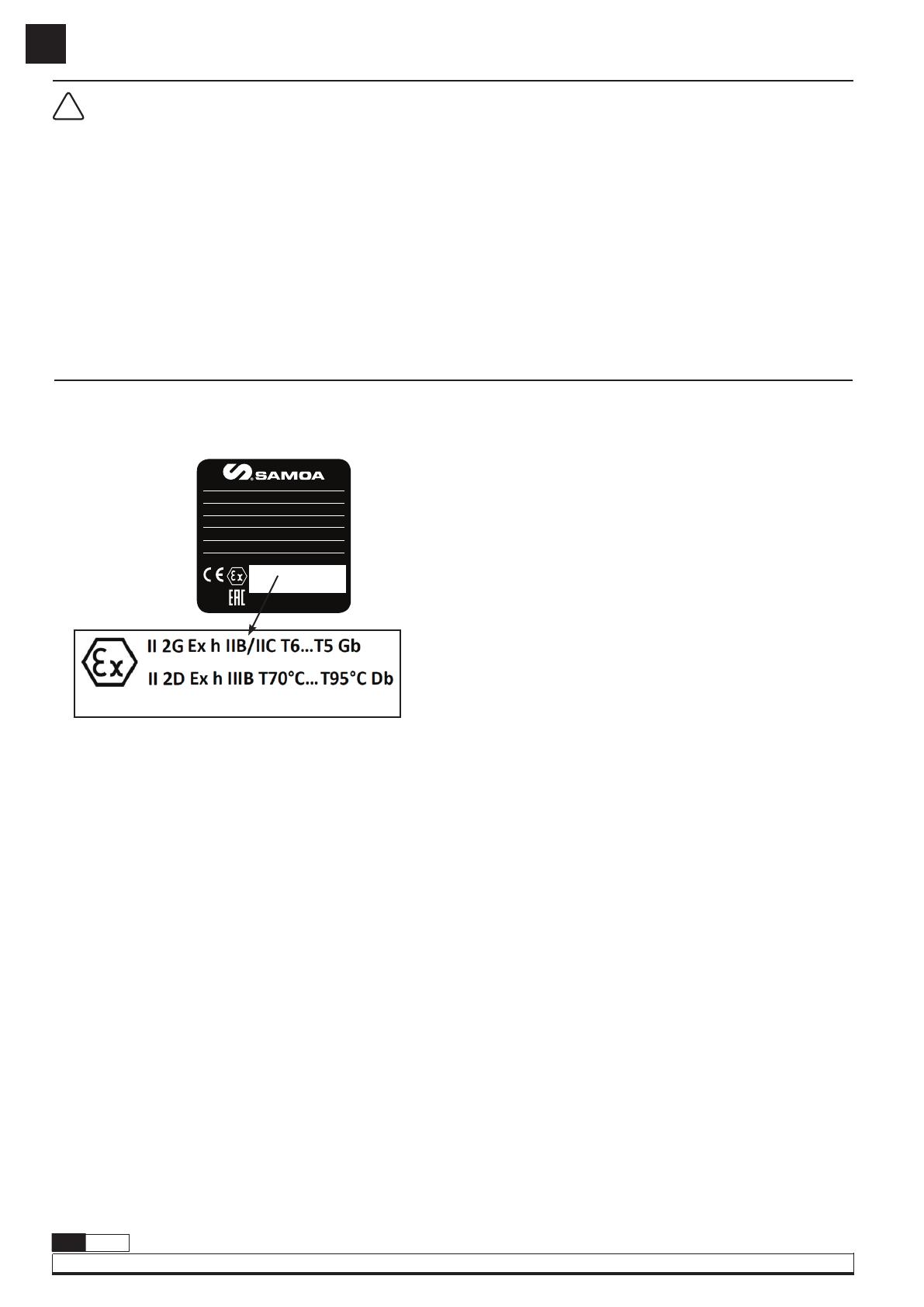
МАРКИРОВКА ATEX
На поверхности помпы, к которой прилагается данное руководство, вы
должны найти этикетку, подобную той, что показана на приложенном
рисунке ниже. Указанная этикетка содержит следующую информацию (не
используйте насос в атмосфере ATEX, если на ней нет указанной этикетки).
Ex: Указывает, что этот насос можно использовать в потенциально
взрывоопасной атмосфере.
II: Указывает группу устройств, которая соответствует насосу. В этом
случае, принадлежность к группе II указывает на то, что это
оборудование можно использовать в месте, где существует опасность
образования ATEX. Это относится к группе для промышленного
применения на поверхности.
2: Указывает категорию внутри группы, соответствующую
оборудованию. Категория оборудования 2 указывает на Высокий
Уровень Защиты (использование оборудования в зонах 1 и 2 для Газа
и в зонах 21 и 22 для Пыли).
Оборудование категории 2 в группе II – это оборудование,
предназначенное для работы в пределах рабочих параметров,
установленных изготовителем, и обеспечивающее высокий уровень
защиты при использовании по назначению в местах, где возможно
образование взрывоопасных сред из-за смесей воздуха с газами,
паров, туманов и, если указано, воздушно-пылевыми смесями.
Категория 2 в Группе II — это оборудование, предназначенное для
работы в пределах рабочих параметров, установленных производителем,
и обеспечивающее высокий уровень защиты для его использования по
назначению в местах, где взрывоопасные среды из-за смесей воздуха
с газами, парами, туманами и где воздух/пыль возможны смеси.
Взрывозащита обеспечивает достаточный уровень безопасности даже
в случае неисправностей или работы в опасных условиях, которые
обычно необходимо учитывать..
G: Тип атмосферы Газ. Указывает, что насос можно использовать в
потенциально взрывоопасной среде из-за газа, пара или тумана.
D: Тип атмосферы Пыль. Указывает, что насос можно использовать
в потенциально взрывоопасной атмосфере из-за наличия пыли.
h:
Указывает на то, что насос имеет защиту конструкции, так как
это неэлектрическое оборудование. Дополнительный режим
защиты не применяется.
IIB/IIC: Указывает группу взрывоопасности газов, которые могут
образовывать взрывоопасную среду, для которой подходит данный
насос (в данной инструкции отмечены условия, необходимые для
использования насоса с каждой группой взрывоопасности). В
частности, эти группы относятся к горючим газам (этилен) и легко
воспламеняющимся газам (водород) соответственно.
IIIB: Указывает группу взрывоопасной пыли, которая может
образовывать взрывоопасную атмосферу, для которой подходит
насос. В частности, эта группа относится к непроводящей пыли.
T6…T5 (Газ) / T70°C…T95°C (Пыль): Это указывает на ограничение,
наложенное SAMOA Industrial на использование насоса с газами групп
IIB и IIC, а также с порошками группы IIIB. Температурное ограничение,
установленное SAMOA Industrial, составляет 95°C. Так как в
нормальных условиях насос никогда не достиг бы этой температуры,
то имеется в виду максимальная температура жидкости, которую
может перекачивать оборудование без риска воспламенения
указанных газов и пыли. В других случаях может быть отмечена
максимальная температура поверхности любой части оборудования,
которая может подвергаться воздействию потенциально
взрывоопасной среды в самых неблагоприятных условиях. В случае
атмосферы, создаваемой смесью воздуха (G) и пыли (D), обратите
внимание, что максимальная температура поверхности любой части
оборудования в насосе будет зависеть от температуры
перекачиваемой жидкости как пока она не превышает 30°C.
Gb: Уровень Защиты Оборудования 1 для газовой атмосферы
(атмосфера иногда присутствует при нормальном использовании
оборудования). Указывает на то, что оборудование имеет высокий
уровень защиты (уровень защиты, присвоенный оборудованию в
соответствии с риском стать источником воспламенения), даже если
оно может быть или не быть источником воспламенения в нормальных
условиях эксплуатации или во время предсказуемых поломок.
Db: Уровень Защиты Оборудования 1 для запыленной атмосферы
(атмосфера иногда присутствует при нормальном использовании
оборудования). Указывает на то, что оборудование имеет высокий
уровень защиты (уровень защиты, присвоенный оборудованию в
соответствии с риском стать источником воспламенения), даже если
оно может быть или не быть источником воспламенения в нормальных
условиях эксплуатации или во время прогнозируемых поломок.
LOM YY.###-#: Указывает регистрационный номер (наименование
поставщика выдавшего сертификат и его номер) технической
документации, которая была передана на хранение в
нотифицированный орган (см. декларацию о соответствии).
X: Буква «X», расположенная после номера сертификата,
указывает на особые условия безопасного использования,
которые доводятся до сведения конечного пользователя в данной
инструкции по эксплуатации.
LOM 20.115M-CX
II 2G Ex h IIB/IIC T6...T5 Gb
II 2D Ex h IIIB T70ºC...T95ºC Db
LOM 20.115M-CX
0163
CODE:
MAXIMUM AIR PRESSURE:
MAXIMUM FLUID PRESSURE:
FLUID IN / OUT:
MFG. DATE: SERIAL No.:
MODEL:
www.samoaindustrial.com
MADE IN SPAIN • PATENTED


