
2021_09_06-14:00
1
R. 09/21 855 835
SAMOA Industrial, S.A. · Pol. Ind. Porceyo, I-14 · Camino del Fontán, 831 · 33392 - Gijón - Spain · Tel.: +34 985 381 488 · www.samoaindustrial.com
Parts and technical service guide
Guía de servicio técnico y recambio
Guide d’instructions et pièces de rechange
Service- und Ersatzteilhandbuch
Part No. / Cód. / Réf. / Art. Nr.
556XXX
DC20XXXXXXXXX
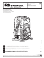
1/4" DOUBLE DIAPHRAGM PUMP DC20, 20 l/min (5,28 US gal/min) 1
BOMBA DE DOBLE MEMBRANA 1/4" DC20, 20 l/min (5,28 US gal/min) 12
POMPE A MEMBRANES 1/4” DC20, 20 l/min (5,28 US gal/min) 20
DOPPELMEMBRANPUMPE 1/4” DC20, 20 l/min (5,28 US gal/min) 28
EN
ES
FR
DE

2855 835 R. 09/21
SAMOA Industrial, S.A. · Pol. Ind. Porceyo, I-14 · Camino del Fontán, 831 · 33392 - Gijón - Spain · Tel.: +34 985 381 488 · www.samoaindustrial.com
2021_09_06-14:00
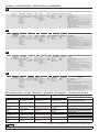
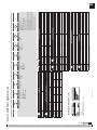
CODING / CODIFICACIÓN / CODIFICATION / KODIERUNG
DC20 X X X X X X X X X
AIR VALVE BODY PUMP PUSH ROD SEALS SEATS BALLS DIAPHRAGMS CONECTIONS OPTIONS
P Polypropylene P Polypropylene
B Conductive PP
C POM
D Conductive
POM
W PVDF
K Conductive
PVDF
S Stainless steel
Y Hastelloy® C
V FKM
E EPDM
T PTFE
P Polypropylene
C POM
W PVDF
M Santoprene®
H Hytrel®
T PTFE
C POM
H Hytrel®
T PTFE
M Santoprene®
B BSP
N NPT
A Standard pump
C Diaphragm leak detector
D Cycle sensor
E Externally controlled with solenoid valve (not incl.)
F Nose muffler included
G Externally controlled with solenoid valve (not included)
and inductive end of stroke sensors NPN (included)
I Externally controlled with solenoid valve (not
included) and inductive end of stroke sensors ATEX-
Namur (included)
U Pump suitable for UV fluids
DC20 X X X X X X X X X
DISTRIBUIDOR
DE AIRE CUERPO AXIS JUNTAS ASIENTOS BOLAS DIAFRAGMAS CONEXIONES OPCIONES
P Polipropileno P Polipropileno
B PP conductivo
C POM
D POM
conductivo
W PVDF
K PVDF
conductivo
S Acero
inoxidable
Y Hastelloy® C
V FKM
E EPDM
T PTFE
P Polipropileno
C POM
W PVDF
M Santoprene®
H Hytrel®
T PTFE
C POM
H Hytrel®
T PTFE
M Santoprene®
B BSP
N NPT
A Bomba estándar
C Detector de fugas en el diafragma
D Sensor de ciclo
E Controlado externamente con electroválvula (no incl.)
F Silenciador de nariz incluido
G Controlado externamente con electroválvula (no incl.) y
sensores inductivos de fin de carrera NPN (incluidos)
I Controlado externamente con electroválvula (no incl.)
y sensores inductivos de fin de carrera ATEX-Namur
(incluidos)
U Bomba adecuada para fluidos UV
DC20 X X X X X X X X X
DISTRIBUTEUR
D’AIR CORPS POMPE EJE JOINTS SIÈGES BALLES DIAPHRAGMES CONNEXIONS OPTIONS
P Polypropylène P Polypropylène
B PP conductive
C POM
D POM
conductive
W PVDF
K PVDF
conductive
S Acier
inoxydable
Y Hastelloy® C
V FKM
E EPDM
T PTFE
P Polypropylène
C POM
W PVDF
M Santoprene®
H Hytrel®
T PTFE
C POM
H Hytrel®
T PTFE
M Santoprene®
B BSP
N NPT
A Pompe standard
C Détecteur de fuites à diaphragme
D Capteur de cycle
E Commande externe avec électrovanne (non incluse)
F Silencieux de nez inclus
G Commande externe avec électrovanne (non incluse) et
capteurs inductifs de fin de course NPN (inclus)
I Commande externe avec électrovanne (non incluse)
et capteurs inductifs de fin de course ATEX-Namur
(inclus)
U Pompe adaptée aux fluides UV
DC20 X X X X X X X X X
LUFTVENTIL KÖRPER SCHUBSTANGE
DICHTUNG
SITZE BÄLLE MEMBRAN VERBINDUNGEN OPTIONEN
P Polypropylen P Polypropylen
B Leitfähiges PP
C POM
D Leitfähiges
POM
W PVDF
K Leitfähiges
PVDF
S Rostfreier Stahl
Y Hastelloy® C
V FKM
E EPDM
T PTFE
P Polypropylen
C POM
W PVDF
M Santoprene®
H Hytrel®
T PTFE
C POM
H Hytrel®
T PTFE
M Santoprene®
B BSP
N NPT
A Standard-Pumpe
C Membran-Lecksucher
D Zyklus-Sensor
E Externe Steuerung mit Magnetventil (nicht enthalten)
F Inklusive Nasenschalldämpfer
G Externe Steuerung mit Magnetventil (nicht enthalten)
und induktive Endlagensensoren NPN (inkl.)
I Externe Steuerung mit Magnetventil (nicht enthalten)
und induktive Endlagensensoren ATEX-Namur (inkl.)
U Pumpe geeignet für UV-Flüssigkeiten
TECHNICAL DATA / DATOS TÉCNICOS / DONNÉES TECHNIQUES / TECHNISCHE DATEN
DC20
RATIO RATIO RATIO ÜBERSETZUNGSVERHÄLTNIS 1:1
MAXIMUM FREE
FLOW
MÁXIMO CAUDAL
SALIDA LIBRE
DÉBIT MAXIMAL
SORTIE LIBRE
FÖRDERLEISTUNG
BEI FREIEM AUSLAUF 5,28 Us gal/min (20 l/min)
AIR PRESSURE
OPERATING RANGE RANGO DE PRESIÓN PLAGE DE PRESSION LUFTDRUCKEINSATZBEREICH 22 to 115 psi (1,5 a 7 bar)
SOLID IN SUSPENSION
MAX SIZE
MAX. TAMAÑO DE
PARTÍCULAS EN SUSPENSIÓN
TAILLE MAXIMALE DES
PARTICULES EN SUSPENSION
MAXIMALE
PARTIKELGRÖSSE 3/32" (2 mm)
MAXIMUM SUCTION
HEAD
ALTURA MÁXIMA
DE SUCCIÓN
HAUTEUR D’ASPIRATION
MAXIMALE
MAXIMALE
ANSAUGHÖHE
6 1/2" ft (2 m) dry / seco / sec / trocken
23 ft (7 m) wet / húmedo / humide / nass
WEIGHT PESO POIDS GEWICHT 2,65 lb (1,2 kg)
FLUID INLET/OUTLET
CONNECTIONS
ENTRADA DE FLUIDO/
CONEXIONES DE SALIDA
ENTRÉE DU FLUIDE/
CONNEXIONS DE SORTIE
FLUIDEINLASS (EINZELEIN-
LASS) /FLUIDAUSLASS
1/4" BSP (F) or NPT (F)
3/4" NPT (M)
AIR INLET ENTRADA DE AIRE ENTRÉE D’AIR ANSCHLUSS DRUCKSEITE 3/8" NPSM (F)
TEMPERATURE
RANGE
RANGO DE TEMPERATURAS
DE TRABAJO
PLAGE DE TEMPÉRATURE
DE TRAVAIL TEMPERATURBEREICH 32 -158 ºF (0 - 70 ºC)
(oz, ft, gal/min) all in EEUU units. / (oz, ft, gal/min) todo en unidades EEUU /
(oz, ft, gal/min) todo en unidades EEUU / (oz, ft, gal/min) todo en unidades EEUU
EN
ES
FR
DE

2021_09_06-14:00
3
R. 09/21 855 835
SAMOA Industrial, S.A. · Pol. Ind. Porceyo, I-14 · Camino del Fontán, 831 · 33392 - Gijón - Spain · Tel.: +34 985 381 488 · www.samoaindustrial.com
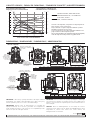
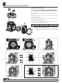
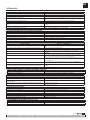
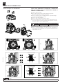
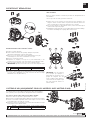
CAPACITY CURVES / CURVAS DE CAPACIDAD / COURBES DE CAPACITÉ / KAPAZITÄTSKURVEN
DIMENSIONS / DIMENSIONES / DIMENSIONS / ABMESSUNGEN
FLUID INLET
ENTRADA FLUIDO
ENTRÉE DE FLUIDE
FLÜSSIGKEITSEINLAUF
1/4” BSP/NPT (F)
3/4” NPT (M)
FLUID OUTLET
SALIDA FLUIDO
SORTIE DE FLUIDE
FLUIDAUSGANG
1/4” BSP/NPT (F)
3/4” NPT (M)
AIR INLET / ENTRADA AIRE
ENTRÉE D’AIR / LUFTEINLASS
(3/8” NPSM)
AIR OULET / SALIDA AIRE
SORTIE D’AIR / LUFTAUSGANG
A
A2A1
F1
F
E
D
C
B
C
FLUID INLET
ENTRADA FLUIDO
ENTRÉE DE FLUIDE
FLÜSSIGKEITSEINLAUF
1/4” BSP/NPT (F)
3/4” NPT (M)
FLUID OUTLET
SALIDA FLUIDO
SORTIE DE FLUIDE
FLUIDAUSGANG
1/4” BSP/NPT (F)
3/4” NPT (M)
AIR INLET
ENTRADA AIRE
ENTRÉE D’AIR
LUFTEINLASS
(3/8” NPSM)
AIR OULET / SALIDA AIRE
SORTIE D’AIR / LUFTAUSGANG
A
A2
A1
F1
F
E
D
C
B
C
A A1 A2 B C D E F F1 G G1 H
mm 142 67 75 142 173 142 29 108 79 96 86 9
in. (“) 5.59” 2.64” 2.95” 5.59” 6.81" 5.59” 1.14” 4.25” 3.11” 3.78” 3.38” 0.35”
A A1 A2 B C D E F F1
mm 140 8 132 142 173 142 29 108 79
5.51” 0.31” 5.2” 5.59” 6.81" 5.59” 1.14” 4.25” 3.11”
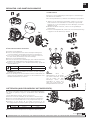
IMPORTANT: When doing a pump maintenance that implies manifold
disassembling and pump is fitted with PTFE o-rings (white colour), they
must be replaced by new ones in order to avoid fluid leakages.
IMPORTANTE: Cuando realice un mantenimiento en la bomba que
implique desmontaje de los colectores y la bomba esté configurada con
juntas de PTFE (color blanco), estas tienen que ser reemplazadas por unas
nuevas con objeto de evitar fugas de fluido.
IMPORTANT: Lors de l’entretien de la pompe qui implique le démontage
des collecteurs et si la pompe est configurée avec des joints en PTFE (couleur
blanche), ceux-ci doivent être remplacés par des joints neufs afin d’éviter les
fuites de liquide.
WICHTIG: Wenn bei Wartungsarbeiten an der Pumpe die Verteiler
demontiert werden müssen und die Pumpe mit PTFE-Dichtungen (weiß)
ausgestattet ist, müssen diese durch neue ersetzt werden, um
Flüssigkeitsverluste zu vermeiden.
G1
G
H
Tested at room temperature, using water. Flooded pump with 3.5
inches (80 mm), positive suction head.
Ensayo realizado con agua a temperatura ambiente y bomba
inundada en 80 mm de succión positiva.
L’essai a été effectué avec de l’eau à température ambiante et une
pompe inondée à 80 mm d’aspiration positive.
Der Test wurde mit Wasser bei Umgebungstemperatur durchgeführt,
wobei die Pumpe mit 80 mm positivem Sog geflutet wurde.
AIR CONSUMPTION / CONSUMO DE AIRE
CONSOMMATION D’AIR / LUFTVERBRAUCH
FLUID PRESSURE / PRESIÓN DE FLUIDO
PRESSION DU FLUIDE / FLÜSSIGKEITSDRUCK
bar psi
114.5
2 29
3 43.5
4 58
5 72.5
6 87
7
8
100
126
0 0
Nl/min SCFM
200
250
300
150
100
50
0
7.04
8.80
5.19
10.52
3.53
1.76
0
FLOW / CAUDAL / DÉBIT / DURCHFLUSSMENGE
0 1.32 2.64 3.96 5.28
0 5 10 15 20
US gal/min
l/min
4 bar - 60 psi
2 bar - 30 psi
6 bar - 90 psi
8 bar - 120 psi
8 bar - 120 psi
6 bar - 90 psi
4 bar - 60 psi
2 bar - 30 psi
AIR CONSUMPTION / CONSUMO DE AIRE
CONSOMMATION D’AIR / LUFTVERBRAUCH
PUMP FLOW / CAUDAL
DÉBIT / DURCHFLUSSMENGE

4855 835 R. 09/21
SAMOA Industrial, S.A. · Pol. Ind. Porceyo, I-14 · Camino del Fontán, 831 · 33392 - Gijón - Spain · Tel.: +34 985 381 488 · www.samoaindustrial.com
2021_09_06-14:00
EN
• This equipment is for professional use only.
• Do not degrade the integrity of the equipment. Use only original
replacement components from Samoa Industrial, S.A.
• Fluids not suitable for the pump can cause damage to the pump unit and
involve risk of serious personal injury.
• Always consult Samoa Industrial, S.A. if you have any questions about the
compatibility within the fluids and the pump materials, including
elastomers.
• Install and use the pump according to all local and national regulations
and abide all health and safety laws or legislation.
• The pump can produce fluid pressures equal to the air supply pressure. Do
not exceed the maximum allowable pressure of 115 psi (7 bar) air supply.
The total hydraulic pressure (differential pressure + system) should never
exceed 115 psi (7 bar).
• Never use a pump that leaks, that is damaged, that is corroded or
otherwise it may lack the capacity to contain the fluid.
• Frequently check that the bolts on the diaphragm cover of the pump are
torqued correctly.
• Do not use a model with aluminium wetted surfaces to pump fluids for
human consumption, there is a possibility of trace contamination of lead.
• Danger of explosion if used 1,1,1-trichloroethane, methylene chloride or
other halogenated hydrocarbon solvents with aluminium wetted materials.
It could cause serious injury and property damage.
• Inside the pump, diaphragms separate the fluid that is being pumped
from the air supply. If a diaphragm breaks, the fluid can leak out of the air
exhaust and contaminate the environment.
• When handling hazardous fluids, always route the air exhaust into a
suitable container and locate it in a safe place.
• When the fluid source level is situated higher than the pump, (flooded
suction), the outlet tank must be at a higher level than the product to
prevent spills.
• For pumps handling hazardous fluids that are a danger to humans or to
the environment, install a suitable container surrounding the pump to
prevent any leaks or spills.
• Ensure that the operators of this equipment are trained on the operation
and limitations. Use safety equipment as safety goggles or other
equipment required.
WARNING: CAREFULLY READ THE INSTRUCTIONS AND WARNINGS BEFORE OPERATING THE EQUIPMENT!
WARNINGS AND CAUTIONS
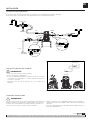
Air operated double diaphragm pumps are air-powered, reciprocating
positive displacement pumps with two pumping chambers. Two diaphragms,
centrally located in the chambers, separate the compressed air (dry side)
from the fluid being pumped (wet side). A shaft transmits the reciprocating
motion of one diaphragm to the other. A directional valve alternatively
distributes the air from one chamber to the other; thus a reciprocating
movement of the diaphragms is created. With each stroke, fluid is discharged
by one of the diaphragms whilst the opposite diaphragm sucks new fluid into
the expanding chamber. Check valves, two on the discharge side and two on
the suction side, control and direct the fluid flow.
DESCRIPTION
• Remove the pump from its package and install it on the chosen location.
• Try to minimize the suction head. Install the pump as close as possible to
the fluid being pumped.
• Remember to have enough space around the pump to perform
maintenance tasks.
• Keep in mind to connect the inlet and outlet of the pump correctly.
• In case of diaphragm pump failure, the air exhaust will expel the product
being pumped.
• When the pump is installed in a place where a spill of fluid can cause an
environmental impact, the exhaust should be directed to a place.where
this spill could be contained.
• When installing the pump in its place, use brackets to
secure its base.
• Fasten all bolts with the torques contained in this manual.
NOTE: Use a pressure regulator with built-in
filter inlet.
MATERIAL TEMPERATURE RANGE
PTFE 5 ºC - 105 ºC /41 ºF - 221 ºF
NBR 10 ºC - 80 ºC /50 ºF - 176 ºF
Acetal 10 ºC - 90 ºC /50 ºF - 194 ºF
Hytrel®10 ºC - 90 ºC /50 ºF - 194 ºF
Santoprene®-29 ºC - 135 ºC /-20 ºF - 275 ºF
Viton®-10 ºC - 120 ºC /-4 ºF - 248 ºF
Polypropylene 10 ºC - 80 ºC /50 ºF - 176 ºF
WARNING: This symbol aware that there is a danger of serious bodily injury or death if you ignore the warning described.
CAUTION: This symbol aware that there is a danger of personal injury or property damage if you ignore the caution described.
In this document you will find warnings and cautions for installation, use and maintenance of the pumps.
Here’s the meaning of symbols you may find in this document and general warnings that you should keep in mind.
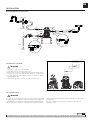
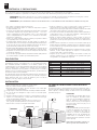
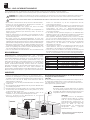
INSTALLATION
I
AIR
EXHAUST
AR
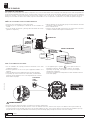
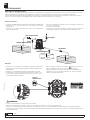
DC PUMPS ARE VERY EASILY CONFIGURED AND EASY TO INSTALL.
FLOODED:
The pumping system was designed with positive pressure at the inlet. This is
the best possible installation when you need to evacuate the liquid from the
drum or tank, or when working with viscous fluids.
Not recommended for hazardous fluids.
SELF-PRIMING:
Pump is designed to generate vacuum. It is
possible to evacuate all the air from a hose or
pipe without damaging the pump. Maximum
suction height is 6 1/2" (2 m), with the
suction hose empty and up to 23“ (7 m) with
the hose primed. (See page 1 for corresponds
suction lift).
SUBMERGED:
All pumps can be immersed in fluids. It is
important to verify that all components that
are in contact with the fluid are chemically
compatible. In this case, air exhaust and fluid
must be carried by hoses (optional air
connection).
I
AR
FLOODED
SELF-PRIMING
SUBMERGED

5
R. 09/21 855 835
SAMOA Industrial, S.A. · Pol. Ind. Porceyo, I-14 · Camino del Fontán, 831 · 33392 - Gijón - Spain · Tel.: +34 985 381 488 · www.samoaindustrial.com
EN
2021_09_06-14:00
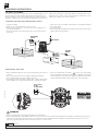
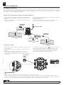
• Optional kit is required for remote exhaust.
• Unscrew the 4 bolts and remove the air cap.
• Connect a hose to the new exhaust port and install the muffler at the
end of the hose. Use a hose with the same diameter as the exhaust port
3/8" NPT. (If the hose is more than 5 feet (1.5 m), consult your dealer or
Samoa Industrial, S.A.).
• Have a moat, a protective housing, etc. at the end of the hose.
WARNING
To ensure that the air supply is sufficient to meet the demand of the pump,
the diameter of the pipe must be equal to the diameter of the supply port
of the pump. Choose auxiliary air treatment equipment and fittings with
sufficient airflow to exceed the air consumption of the pump. In addition,
peripheral air treatment equipment must be installed as close as possible to
the pump unit.
The use of a coupler to connect the hoses aids future operation and
maintenance tasks.
INSTALLATION
AIR EXHAUST DISPOSAL
WARNING
AIR CONNECTION
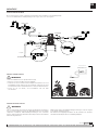
RECOMMENDED INSTALLATION
OUTLET
FLUID
INLET
SUCTION
DRAINING
VALVE
DISCHARGE
DRAINING
VALVE
INLET
MAX. 7 bar
OPTION
OPTION
OPTION
3/8”
3/8”
1/4”
1/4”
>=1/4”
>=1/4”
3/8" NPT
REMOTE EXHAUST

6855 835 R. 09/21
SAMOA Industrial, S.A. · Pol. Ind. Porceyo, I-14 · Camino del Fontán, 831 · 33392 - Gijón - Spain · Tel.: +34 985 381 488 · www.samoaindustrial.com
2021_09_06-14:00
EN
THIS PUMP IS SELF-PRIMING.
To prime it the first time, you must connect the air pump supply to a low
pressure using the pressure regulators while keeping the outlet valve open.
When fluid begins to flow from the pump outlet, the pump is primed. For
regulation of fluid pressure, the unit must be supplied with an air pressure
between 14 and 100 psi (1 and 7 bar). Adjust the discharge valve on the
discharge side to control flow. For the performance characteristics of the
pump see the capacity curve shown on page 2.
• Stop the air supply.
• Make sure for your safety that the air valve is closed.
• Turn off the air compressor, or close the valve on the air supply side of
the auxiliary equipment.
• Close the discharge valve and the suction valve. Open inlet and outlet
drain valves.
• Connect grounding wires to the pump, piping and all other equipment too.
• When the pump operates ungrounded or with an incorrect connection, friction between parts and abrasion caused by some fluids that flow inside the
pump, can generate static electricity. Moreover, according to the type of fluid pump and the installation environment (such as gases in the air or the
type of the surrounding facilities) static electricity can cause fire or electric shock.
• When installing the pump, be sure to perform grounding in the specified
location.
• Also connect ground wires for the auxiliary equipment and piping.
• Use a grounding cable of at least 12 gauge (2.0 mm2).
• If the pump you have purchased is valid for Atex, a specific Atex manual
will accompany this one. Read this manual before operating the pump.
OPERATING INSTRUCTIONS
STOPPING THE PUMP FOR MAINTENANCE TANKS
• Open the air valve of the pump, running bring on the pump and flushing
the remaining fluid.
• Close the air valve.
• After ensuring that the pump was turned off and the pressure was released,
pump is ready for its maintenance.
GROUNDING THE PUMP
WARNING
DISCHARGE
VALVE
AIR VALVE
SUCTION
VALVE
INLET
DRAIN
VALVE
OUTLET
DRAIN
VALVE
THE POSITION
OF THE
GROUND WIRE
• If the unit is marked with the symbol,
it can be used in potentially
explosive atmospheres. Below this symbol, in the nameplate of the pump,
are indicated the areas for which the equipment is approved. You will also
find the maximum allowable surface temperature in the same plate.

7
R. 09/21 855 835
SAMOA Industrial, S.A. · Pol. Ind. Porceyo, I-14 · Camino del Fontán, 831 · 33392 - Gijón - Spain · Tel.: +34 985 381 488 · www.samoaindustrial.com
EN
2021_09_06-14:00
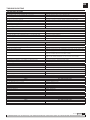
TROUBLESHOOTING
THE PUMP DOES NOT WORK
Cause Recommended measure
The discharge valve on the discharge side is not open. Open the discharge valve on the discharge side.
No air supply. Turn on the compressor and open the air valve and air regulator.
The air supply pressure is low. Check the compressor and the configuration of the air line.
Air leaks in connecting elements. Check the connection elements and the tightening of the screws.
The air pipes or ancillary equipment is clogged with mud. Check and clean the air line.
The exhaust port (muffler) of the pump is clogged with mud. Check and clean the exhaust port and muffler.
The fluid pipe is clogged with mud. Check and clean the fluid line.
Pump is clogged with mud. Remove, inspect and clean the pump body.
THE PUMP RUNS BUT NO FLUID COMES OUT
Cause Recommended measure
The valve on the suction side is not open. Open the valve on the suction side.
Too much suction or discharge height. Confirm the configuration of the pipe and reduce the height of the same.
Fluid pipe discharge side (including the filter) is clogged with mud. Check and clean the fluid line.
Pump is clogged with mud. Dismantle the pump, check and clean.
The ball and ball seat is worn or damaged. Inspect and replace parts.
THE FLOW IS DECREASING
Cause Recommended measure
The air supply pressure is low. Check the compressor and the configuration of the air line.
The air line or peripheral equipment clogged with mud. Check and clean the air line.
Valve discharge side drive will not open normally. Adjust the discharge valve discharge side.
The air mixes with the fluid. Replenish fluid and check the configuration of the pipe on the suction side.
Cavitation occurs. Adjust air supply pressure and discharge pressure and reduce the suction.
Vibrations. Adjust air supply pressure and discharge pressure. Reduce the flow of the
inlet valve to adjust pressure and volume of fluid.
Ice formation in the air exhaust. Remove ice from the air bypass valve and check and clean the air filter. Use
a pipe in the exhaust air that the ice does not form in the muffler.
The fluid line (including the filter) plugged with mud. Check and clean the fluid pipe and strainer.
The exhaust port (muffler) of the pump is clogged with mud. Check and clean the exhaust port and muffler.
Pump is clogged with mud. Remove, inspect and clean the pump body.
LEAKAGE OF FLUID THROUGH THE HOLLOW EXHAUST (SILENCER)
Cause Recommended measure
The diaphragm is damaged. Remove and inspect the pump and replace the diaphragm.
IRREGULAR NOISE
Cause Recommended measure
The air supply pressure is too high. Adjust air supply pressure.
The pump is clogged with sludge particles larger than the diameter allowed. Remove, check and clean the pump body.
IRREGULAR VIBRATION
Cause Recommended measure
The elements of connection and the support of the pump are loose. Review each element of connection and tighten the screws.
The air supply pressure is too high. Adjust air supply pressure.
The range and ball valve vibrates. Adjust air supply pressure and exhaust pressure.
POWERED AIR LEAK PRESSURE OF 3 TO 8 BAR
Cause Recommended measure
Wear directional valve. Replace directional valve components.
NO START-UP AND IS LEAKING AIR WITHOUT CYCLES
Cause Recommended measure
Stiff air sensors. Change air sensor.
Wear directional valve. Replace.
IN FLUID WITH AIR BUBBLES
Cause Recommended measure
Diaphragm damaged. Replace diaphragm.
Suction hose loose or broken. Tighten or replace.

8855 835 R. 09/21
SAMOA Industrial, S.A. · Pol. Ind. Porceyo, I-14 · Camino del Fontán, 831 · 33392 - Gijón - Spain · Tel.: +34 985 381 488 · www.samoaindustrial.com
2021_09_06-14:00
EN
1
24
7
5
8
6
3
4_4 4_3
4_2
4_1
1_31
1_32
1_33
1_34
1_30
1_35
1_36
7_3
7_1
7_2
1_37
1_38 7_2
7_1
7_4
5_1
5_2
5_1
5_1
6_1
6_1
2_1
2_4
2_4
2_3
1_7
1_2
1_3
1_4 1_5
1_6
1_1
1_9
1_8
1_5
1
6
SENSOR 5
6
5
4
7
BALLS
BALLS
SORT SEATS
SORT SEATS
HYTREL SANTROPRENE
7
PTFE-NBR-EPDM-FKM
5
HEARD SEATS + SEALS
PUSHING ROD/BUSHING/SEALS
1
SPOOL AIR
VALVE
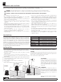
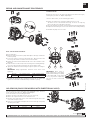
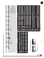
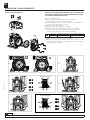
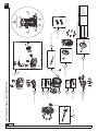
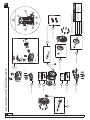
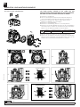
PLASTIC PUMP PARTS DRAWING DC20
REGULAR MAINTENANCE SCREWS AND TOOLS
SCREW TYPE REQUIRED TOOL
DIRECTIONAL VALVE
Flanged hex head
screw Socket wrench Metric:
8 mm Standard: 5/16”
FLUID MANIFOLDS
(Valve, seat and seals)
DIAPHRAGM COVERS
(Diaphragm and central
pushing rod)
*Further maintenance (Air Sensors and Spool valve)
will require a T20 Torx screwdriver
2
OUTLET MANIFOLD
2
BODY
2
INLET MANIFOLD
KIT
KIT
KIT
KIT
KIT
KIT
KIT
KIT
KIT
KIT
CAUTION
(TIGHTENING SECUENCE)

9
R. 09/21 855 835
SAMOA Industrial, S.A. · Pol. Ind. Porceyo, I-14 · Camino del Fontán, 831 · 33392 - Gijón - Spain · Tel.: +34 985 381 488 · www.samoaindustrial.com
EN
2021_09_06-14:00
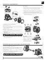
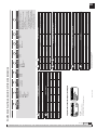
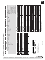
DC20XXXXXXXXXX
1 2 3 4 5 6 7 8 9
PLASTIC PUMP PARTS DRAWING DC20
TECHNICAL CHARACTERISTICS LABEL
AIR VALVE BODY PUMP PUSH ROD SEALS SEATS BALLS DIAPHRAGMS CONECTIONS OPTIONS
P Polypropylene P Polypropylene
B Conductive PP
C POM
D Conductive POM
W PVDF
K Conductive PVDF
S Stainless steel
Y Hastelloy® C
V FKM
E EPDM
T PTFE
P Polypropylene
C POM
W PVDF
M Santoprene®
H Hytrel®
T PTFE
C POM
H Hytrel®
T PTFE
M Santoprene®
B BSP
N NPT
A Standard pump
C Diaphragm leak detector
D Cycle sensor
E Externally controlled with
solenoid valve (not included)
F Nose muffler included
G Externally controlled with solenoid valve
(not included) and inductive end of stroke
sensors NPN (included)
I Externally controlled with solenoid valve
(not included) and inductive end of stroke
sensors ATEX-Namur (included)
U BPump suitable for UV fluids
AIR VALVE
AIR VALVE AIR SENSORS
POS 1_1 a 1_9 POS 1_30 a 1_38
P558623 558624
1
CENTRAL BODY AND MANIFLOD
CENTRAL BODY INLET MANIFLOD OUTLET MANIFLOD
POS 2_1 POS 2_2 POS 2_3
BSP (threads) NPT (threads) BSP (threads) NPT (threads)
P894692 894697 894697.300 894698 894698.300
B894693 894699 894699.300 894700 894700.300
CN/A N/A N/A N/A N/A
D894694 894701 894701.300 894702 894702.300
W755413 894703 894703.300 894704 894704.300
K894696 894705 894705.300 894706 894706.300
2
PUSH ROD REPAIR KIT
PUSH ROD SEALS CÓD. KIT NUMERICAL CODING 556XXX
ATEX PUMP NO ATEX PUMP
S V 558600 558605 556115
S E 558601 558606
S T 558602 558607
Y V 558603 558608
Y T 558604 558609
3 4
SEATS VALVE REPAIR KIT
SEATS SEALS CÓD. KIT NUMERICAL CODING 556XXXXX
P V 558610 556115
P E 558611
P T 558612
C V 558613
C E 558614
C T 558615
W T 558616
H _ 558617
M _ 558618
5 4
BALLS VALVE REPAIR KIT
CÓD. KIT NUMERICAL CODING 556XXX
C558321
T558319 556115
6
DIAPHRAGMS
CÓD. KIT NUMERICAL CODING 556XXX
(1) 558619
T(2) 558620
M558621 556115
H558622
7
(1) For pump fitted with stainless steel central pushing rod.
(2) For pump fitted with hastelloy® C central pushing rod.
MODEL:
556XXX (numerical coding)
DC20XXXXXXXXX (alphanumeric coding)

10 855 835 R. 09/21
SAMOA Industrial, S.A. · Pol. Ind. Porceyo, I-14 · Camino del Fontán, 831 · 33392 - Gijón - Spain · Tel.: +34 985 381 488 · www.samoaindustrial.com
2021_09_06-14:00
EN
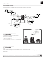
Before any intervention: DISCONNECT AIR SUPPLY OF THE PUMP.
IT IS NOT NECESSARY TO REMOVE THE PUMP FROM THE FLUID LINE.
1. Close fluid valves.
2. Drain the fluid inside the pump. Anticipate a drainage of fluid from inside
the pump.
3. Remove the directional valve while being careful not to damage the seals
shown in the figure.
4. Remove the diaphragm cap.
NOTE: To tighten these screws you must use a torque wrench calibrated
to (see torque table in this page).
5. Remove the cover by gently pulling back.
6. Remove the used diaphragm and place the new one in the proper position.
Assemble cover according to the following table:
REPAIR AND MAINTENANCE PROCEDURES
DIAPHRAGM REPLACEMENT
1
24
7
5
8
6
3
1
24
7
5
8
6
3
7. Same procedure in other diaphragm.
8. Assemble the directional valve checking all O-rings seals are placed
and tighten the screws with a maximum torque of 44 lbf.in (5 N.m).
Tightening secuence
Tightening secuence
PP body PP conductive body POM conductive body
5 N·m 4.2 N·m 5 N·m
A B
C D
E F

11
R. 09/21 855 835
SAMOA Industrial, S.A. · Pol. Ind. Porceyo, I-14 · Camino del Fontán, 831 · 33392 - Gijón - Spain · Tel.: +34 985 381 488 · www.samoaindustrial.com
EN
2021_09_06-14:00
Remove the side cover on the right of the fluid inlet as shown in the figure,
following the procedure to “Replace diaphragms”.
Once the shaft is visible, use the following procedures:
1. Remove the shaft from its housing by pulling it from one end.
The Teflon® sleeve is threaded into the body. To remove use snap ring
pliers in the two holes indicated in the figure.
2. Once the cap has been removed, remove the quad ring inside the pump body.
3. Replace the kit following the correct order shown in the assembly drawing.
Reassemble the pump in reverse order.
PUSHING ROD
REPAIR AND MAINTENANCE PROCEDURES
1. Close fluid valves.
2. Drain the fluid from inside the pump. Anticipate a drainage of fluid from
inside the pump.
3. Loosen the screws to remove the directional valve. Take special care with
the O-ring seals and the orientation of the directional valve.
4. Remove the inlet and outlet manifolds. Take note of the orientation of the
manifolds.
5. Install a new set of valves and/or seats according to the assembly drawing.
Once the seats and seals are mounted, the seals should be visible.
6. Tighten the manifold screws following the tighten sequence according to
the table:
IMPORTANT: Always approximate manifold screws before final
tightening.
BALL VALVES REPLACEMENT
1 3
6
2
45
AIR SENSOR (ONLY FOR MODELS WITH DIRECTIONAL VALVE)
The air sensors are on the inside part of the diaphragm covers. To access
them, follow the procedure for “Replacing diaphragms”.
Once removed the covers following procedure:
1. Remove the two screws that secure the air sensor to the top.
2. Remove all components of the sensor. Clean the area.
3. Introduce new components in the order shown and tigh the two screws
sensor with a torque 1.5 N·m.
4. Fit the cover on the pump and tighten the screws to the body of the pump
according to the table:
7. Assemble the directional valve checking all O-rings seals are placed and
tighten the screws with a maximum torque of 44 lbf.in (5 N.m).
PP body PP conductive body POM conductive body
5 N·m 4.2 N·m 5 N·m
PP body PP conductive body POM conductive body
5 N·m 4.2 N·m 5 N·m
IMPORTANT: When doing a
pump maintenance that implies
manifold disassembling and pump
is fitted with PTFE o-rings (white
colour), they must be replaced by
new ones in order to avoid fluid
leakages”.

2021_09_06-14:00
ES
En este documento usted encontrará advertencias y precauciones para la instalación, uso y mantenimiento de las bombas.
A continuación le indicamos el significado de los símbolos y mencionamos unas advertencias generales que usted debe tener en cuenta.
ADVERTENCIA: Este símbolo alerta de que si no se siguen las instrucciones indicadas se puede producir una situación de lesión grave o muerte.
ATENCIÓN: Este símbolo alerta de daños o destrucción del equipamiento si no se siguen las instrucciones.
ADVERTENCIAS Y PRECAUCIONES
• Este equipo es únicamente para uso profesional.
• No altere la integridad del equipo. Use solamente componentes originales
de Samoa Industrial, S.A.
• Los fluidos no adecuados para la bomba pueden causar daños a la unidad
de la bomba e implicar riesgo de graves daños personales. C o n s u l t e
siempre al distribuidor de Samoa Industrial, S.A. si se tiene alguna duda
sobre la compatibilidad de los fluidos con los materiales de la bomba,
incluyendo los elastómeros.
• Instale y use siempre la bomba según la normativa y la legislación sanitaria
y de seguridad, tanto local como nacional.
• La bomba puede producir presiones de fluido iguales a la presión de
alimentación del aire. No exceder la presión máxima permitida de alimentación
de aire de 7 bar (115 psi). La presión hidráulica total (presión del sistema +
presión diferencial) no deberá exceder nunca 7 bar (115 psi).
• No utilice nunca una bomba que tenga fugas o daños, esté corroída o de otra
forma carezca de la capacidad para contener el fluido interno o la presión del aire.
• Comprobar con frecuencia que los tornillos de las tapas de la bomba están
correctamente ajustados.
• No use modelos cuya parte húmeda esté basada en aluminio para productos
de consumo humano, es posible que existan trazas de plomo.
• Peligro de explosión si se usa 1,1,1-tricloroetano, cloruro de metileno u
otros disolventes de hidrocarburos halogenados en sistemas de
fluido a presión que tengan componentes de aluminio humedecido. Podría
causar graves daños materiales y personales incluso mortales.
• En el interior de la bomba, dos membranas separan el fluido bombeado de
la alimentación de aire. Si se rompe una membrana, el fluido puede salir
proyectado por el orificio de evacuación de aire.
• Cuando se manejen fluidos peligrosos, conecte siempre el orificio de
evacuación de aire a un recipiente adecuado y situado en un lugar seguro.
(Sistema de conexión opcional a petición del cliente. No se suministra con
el equipo).
• Cuando la fuente de producto se encuentre a un nivel más elevado que la
bomba (aspiración inundada), la impulsión deberá ser dirigida por un tubo
a un nivel más alto que el producto para impedir los derrames causados
por derivación sifónica.
• En las bombas que manejen fluidos peligrosos para las personas o el medio
ambiente, se debe instalar algún tipo de recipiente o contenedor para
recoger posibles fugas y evitar su derrame.
• Asegúrese de que el operario de este equipo esté formado en cuanto a la
operación, limitaciones y uso de equipamiento de seguridad como gafas
de seguridad u otro equipamiento requerido.
ADVERTENCIA: ¡LEA ATENTAMENTE EL MANUAL DE INSTRUCCIONES Y SUS ADVERTENCIAS ANTES DE EMPEZAR A OPERAR CON EL EQUIPO!
La bomba de membrana neumática es una bomba aspirante e impelente de
desplazamiento positivo, accionada por aire y con dos cámaras de bombeo.
Dos membranas ubicadas centralmente en las cámaras, separan el aire
comprimido (lado seco) del fluido bombeado (lado húmedo). Las membranas
están conectadas entre sí mediante un eje flotante cuyo funcionamiento
permite la minimización del flujo pulsante. Una válvula (motor neumático)
distribuye el aire de una cámara a la otra alternativamente, produciendo así un
movimiento recíproco de las membranas.
En cada embolada, una de las membranas desplaza el fluido, mientras que la
membrana opuesta aspira nuevo fluido al interior de la cámara de expansión.
Cuatro válvulas de bola, dos en el lado de aspiración y dos en el lado de
impulsión, controlan y dirigen el flujo del fluido.
DESCRIPCIÓN
• Retire la bomba de la caja e instálela en el lugar elegido.
• Trate de reducir al mínimo la altura de aspiración.
• Recuerde disponer de espacio suficiente alrededor de la bomba para
realizar las tareas de mantenimiento.
• Tenga siempre en cuenta usar correctamente la entrada y la salida de la bomba.
• En caso de fallo del diafragma el escape de aire de la bomba puede
contener lodo.
• Cuando la bomba se instala en un lugar en el que pueda tener lugar un
impacto en el medio ambiente, el escape debe orientarse hacia un lugar
donde no haya impacto ambiental.
• Cuando instale la bomba en su lugar, utilice los soportes en la
base y asegure la bomba fijándola con los tornillos de amarre.
• Apriete todos los tornillos de las tapas de la bomba.
LAS BOMBAS DC SON MUY FLEXIBLES Y FÁCILES DE INSTALAR.
INUNDADA:
El sistema de bombeo se diseñó para presión positiva en la aspiración. Esta es
la mejor forma de instalación cuando se necesite evacuar todo el líquido del
bidón o depósito, o cuando se trabaje con fluidos viscosos. No recomendada
para fluidos peligrosos.
NOTA: Utilice un regulador de presión con
filtro incorporado en la entrada de aire.
MATERIALES TEMPERATURA DE TRABAJO
PTFE 5 ºC - 105 ºC /41 ºF - 221 ºF
NBR 10 ºC - 80 ºC /50 ºF - 176 ºF
Acetal 10 ºC - 90 ºC /50 ºF - 194 ºF
Hytrel®10 ºC - 90 ºC /50 ºF - 194 ºF
Santoprene®-29 ºC - 135 ºC /-20 ºF - 275 ºF
Viton®-10 ºC - 120 ºC /-4 ºF - 248 ºF
Polipropileno 10 ºC - 80 ºC /50 ºF - 176 ºF
INSTALACIÓN
ASPIRACIÓN:
La bomba DC está diseñada para generar
vacío en la aspiración. Es posible evacuar
todo el aire de una manguera o tubería sin
dañar la bomba. La altura máxima de
succión es de 2 m (6 1/2") con la manguera
de succión vacía y hasta 7 m (23") con la
manguera cebada.
SUMERGIDO:
Todas las bombas DC se pueden sumergir en
los fluidos. Es importante que verifique que
todos los componentes que están en
contacto con el fluido son químicamente
compatibles. En este caso, las salidas de aire
y fluido deben ser conducidas al exterior
mediante mangueras. (Sistema de conexión
de aire opcional).
AIRE
AIRE
EXHAUST
INUNDADA
ASPIRACIÓN
SUMERGIDA

13
R. 09/21 855 835
SAMOA Industrial, S.A. · Pol. Ind. Porceyo, I-14 · Camino del Fontán, 831 · 33392 - Gijón - Spain · Tel.: +34 985 381 488 · www.samoaindustrial.com
2021_09_06-14:00
ES
• Es necesario el kit opcional de salida conducida.
• Retire los 4 tornillos y el tapón del aire.
• Conecte esa manguera al adaptador e instale un silencioso al otro lado de
la manguera. Use esa manguera con el mismo diámetro de manguera y
conexiones de 3/8" NPT.
• Disponga un foso, una caja de protección, etc. en el extremo de la
manguera.
ADVERTENCIA
Para que el suministro de aire sea suficiente para satisfacer la demanda de la
bomba, el diámetro de la tubería debe ser igual al diámetro del orificio de
suministro de la bomba. También elija equipos auxiliares y materiales con
suficiente flujo de aire para el consumo de aire de la bomba.
También considere el uso y la estabilidad de la presión de aire. Además, el
equipo periférico debe estar instalado lo más cerca posible de la unidad de
la bomba.
El uso de un acoplador para conectar cada manguera facilita la operación y
las tareas de mantenimiento.
INSTALACIÓN
DISPOSICIÓN DEL ESCAPE EXTERIOR
ADVERTENCIA
CONEXIÓN TOMA DE AIRE
El esquema de abajo muestra la configuración de la instalación recomendada para una bomba de diafragma.
Lea las advertencias y recomendaciones de la página anterior antes de realizar dicha instalación.
INSTALACIÓN RECOMENDADA
SALIDA
ENTRADA
DE FLUIDO
VÁLVULA
DRENAJE
ASPIRACIÓN
VÁLVULA
DRENAJE
DESCARGA
ENTRADA
MAX. 7 bar
OPCIÓN
OPCIÓN
OPCIÓN
3/8”
3/8”
1/4”
1/4”
>=1/4”
>=1/4”
3/8" NPT
ESCAPE REMOTO

14 855 835 R. 09/21
SAMOA Industrial, S.A. · Pol. Ind. Porceyo, I-14 · Camino del Fontán, 831 · 33392 - Gijón - Spain · Tel.: +34 985 381 488 · www.samoaindustrial.com
2021_09_06-14:00
ES
ESTA BOMBA ES AUTO-CEBANTE.
Para cebarla la primera vez, es conveniente conectar el aire a la bomba a la presión deseada con el regulador de presión, manteniendo la válvula de salida abierta.
Cuando el fluido empieza a salir, la bomba está cebada. Para su regulación mediante presión de fluido se debe alimentar con presión de aire comprendida
entre 1 y 7 bar (14 - 100 psi). Ajuste la válvula de impulsión en el lado de descarga. Para la relación entre el flujo, la presión de suministro de aire y la presión
de descarga, vea la curva de capacidad en la página 2.
• Cierre la válvula de entrada de fluido de la bomba y corte el suministro de aire.
• Compruebe por su seguridad que la válvula de aire de la bomba esté
cerrada.
• Cierre las válvulas de aspiración y descarga. Abra las válvulas de drenaje
(aspiración e impulsión).
• Asegúrese de conectar conductores a tierra para la bomba, tuberías y otros equipos conectados.
• Cuando la bomba opera sin conexión a tierra o con una conexión incorrecta, la fricción entre las piezas y la abrasión causada por algunos fluidos que
fluyen dentro de la bomba pueden generar electricidad estática. Además, según el tipo de fluido a bombear y el ambiente de la instalación (como gases
en el aire o el tipo de las instalaciones circundantes) la electricidad estática puede ser causa de incendio o choque eléctrico.
• Cuando instale la bomba, asegúrese de realizar la conexión a tierra en el
lugar especificado.
• Conecte también conductores a tierra para los equipos auxiliares y las
tuberías.
• Utilice un cable con conexión a tierra de por lo menos 2,0 mm2.
• Si la bomba que ha adquirido es válida para Atex, a este manual lo
acompañará uno específico para Atex. Lea este manual antes de operar
con la bomba.
MODO DE OPERACIÓN
PARADA DE LA BOMBA PARA TANQUES DE MANTENIMIENTO
• Abra la válvula de aire de la bomba, ponga en funcionamiento la bomba
y descargue el fluido remanente.
• Cierre la válvula de aire.
• Asegúrese de que la bomba se ha detenido y no existe presión en las
líneas de fluido. La bomba está lista para el mantenimiento.
CONEXIÓN A TIERRA
ADVERTENCIA
VÁLVULA DE
DESCARGA
VÁLVULA DE AIRE
VÁLVULA DE
ASPIRACIÓN
VÁLVULA
DE DRENAJE
ASPIRACIÓN
VÁLVULA
DE DRENAJE
IMPULSIÓN
POSICIÓN DEL
CABLE
A TIERRA
• Si la bomba viene marcada con el símbolo ,
esta puede ser usada en
atmósferas potencialmente explosivas. Debajo de este símbolo, en las
placa de identificación de la bomba, vienen indicadas las zonas para las
que el equipo está aprobado. Encontrará también la temperatura de
superficie máxima permitida en la placa de su bomba.

15
R. 09/21 855 835
SAMOA Industrial, S.A. · Pol. Ind. Porceyo, I-14 · Camino del Fontán, 831 · 33392 - Gijón - Spain · Tel.: +34 985 381 488 · www.samoaindustrial.com
2021_09_06-14:00
ES
POSIBLES AVERÍAS Y SOLUCIONES
LA BOMBA NO FUNCIONA
Causa Medida a tomar
La válvula de impulsión en el lado de descarga no está abierta. Abra la válvula de impulsión en el lado de descarga.
No llega aire. Encienda el compresor y abra la válvula de aire y el regulador de aire.
La presión de suministro de aire es baja. Revise el compresor y la configuración de la tubería de aire.
Fugas de aire en elementos de conexión. Revise los elementos de conexión y el apriete de los tornillos.
La tubería de aire o el equipo auxiliar está obstruido con lodo. Revise y limpie la tubería de aire.
El orificio de escape (silenciador) de la bomba está obstruido con lodo. Revise y limpie el orificio de escape y el silenciador.
La tubería de fluido está obstruida con lodo. Revise y limpie la tubería de fluido.
La bomba está obstruida con lodo. Desmonte, revise y limpie cuerpo de la bomba.
LA BOMBA FUNCIONA PERO EL FLUIDO NO SALE
Causa Medida a tomar
La válvula en el lado de succión no está abierta. Abra la válvula en el lado de succión.
Demasiada altura de aspiración o altura de descarga. Confirme la configuración de la tubería y reduzca la altura de la misma.
La tubería de fluido del lado de descarga (incluido el filtro) está obstruida
con lodo.
Revise y limpie la tubería de fluido.
La bomba está obstruida con lodo. Desmonte la bomba, revísela y límpiela.
Las bolas y el asiento de la bola están desgastados o dañados. Revise y reemplace piezas defectuosas.
EL FLUJO ESTÁ DISMINUYENDO
Causa Medida a tomar
La presión de suministro de aire es baja. Revise el compresor y la configuración de la tubería de aire.
La tubería de aire o el equipo periférico está obstruido con lodo. Revise y limpie la tubería de aire.
La válvula de impulsión del lado de descarga no se abre normalmente. Ajuste la válvula de impulsión del lado de descarga.
El aire se mezcla con el fluido. Vuelva a llenar de fluido y revise la configuración de la tubería del lado de succión.
Se produce cavitación. Ajuste la presión de suministro de aire y la presión de descarga y reduzca la
altura de aspiración.
Se producen vibraciones. Ajuste la presión de suministro de aire y la presión de descarga. Disminuya el
flujo de la válvula de entrada para ajustar la presión y el volumen de fluido.
Formación de hielo en el escape de aire.
Elimine el hielo de la válvula de desvío de aire y revise y limpie el filtro de
aire. Utilice una tubería en el escape de aire para que el hielo no se forme en
el silenciador.
La tubería de fluido (incluido el filtro) está obstruida con lodo. Revise y limpie la tubería de fluido y el colador.
El orificio de escape (silenciador) de la bomba está obstruido con lodo. Revise y limpie el orificio de escape y el silenciador.
La bomba está obstruida con lodo. Desmonte, revise y limpie el cuerpo de la bomba.
FUGAS DE FLUIDO POR EL ORIFICO DE ESCAPE (SILENCIADOR)
Causa Medida a tomar
El diafragma está dañado. Desmonte y revise la bomba y reemplace el diafragma.
RUIDO IRREGULAR
Causa Medida a tomar
La presión de suministro de aire es demasiado alta. Ajuste la presión de suministro de aire.
La bomba está obstruida con lodo de partículas más grandes que el
diámetro permitido. Desmonte, revise y limpie el cuerpo de la bomba.
FUGA AIRE ALIMENTADO A PRESIÓN ENTRE 3 Y 8 BAR
Causa Medida a tomar
Desgaste del pivote del motor de aire. Cambie el motor de aire.
NO ARRANCA Y QUEDA FUGANDO AIRE SIN HACER CICLOS
Causa Medida a tomar
Sensores de aire agarrotados. Cambie sensor de aire.
Tambor de salida del pivote desgastado. Cambie el tambor de salida.
EL FLUIDO SALE CON BURBUJAS DE AIRE
Causa Medida a tomar
Membrana dañada. Sustituya la membrana.
Manguera de succión suelta o rota. Apriete o sustituya.

16 855 835 R. 09/21
SAMOA Industrial, S.A. · Pol. Ind. Porceyo, I-14 · Camino del Fontán, 831 · 33392 - Gijón - Spain · Tel.: +34 985 381 488 · www.samoaindustrial.com
2021_09_06-14:00
ES
DC20 BOMBA PLÁSTICO, DIBUJO DE RECAMBIOS
4_4 4_3
4_2
4_1
1_31
1_32
1_33
1_34
1_30
1_35
1_36
7_3
7_1
7_2
1_37
1_38 7_2
7_1
7_4
5_1
5_2
5_1
5_1
6_1
6_1
2_1
2_4
2_4
2_3
1_7
1_2
1_3
1_4 1_5
1_6
1_1
1_9
1_8
1_5
1
6
SENSOR 5
6
5
4
7
BOLAS
BOLAS
ASIENTO BLANDO
ASIENTO BLANDO
HYTREL SANTROPRENO
7
PTFE-NBR-EPDM-FKM
5
ASIENTO + JUNTAS
CASQUILLO / JUNTAS / EJE
1
VÁLVULA
DE AIRE
2
COLECTOR SALIDA
2
CUERPO
2
COLECTOR ENTRADA
Herramientas a utilizar para el mantenimiento
TIPO TORNILLO HERRAMIENTA
REQUERIDA
DISTRIBUIDOR
Tornillo allen cabeza
cilíndrica
Llave allen
métrica: 8 mm
Standard: 5/16”
COLECTORES FLUIDO
(Válvula, asiento y juntas)
TAPAS MEMBRANA
(Membrana y casquillo
central)
* Para el mantenimiento de los sensores de aire y la válvula de distribución es
necesario un destornillador T20 Torx.
KIT
KIT
KIT
KIT
KIT
KIT
KIT
KIT
KIT
KIT
1
24
7
5
8
6
3
ATENCIÓN
(SECUENCIA DE APRIETE)

17
R. 09/21 855 835
SAMOA Industrial, S.A. · Pol. Ind. Porceyo, I-14 · Camino del Fontán, 831 · 33392 - Gijón - Spain · Tel.: +34 985 381 488 · www.samoaindustrial.com
2021_09_06-14:00
ES
DC20 X X X X X X X X X X
1 2 3 4 5 6 7 8 9
DC20 BOMBA PLÁSTICO, DIBUJO DE RECAMBIOS
CUERPO CENTRAL Y COLECTORES
CUERPO CENTRAL COLECTOR DE ENTRADA COLECTOR DE SALIDA
POS 2_1 POS 2_2 POS 2_3
BSP (roscas) NPT (roscas) BSP (roscas) NPT (roscas)
P894692 894697 894697.300 894698 894698.300
B894693 894699 894699.300 894700 894700.300
CN/A N/A N/A N/A N/A
D894694 894701 894701.300 894702 894702.300
W755413 894703 894703.300 894704 894704.300
K894696 894705 894705.300 894706 894706.300
DISTRIBUIDOR DE AIRE
DISTRIBUIDOR DE AIRE SENSOR DE AIRE
POS 1_1 a 1_9 POS 1_30 a 1_38
P558623 558624
1
2
KIT REPARACIÓN EJE
EJE JUNTAS CÓD. KIT CODIFICACIÓN NUMÉRICA 556XXX
ATEX PUMP NO ATEX PUMP
S V 558600 558605 556115
S E 558601 558606
S T 558602 558607
Y V 558603 558608
Y T 558604 558609
3 4
KIT REPARACIÓN ASIENTOS DE VÁLVULA
ASIENTOS JUNTAS CÓD. KIT CODIFICACIÓN NUMÉRICA 556XXX
P V 558610 556115
P E 558611
P T 558612
C V 558613
C E 558614
C T 558615
W T 558616
H - 558617
M - 558618
5 4
KIT REPARACIÓN BOLAS DE VÁLVULA
CÓD. KIT CODIFICACIÓN NUMÉRICA 556XXX
C558321
T558319 556115
6
DIAFRAGMAS
CÓD. KIT CODIFICACIÓN NUMÉRICA 556XXX
(1) 558619
T(2) 558620
M558621 556115
H558622
7
(1) Bomba con eje en inoxidable.
(2) Bombas con eje en Hastelloy® C.
DISTRIBUIDOR AIRE CUERPO COLECTORES EJE JUNTAS ASIENTOS BOLAS MEMBRANAS ROSCAS OPCIONES
P Polipropileno P Polipropileno
B PP conductivo
C POM
D POM conductivo
W PVDF
K PVDF conductivo
S Acero inoxidable
Y ® C
V FKM
E EPDM
T PTFE
P Polipropileno
C POM
W PVDF
M Santoprene®
H Hytrel®
T PTFE
C POM
H Hytrel®
T PTFE
M Santoprene®
B BSP
N NPT
A Bomba estándar
C Detector de rotura de diafragma
D Sensor de ciclos
E Control externo con válvula de
solenoide (no incluida)
F Silencioso de nariz incluido
G Control externo con válvula de
solenoide (no incluida) y sensor de final
de Carrera inductivos NPN (incluidos)
I Control externo con válvula de
solenoide (no incluida) y sensor de final
de Carrera inductivo ATEX –Namur-
(incluidos)
U Bomba para fluidos UV
ETIQUETA CARACTERÍSTICAS TÉCNICAS
MODELO:
556XXX (Codificación numérica)
DC20XXXXXXXXX (codificación alfanumérica)

18 855 835 R. 09/21
SAMOA Industrial, S.A. · Pol. Ind. Porceyo, I-14 · Camino del Fontán, 831 · 33392 - Gijón - Spain · Tel.: +34 985 381 488 · www.samoaindustrial.com
2021_09_06-14:00
ES
REPARACIÓN Y MANTENIMIENTO
ANTES DE CADA INTERVENCIÓN: DESCONECTAR LA ALIMENTACIÓN
DE AIRE DE LA BOMBA NO ES NECESARIO DESMONTAR LA BOMBA
DE LA LÍNEA DE IMPULSIÓN DE FLUIDO.
1. Cerre las válvulas de fluido.
2. Drene el fluido del interior de la bomba. Prever un posible
derramamiento de fluido del interior de la bomba.
3. Retire el distribuidor de aire con mucho cuidado de no dañar las juntas
existentes entre el distribuidor y el cuerpo.
4. Desmonte la tapa de membrana.
5. Extraiga la tapa tirando suavemente hacia atrás.
6. Extraiga la membrana usada. Fíjese en la posición de la misma al
extraerla. Coloque la nueva membrana en la posición adecuada. Y
monte la tapa de nuevo de acuerdo con la siguiente tabla:
CAMBIO DE MEMBRANAS
1
24
7
5
8
6
3
Secuencia de apriete
1
24
7
5
8
6
3
Secuencia de apriete
A B
C D
E F
Cuerpo PP Cuerpo PP conductivo Cuerpo POM conductivo
5 N·m 4.2 N·m 5 N·m
7. Realice mismo procedimiento en la otra membrana.
8. Monte el motor de aire prestando atención de no dañar las juntas
existentenes entre distribuidor y cuerpo. Apriete los tornillos con un par
de apriete máximo de 5 N·m.

19
R. 09/21 855 835
SAMOA Industrial, S.A. · Pol. Ind. Porceyo, I-14 · Camino del Fontán, 831 · 33392 - Gijón - Spain · Tel.: +34 985 381 488 · www.samoaindustrial.com
2021_09_06-14:00
ES
Desmonte la tapa lateral derecha según la entrada de fluido tal como se indica
en la figura, siguiendo el procedimiento para “Cambio de membranas".
Una vez que se visualiza el eje, seguir los siguientes procedimientos:
1. Extraiga el eje de su alojamiento tirando de él por uno de sus extremos.
El casquillo de Teflon® se encuentra roscado en el cuerpo. Para desmontar use
un útil que se aloja en los dos taladros que se indican en la figura.
2. Una vez extraido el casquillo desmonte la tórica del interior del cuerpo de la bomba.
3. Monte el nuevo kit de eje central comprobando el correcto orden en el
montaje de los componentes.
Proceda al montaje de la bomba en orden inverso.
REPARACIÓN Y MANTENIMIENTO
EJE CENTRAL
1. Cierre las válvulas de fluido.
2. Drene el fluido del interior de la bomba. Prever un posible derramamiento
de fluido del interior de la bomba.
3. Afloje los tornillos para desmontar el motor de aire. Preste especial
cuidado a las juntas.
4. Desmonte los colectores de fluido.
5. Sustituya las válvulas, los asientos y las juntas silas tuviera. Una vez
montados los asientos con las juntas, esta debe quedar visible.
6. Apriete los tornillos siguiendo la secuencia en cruz de acuerdo con la
siguiente tabla:
IMPORTANTE: Aproxime los tornilllos del colector antes de apriete final.
CAMBIO DE LAS VÁLVULAS DE BOLA
SENSOR DE AIRE (SOLO PARA BOMBAS CON MOTOR DE AIRE)
Los sensores de aire están alojados en las tapas. Para acceder a ellos seguir el
procedimiento para “Cambio de membranas".
Una vez desmontadas las tapas seguir el procedimiento siguiente:
1. Desmonte los 2 tornillos que fijan el sensor de aire a la tapa.
2. Extraiga todos los componentes del sensor. Limpie el alojamiento de
posibles suciedades.
3. Introduzca los nuevos componentes en el orden indicado y apriete los dos
tornillos del sensor con un par de apriete de 1.5 N·m.
4. Monte la tapa en la bomba y apriete los tornillos de fijación al cuerpo de
la bomba de acuerdo con la siguiente tabla:
7. Monte el motor de aire prestando atención de no dañar las juntas
existentenes entre distribuidor y cuerpo. Apriete los tornillos con un par de
apriete máximo de 5 N·m.
Cuerpo PP Cuerpo PP conductivo Cuerpo POM conductivo
5 N·m 4.2 N·m 5 N·m
Cuerpo PP Cuerpo PP conductivo Cuerpo POM conductivo
5 N·m 4.2 N·m 5 N·m
5. Monte el resto de componentes siguiendo el orden inverso.
IMPORTANTE: Cuando realice un
mantenimiento en la bomba que
implique desmontaje de los
colectores y la bomba esté
configurada con juntas de PTFE
(color blanco), estas tienen que ser
reemplazadas por unas nuevas con
objeto de evitar fugas de fluido”.
1 3
6
2
45

2021_09_01-08:00
ENESFR
Dans ce document, vous trouverez des avertissements et des mises en garde concernant l’installation, l’utilisation et la maintenance des pompes.
Vous trouverez ci-dessous la signification des symboles et quelques avertissements généraux dont vous devez être conscient.
AVERTISSEMENT: Ce symbole indique qu’il existe un risque de blessures corporelles graves ou la mort si vous ignorez l’avertissement décrit.
PRUDENCE: Ce symbole indique qu’il y a un danger de blessures ou dommages si vous ignorez l’avertissement décrit.
MISES EN GARDE ET PRÉCAUTIONS
• Cet équipement est destiné à un usage professionnel uniquement.
• Ne pas dégrader l’intégrité de l’équipement. Utilisez uniquement les
pièces de rechange d’origine de Samoa Industrial, S.A.
• Les fluides non compatibles provoquent des dommages à la pompe et
engendrent un risque de graves lésions corporelles.
• Toujours consulter Samoa Industrial S.A. Si vous avez des questions sur la
compatibilité entre les fluides et les matériaux de la pompe, incluant
des élastomères.
• Installez et utilisez la pompe selon tous les règlements locaux et nationaux
et respecter toute la législation pour la santé et la sécurité.
• La pompe peut produire une pression de fluide égale à la pression
d’alimentation d’air. Ne pas dépasser la pression maximale admissible de
115 psi (7 bars) d’alimentation d’air. La pression hydraulique totale
(système + pression différentielle) ne doit jamais dépasser 115 psi (7 bars).
• N’utilisez jamais une pompe qui a des fuites, est endommagée, corrodée
ou qui n’a pas la capacité à contenir les fluides ou la pression d’air interne.
• Vérifiez fréquemment que les vis sur le couvercle de la pompe à
membranes sont serrées correctement.
• Ne pas utiliser le modèle avec les parties humides en aluminium pour les fluides
de la consommation humaine, il y a une possibilité de contamination au plomb.
• Il y a un risque d’explosion en cas de transfert de,1,1-trichloroéthane, le
chlorure de méthylène ou d’autres solvants à base d’hydrocarbures
halogénés avec les parties humides en aluminium. Cela pourrait causer
des dommages corporels et matériels graves ou mortels.
• A l’intérieur de la pompe, les membranes séparent le fluide qui est
pompé de l’alimentation en air. Si une membrane est rompue, la fuite de
liquide peut sortir par l’évacuation d’air et contaminer l’environnement.
• Lors de la manipulation de fluide dangereux toujours canaliser
l’échappement d’air vers un réservoir approprié et dans un endroit sûr.
• Lorsque la source de fluide est située au-dessus de la pompe (aspiration
immergée), la sortie du tuyau de refoulement doit être située à un
niveau plus élevé que le fluide dans le réservoir pour empêcher un
déversement par siphonage.
• Pomper et manipuler les fluides dangereux sont risqués pour l’homme
ou pour l’environnement, vous devez installer un réservoir approprié à
proximité de la pompe visant à prévenir toute fuite ou déversement.
• Veillez à ce que les opérateurs de ces équipements soient formés sur le
fonctionnement et les limites d’utilisation. Utilisez des lunettes de
sécurité ou tout autre équipement de protection requis.
AVERTISSEMENT: LISEZ ATTENTIVEMENT LES INSTRUCTIONS ET LES AVERTISSEMENTS AVANT D’UTILISER L’ÉQUIPEMENT !
La pompe à membrane pneumatique est une pompe d’aspiration à
déplacement volumétrique réciproque, avec deux chambres de pompage.
Deux membranes, situées au centre des chambres, séparent l’air comprimé
(côté sec) du fluide pompé (côté humide). L’arbre flottant transmet le
mouvement de va et vient d’une membrane à l’autre. Une soupape (moteur
pneumatique) répartit l’air d’une chambre à l’autre alternativement,
produisant ainsi un mouvement alternatif des membranes. A chaque coup,
le liquide est évacué par l’une des membranes, tandis que la membrane
opposée aspire le nouveau fluide dans la chambre d’expansion. Quatre
clapets à billes, deux au niveau de l’aspiration et deux en refoulement,
contrôlent et dirigent l’écoulement du fluide.
DESCRIPTION
• Déballez la pompe et installez-la sur l’emplacement choisi.
• Essayez de minimiser au maximum la distance et la hauteur d’aspiration.
• Installer la pompe le plus près possible du fluide pompé.
• Assurez-vous d’avoir suffisamment d’espace autour de la pompe pour
effectuer des tâches de maintenance.
• Toujours vérifier les connexions d’entrée et de sortie de la pompe.
• En cas de défaillance de la pompe à membranes, l’échappement d’air peut
expulser le produit pompé.
• Lorsque la pompe est installée dans un endroit où un déversement de
liquide peut causer un impact sur l’environnement, l’échappement d’air
doit être dirigé vers un endroit où ce déversement pourrait être contenu.
• Utiliser des crochets lors de la mise en place de la pompe.
• Vérifier la fixation de toutes les vis et connexions.
LES POMPES SONT TRÈS FACILES À CONFIGURER ET À INSTALLER.
INONDÉ:
L’installation est conçue avec une pression positive à l’entrée. Il s’agit de la
meilleure installation possible quand vous avez besoin d’évacuer le liquide à
partir d’un fût ou d’une citerne, ou lorsque l’on travaille avec des fluides
visqueux. Non recommandé pour les fluides dangereux.
NOTE : Utilisez un régulateur de pression
avec un filtre intégré à l’entrée d’air.
MATERIALES TEMPERATURA DE TRABAJO
PTFE 5 ºC - 105 ºC /41 ºF - 221 ºF
NBR 10 ºC - 80 ºC /50 ºF - 176 ºF
Acetal 10 ºC - 90 ºC /50 ºF - 194 ºF
Hytrel®10 ºC - 90 ºC /50 ºF - 194 ºF
Santoprene®-29 ºC - 135 ºC /-20 ºF - 275 ºF
Viton®-10 ºC - 120 ºC /-4 ºF - 248 ºF
Polypropylène 10 ºC - 80 ºC /50 ºF - 176 ºF
INSTALLATION
ASPIRATION:
La pompe est conçue pour générer le vide. Il
est possible d’évacuer tout l’air à partir d’un
tuyau ou une conduite sans endommager la
pompe. La hauteur maximale d’aspiration à
vide est de 6 m (19,69 ft), et jusqu’à 8 m
(26,25”) avec le tuyau rempli.
SUBMERGÉ:
Toutes les pompes peuvent être immergées.
Vérifiez que tous les composants en contact
avec le fluide soient compatibles
chimiquement.
Dans ce cas, l’échappement de l’air et du
liquide doivent être effectuées par des
tuyaux (connexion air en option).
AIRE
AIRE
EXHAUST
INONDÉ
ASPIRATION
SUBMERGÉ
Seite wird geladen ...
Seite wird geladen ...
Seite wird geladen ...
Seite wird geladen ...
Seite wird geladen ...
Seite wird geladen ...
Seite wird geladen ...
Seite wird geladen ...
Seite wird geladen ...
Seite wird geladen ...
Seite wird geladen ...
Seite wird geladen ...
Seite wird geladen ...
Seite wird geladen ...
Seite wird geladen ...
Seite wird geladen ...
-
 1
1
-
 2
2
-
 3
3
-
 4
4
-
 5
5
-
 6
6
-
 7
7
-
 8
8
-
 9
9
-
 10
10
-
 11
11
-
 12
12
-
 13
13
-
 14
14
-
 15
15
-
 16
16
-
 17
17
-
 18
18
-
 19
19
-
 20
20
-
 21
21
-
 22
22
-
 23
23
-
 24
24
-
 25
25
-
 26
26
-
 27
27
-
 28
28
-
 29
29
-
 30
30
-
 31
31
-
 32
32
-
 33
33
-
 34
34
-
 35
35
-
 36
36


Samoa DC20PWYTWTTBAS Instructions Manual
- Typ
- Instructions Manual
- Dieses Handbuch eignet sich auch für
in anderen Sprachen
- English: Samoa DC20PWYTWTTBAS
- français: Samoa DC20PWYTWTTBAS
- español: Samoa DC20PWYTWTTBAS
Verwandte Artikel
-
Samoa UP05B-BDS-CMA Instructions Manual
-
-
-
-
-
-
Samoa UP20A-BAC-HHH Instructions Manual
-
-
-