
1
R. 12/21 855 833
SAMOA Industrial, S.A. · Pol. Ind. Porceyo, I-14 · Camino del Fontán, 831 · 33392 - Gijón - Spain · Tel.: +34 985 381 488 · www.samoaindustrial.com
2021_12_15-12:00
Parts and technical service guide
Guía de servicio técnico y recambios
Guide d’instructions et pièces de rechange
Bedienungsanleitung und Teileliste
Manual de utilizagao e garantia
Список деталей и руководство по техническому обслуживанию
Part No. / Cód. / Art. Nr. / Réf. /
Cód. / Деталь №:
555XXX
DP200XXXXXXXXXX
1” DOUBLE DIAPHRAGM PUMP DP200 (200 l/min-53 gal/min) 2
BOMBA DOBLE DE DIAFRAGMA 1” DP200 (200 l/min-53 gal/min) 17
POMPE À DOUBLE MEMBRANE 1” DP200 (200 l/min-53 gal/min) 30
BOMBA DE DUPLO DIAFRAGMA 1” DP200 (200 l/min-53 gal/min) 45
DOPPELMEMBRANPUMPE 1” DP200 (200 l/min-53 gal/min) 58
ДВУХМЕМБРАННЫЙ НАСОС 1” DP200 (200 л/мин-53 гал/мин) 73
ES
EN
FR
NON-METALLIC
POLYPROPYLENE
CONDUCTIVE POLYPROPYLENE
CONDUCTIVE ACETAL
PVDF / CONDUCTIVE PVDF
NÃO METÁLICA
POLIPROPILENO
POLIPROPILENO CONDUTOR
ACETAL CONDUTOR
PVDF / PVDF CONDUTOR
METALLIC
ALUMINIUM
METALLIC
STAINLESS STEEL
METÁLICA
AÇO INOXIDÁVEL
METÁLICA
ACERO INOXIDABLE
METALLISCH
ROSTFREIER STAHL
MÉTALLIQUE
ACIER INOXYDABLE
(МЕТАЛЛИЧЕСКИЙ
НЕРЖАВЕЮЩАЯ СТАЛЬ
DE
PT
RU
METÁLICA
ALUMÍNIO
NO METÁLICA
POLIPROPILENO
POLIPROPILENO CONDUCTIVO
ACETAL CONDUCTIVO
PVDF / PVDF CONDUCTIVO
NICHT METALLISCHE
POLYPROPYLEN
LEITFÄHIGES POLYPROPYLEN
LEITFÄHIGES ACETAL
PVDF / LEITFÄHIGES PVDF
NON-MÉTALLIQUE
POLYPROPYLÈNE
POLYPROPYLÈNE CONDUCTEUR
ACÉTAL CONDUCTEUR
PVDF / PVDF CONDUCTEUR
НЕМЕТАЛЛИЧЕСКИЙ
ПОЛИПРОПИЛЕН
ПРОВОДЯЩИЙ ПОЛИПРОПИЛЕН
ПРОВОДЯЩИЙ АЦЕТАЛЬ
ПВДФ / ПРОВОДЯЩИЙ ПВД)
METALLISCH
ALUMINIUM
МЕТАЛЛИЧЕСКИЙ
АЛЮМИНИЙ
METÁLICA
ALUMINIO
MÉTALLIQUE
ALUMINIUM

2855 833 R. 12/21
SAMOA Industrial, S.A. · Pol. Ind. Porceyo, I-14 · Camino del Fontán, 831 · 33392 - Gijón - Spain · Tel.: +34 985 381 488 · www.samoaindustrial.com
2021_12_15-12:00
CODING / CODIFICACIÓN
DP200 X X X X X X X X X
AIR VALVE /
DISTRIBUIDOR
AIRE
BODY PUMP /
CUERPO
COLECTORES
PUSH ROD /
EJE
SEALS /
JUNTAS
SEATS /
ASIENTOS BALLS / BOLAS DIAPHRAGMS
/ MEMBRANAS
CONECTIONS /
ROSCAS OPTIONS / OPCIONES
A Aluminum /
Aluminio
P Polypropylene /
Polipropileno
A Aluminum /
Aluminio
S Stainless steel /
Acero inoxidable
P Polypropylene /
Polipropileno
B Conductive PP
C POM
W PVDF
S Stainless steel
Y Hastelloy® C
N NBR
V FKM
E EPDM
T PTFE
S Stainless steel /
Acero inoxidable
A Aluminum /
Aluminio
P Polypropylene /
Polipropileno
C POM
W PVDF
N NBR
M Santoprene®
H Hytrel®
T PTFE
C POM
S Stainless steel /
Acero inoxidable
N NBR
H Hytrel®
T PTFE
M Santoprene®
N NBR
B BSP
N NPT
F Flange
A Standard pump / Bomba estándar
B Remote exhaust kit included /
Kit salida de aire roscada incluido
C Diaphragm leak detector /
Detector de rotura de diafragma
D Cycle sensor / Sensor de ciclos
E Externally controlled with solenoid valve
(not included) / Control externo con
válvula de solenoide (no incluida)
F Nose mufer included / Silencioso de
nariz incluido
G Externally controlled with solenoid valve
(not included) and inductive end of stroke
sensors NPN (included) / Control externo
con válvula de solenoide (no incluida) y
sensor de nal de Carrera inductivos NPN
(incluidos)
I Externally controlled with solenoid valve
(not included) and inductive end of
stroke sensors ATEX-Namur (included) /
Control externo con válvula de solenoide
(no incluida) y sensor de nal de Carrera
inductivo ATEX –Namur- (incluidos)
U Pump suitable for UV uids / Bomba
para uidos UV
DP200
RATIO RATIO 1:1
MAXIMUM FREE FLOW MÁXIMO CAUDAL SALIDA LIBRE 53 Us gal/min (200 l/min)
DELIVERY PER STROKE DESPLAZAMIENTO POR EMBOLADA 17 oz (0.5 l)
AIR PRESSURE OPERATING
RANGE RANGO DE PRESIÓN 20 to 120 psi (1,5 to 8 bar)
SOLID IN SUSPENSION MAX
SIZE
MAX. TAMAÑO DE PARTÍCULAS
EN SUSPENSIÓN 1/4” (6 mm)
MAXIMUM SUCTION HEAD ALTURA MÁXIMA DE SUCCIÓN 16.5 ft (5 m) dry (seco), 26.2 ft (8 m) wet (húmedo)
WEIGHT PESO
44.09 lb (20 kg) Stainless Steel (Acero inoxidable)
24.25 lb (11 kg) Aluminum (Aluminio)
23.1 lb (10,5 kg) Plastic (Plástico)
FLUID INLET/
OUTLET CONNECTIONS
CONEXIONES DE ENTRADA/
SALIDA DE FLUIDO
1" BSP (F) or NPT (F) Aluminum and Stainless steel pumps /
(1” BSP (F) o NPT (F) Bombas de aluminio y acero inoxidable
FLANGE DIN DN25 or ANSI 1” B16.5 150 lbs
BRIDA DIN DN25 o ANSI 1” B16.5 150 lbs
AIR INLET ENTRADA DE AIRE 3/8" NPSM (F)
TEMPERATURE RANGE RANGO DE TEMPERATURAS DE
TRABAJO 32 -158 ºF (0 - 70 ºC)
(oz, ft, gal/min) all in EEUU units
(oz, ft, gal/min) todo en unidades EEUU
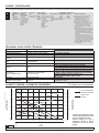
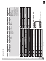
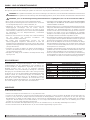
CAPACITY CURVES / CURVAS DE CAPACIDAD
*Tested at room temperature, using
water. Flooded pump with 3.5 inches
(80 mm), positive suction head.
*Ensayo realizado con agua a
temperatura ambiente y bomba
inundada en 80 mm de succión
positiva.
AIR CONSUMPTION
CONSUMO DE AIRE
PUMP FLOW
CAUDAL
TECHNICAL DATA / DATOS TÉCNICOS
U.S. glp
L/min
8
7
6
5
4
3
2
1
0
45.8
33.8
31.8
24.7
17.7
10.6
3.5
0
Nl/min.
SCFM
114
100
87
72.5
58
43.5
29
14.5
0
bar
psi
1300
1100
900
700
500
300
100
0
AIR CONSUMPTION
CONSUMO DE AIRE
FLUID PRESSURE
PRESIÓN DE FLUIDO
0 6.6 13.2 19.8 26.4 33 39.6 46.2 52.8
0 25 50 75 100 125 150 175 200
30 psi / 2 bar
87 psi / 6 bar
102 psi / 7 bar
58 psi / 4 bar
102 psi / 7 bar
87 psi / 6 bar
58 psi / 4 bar
30 psi / 2 bar
FLOW
CAUDAL
EN
ES

2021_12_15-12:00
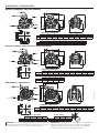
DIMENSIONS / DIMENSIONES
DIN DN25/ANSI 1”
DIN DN25
ANSI 1”
(1” BSP-F/NPT-F)
(1” BSP-F/NPT-F)
(1” BSP-F/NPT-F)
(1” BSP-F/NPT-F)
(1” BSP-F/NPT-F)
(1” BSP-F/NPT-F)
(1” BSP-F/NPT-F)
(1” BSP-F/NPT-F)
(1” BSP-F/NPT-F)
METALLIC-ALUMINIUM / METÁLICA-ALUMINIO
METALLIC-STAINLESS STEEL / METÁLICA-ACERO INOXIDABLE
NON METALLIC / NO METÁLICA
DIMENSIONS / DIMENSIONES
DIMENSIONS / DIMENSIONES
DIMENSIONS / DIMENSIONES
ATTACHMENT / FIJACIONES
ATTACHMENT / FIJACIONES
ATTACHMENT / FIJACIONES FLANGE / BRIDA
ØH
J
ØI
(3/8” NPSM)
(3/8” NPSM)
(3/8” NPSM)
DIN DN25/ANSI 1”
IMPORTANT: When doing a pump maintenance that implies manifold
disassembling and pump is fitted with PTFE o-rings (white colour), they
must be replaced by new ones in order to avoid fluid leakages”.
IMPORTANTE: Cuando realice un mantenimiento en la bomba que
implique desmontaje de los colectores y la bomba esté configurada
con juntas de PTFE (color blanco), estas tienen que ser reemplazadas
por unas nuevas con objeto de evitar fugas de fluido”.
A A1 B C D E E1 E2 F
(mm) 280 298 281 308 205 52 255 55 278
in. (“) 11 3/128” 11 47/64” 11 1/16” 12 1/8” 8 9/128” 2 3/64” 10 5/128” 2 21/128” 10 121/128”
G G1 G2 H H1 J J1 K
(mm) 175 154 9 140 127-137 102 158 10
in. (“) 6 57/64” 6 1/16” 23/64” 5 33/64” 5“-5 25/64” 4 1/64” 6 7/32” 25/64”
A A1 B C D E E1 E2 F
(mm) 302 320 295 364 232 60 280 40 311
in. (“) 11 57/64” 12 19/32” 11 39/64” 14 21/64” 9“ 9/64” 2 23/64” 11 3/128” 1 37/64” 12 1/4”
G G1 G2 G3
(mm) 175 154 180 9
in. (“) 6 57/64” 6 1/16” 7 11/128” 23/64”
Ø H Ø I J
(mm) 85 79,4 17
3 11/32” 3 1/8” 43/64”
A A1 B C D E E1 E2 F
(mm) 280 298 281 304 200 48 255 55 274
in. (“) 11 3/128” 11 47/64” 11 1/16” 11 31/32” 7 7/8” 1 57/64” 10 5/128” 2 21/128” 10 101/128”
G G1 G2 G3
(mm) 175 154 175 9
in. (“) 6 57/64” 6 1/16” 6 57/64” 23/64”

4855 833 R. 12/21
SAMOA Industrial, S.A. · Pol. Ind. Porceyo, I-14 · Camino del Fontán, 831 · 33392 - Gijón - Spain · Tel.: +34 985 381 488 · www.samoaindustrial.com
2021_12_15-12:00
EN
In this document you will find warnings and cautions for installation, use and maintenance of the pumps.
Here’s the meaning of symbols you may find in this document and general warnings that you should keep in mind.
WARNING: This symbol aware that there is a danger of serious bodily injury or death if you ignore the warning described.
CAUTION: This symbol aware that there is a danger of personal injury or property damage if you ignore the caution described.
• This equipment is for professional use only.
• Do not degrade the integrity of the equipment. Use only original
replacement components from Samoa Industrial, S.A.
• Fluids not suitable for the pump can cause damage to the pump unit
and involve risk of serious personal injury. Always consult Samoa
Industrial, S.A. if you have any questions about the compatibility within
the fluids and the pump materials, including elastomers.
• Install and use the pump according to all local and national regulations
and abide all health and safety laws or legislation.
• The pump can produce fluid pressures equal to the air supply pressure.
Do not exceed the maximum allowable pressure of 120 psi (8 bar) air
supply. The total hydraulic pressure (differential pressure + system)
should never exceed 120 psi (8 bar).
• Never use a pump that leaks, that is damaged, that is corroded or
otherwise it may lack the capacity to contain the fluid.
• Frequently check that the bolts on the diaphragm cover of the pump
are torqued correctly.
• Do not use a model with aluminium wetted surfaces to pump fluids for
human consumption, there is a possibility of trace contamination of lead.
• Danger of explosion if used 1,1,1-trichloroethane, methylene chloride
or other halogenated hydrocarbon solvents with aluminium wetted
materials. It could cause serious injury and property damage.
• Inside the pump, diaphragms separate the fluid that is being pumped
from the air supply. If a diaphragm breaks, the fluid can leak out of the
air exhaust and contaminate the environment.
• When handling hazardous fluids, always route the air exhaust into a
suitable container and locate it in a safe place. (Optional conection
system at customer’s request. Not supplied with the unit).
• When the fluid source level is situated higher than the pump, (flooded
suction), the outlet tank must be at a higher level than the product to
prevent spills.
• For pumps handling hazardous fluids that are a danger to humans or
to the environment, install a suitable container surrounding the pump
to prevent any leaks or spills.
• Ensure that the operators of this equipment are trained on the
operation and limitations. Use safety equipment as safety goggles or
other equipment required.
WARNING: CAREFULLY READ THE INSTRUCTIONS AND WARNINGS BEFORE OPERATING THE EQUIPMENT!
WARNINGS AND CAUTIONS
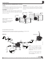
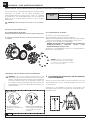
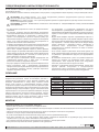
Air operated double diaphragm pumps are air-powered, reciprocating
positive displacement pumps with two pumping chambers. Two
diaphragms, centrally located in the chambers, separate the compressed
air (dry side) from the fluid being pumped (wet side). A shaft transmits
the reciprocating motion of one diaphragm to the other. A directional
valve alternatively distributes the air from one chamber to the other; thus
a reciprocating movement of the diaphragms is created. With each
stroke, fluid is discharged by one of the diaphragms whilst the opposite
diaphragm sucks new fluid into the expanding chamber. Check valves,
two on the discharge side and two on the suction side, control and direct
the fluid flow.
MATERIAL TEMPERATURE RANGE
PTFE 5 ºC - 105 ºC / 41 ºF - 221 ºF
NBR 10 ºC - 80 ºC / 50 ºF - 176 ºF
Acetal 10 ºC - 90 ºC / 50 ºF - 194 ºF
Hytrel®10 ºC - 90 ºC / 50 ºF - 194 ºF
Neopreno -18 ºC - 93 ºC / 0 ºF - 200 ºF
Santoprene®-29 ºC - 135 ºC / -20 ºF - 275 ºF
Viton®-10 ºC - 177 ºC /-4 ºF - 351 ºF
Polypropylene 10 ºC - 80 ºC / 50 ºF - 176 ºF
DESCRIPTION
• Remove the pump from its package and install it on the chosen location.
• Try to minimize the suction head. Install the pump as close as possible to the fluid being pumped.
• Remember to have enough space around the pump to perform maintenance tasks.
• Keep in mind to connect the inlet and outlet of the pump correctly.
• In case of diaphragm pump failure, the air exhaust will expel the product being pumped.
• When the pump is installed in a place where a spill of fluid can cause an environmental impact, the exhaust should be directed to a place.where
this spill could be contained.
• When installing the pump in its place, use brackets to secure its base.
• Fasten all bolts with the torques contained in this manual.
INSTALLATION RECOMMENDATIONS
INSTALLATION

5
R. 12/21 855 833
SAMOA Industrial, S.A. · Pol. Ind. Porceyo, I-14 · Camino del Fontán, 831 · 33392 - Gijón - Spain · Tel.: +34 985 381 488 · www.samoaindustrial.com
2021_12_15-12:00
EN
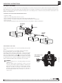
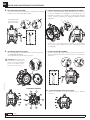
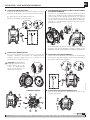
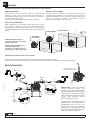
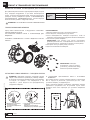
FLOODED:
The pumping system was designed with positive pressure at the inlet.
This is the best possible installation when you need to evacuate the liquid
from the drum or tank, or when working with viscous fluids.
Not recommended for hazardous fluids.
SELF-PRIMING:
Pump is designed to generate vacuum. It is possible to evacuate all the air
from a hose or pipe without damaging the pump. Maximum suction
height is (5 m) 16.5 ft, with the suction hose empty and up to 8 m (26.25
ft) with the hose primed.
NOTE: Use a pressure regulator with
built-in filter inlet.
NOTE: The compressed air supply must
be between 1,5 bar (20 psi) and
8 bar (120 psi).
INSTALLATION
FLOODED
SUBMERGED
SELF-PRIMING
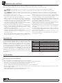
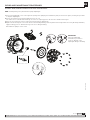
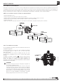
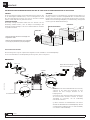
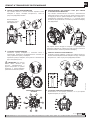
RECOMMENDED INSTALLATION
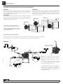
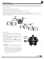
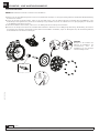
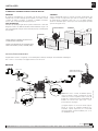
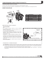
The figure below shows the recommended configuration for the installation of a diaphragm pump.
Read the warnings and recommendations of the previous page before starting.
Apply PTFE tape
to threads at assembly
NOTE: To use the top pump connection,
remove the plug and install the outle hose
using a connector compatible with pump
threads. Use the plug to close the standard
pump outlet. Use Teflon tape to seal the new
plug placement.
(*) Stainless steel manifold top and bottom
pump connections: Only available under
special request (Ask Samoa Industrial, S. A. or
your local distributor).
METALLIC
OUTLET
DISCHARGE
DRAINING
VALVE
INLET
MAX. 7 bar
OPTION
OPTION
3/8”
3/8”
1”
FLUID
INLET
SUCTION
DRAINING
VALVE
OPTION
1”
>=1”
>=1”
SUBMERGED:
All pumps can be immersed in fluids. It is important to verify that all
components that are in contact with the fluid are chemically compatible.
In this case, air exhaust and fluid must be carried by hoses (optional air
connection).
DP PUMPS ARE VERY EASILY CONFIGURED AND EASY TO INSTALL

6855 833 R. 12/21
SAMOA Industrial, S.A. · Pol. Ind. Porceyo, I-14 · Camino del Fontán, 831 · 33392 - Gijón - Spain · Tel.: +34 985 381 488 · www.samoaindustrial.com
2021_12_15-12:00
EN
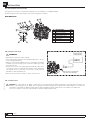
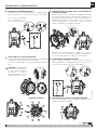
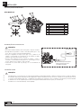
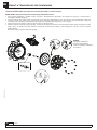
• Optional kit is required for remote exhaust.
• Unscrew the 4 bolts and remove the standard muffler (pos. 1-10, pos.
1-12) in pump part drawing.
• Place the remote exhaust adaptor (pos. 1-41), (remember to install the
included o-ring on its housing, (1-40). Screw the four bolts (pos. 1-42)
previously removed.
• Connect a hose to the new exhaust port and install the muffler at the
end of the hose. Use a hose with the same diameter as the exhaust port
3/4” NPT. (If the hose is more than 1.5 m (5 feet), consult your local
distributor or Samoa Industrial, S.A.).
• Have a moat, a protective housing, etc. at the end of the hose.
WARNING
INSTALLATION
AIR EXHAUST DISPOSAL
RECOMMENDED INSTALLATION
The figure below shows the recommended configuration for the installation of a diaphragm pump.
Read the warnings and recommendations of the previous page before starting.
NON-METALLIC
Nº DESCRIPTION Qty.
1Bolt 4
2Spring lock washer 4
3Flat washer 4
4Standard pipe flange 1
5Gasket 1
6Flat washer 4
7Nut 4
REMOTE EXHAUST ADAPTER KIT
(SEE PUMP PARTS DRAWING)
WARNING: To ensure that the air supply is sufficient to meet the demand of the pump, the diameter of the pipe must be equal to the
diameter of the supply port of the pump. Choose auxiliary air treatment equipment and fittings with sufficient airflow to exceed the air
consumption of the pump. In addition, peripheral air treatment equipment must be installed as close as possible to the pump unit.
The use of a coupler to connect the hoses aids future operation and maintenance tasks.
AIR CONNECTION

7
R. 12/21 855 833
SAMOA Industrial, S.A. · Pol. Ind. Porceyo, I-14 · Camino del Fontán, 831 · 33392 - Gijón - Spain · Tel.: +34 985 381 488 · www.samoaindustrial.com
2021_12_15-12:00
EN
THIS PUMP IS SELF-PRIMING
To prime it the first time, you must connect the air pump supply to a low pressure using the pressure regulators while keeping the outlet valve open.
When fluid begins to flow from the pump outlet, the pump is primed. For regulation of fluid pressure, the unit must be supplied with an air pressure
between 1,5 and 8 bar (20 and 120 psi). Adjust the discharge valve on the discharge side to control flow. For the performance characteristics of the
pump see the capacity curve.
• Stop the air supply.
• Make sure for your safety that the air valve is closed.
• Close the discharge valve and the suction valve. Open inlet and outlet drain valves.
• Open the air valve of the pump, running bring on the pump and flushing the remaining fluid.
• Close the air valve.
• After ensuring that the pump was turned off and the pressure was released, pump is ready for its maintenance.
WARNING
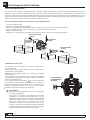
Connect grounding wires to the pump, piping and all other
equipment too.
When the pump operates ungrounded or with an incorrect
connection, friction between parts and abrasion caused by some
fluids that flow inside the pump, can generate static electricity.
Moreover, according to the type of fluid pump and the
installation environment (such as gases in the air or the type of
the surrounding facilities) static electricity can cause fire or
electric shock.
When installing the pump, be sure to perform grounding in the specified
location.
Also connect ground wires for the auxiliary equipment and piping.
Use a grounding cable of at least 12 gauge (2.0 mm2).
If the pump you have purchased is valid for Atex, a specific Atex manual
will accompany this one. Read this manual before operating the pump.
If the unit is marked with the symbol , it can be used in potentially
explosive atmospheres. Below this symbol, in the nameplate of the pump,
are indicated the areas for which the equipment is approved. You will also
find the maximum allowable surface temperature in the same plate.
OPERATING INSTRUCTIONS
STOPPING THE PUMP FOR MAINTENANCE TASKS
GROUNDING THE PUMP
THE POSITION OF THE
GROUND WIRE
DISCHARGE
VALVE
AIR VALVE
SUCTION
VALVE
INLET
DRAIN VALVE
OUTLET
DRAIN
VALVE

8855 833 R. 12/21
SAMOA Industrial, S.A. · Pol. Ind. Porceyo, I-14 · Camino del Fontán, 831 · 33392 - Gijón - Spain · Tel.: +34 985 381 488 · www.samoaindustrial.com
2021_12_15-12:00
EN
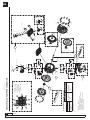
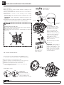
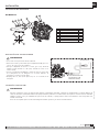
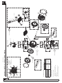
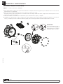
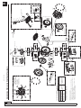
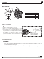
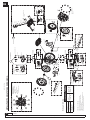
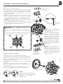
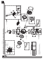
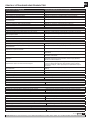
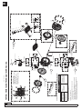
METALLIC PUMP PARTS DRAWING
1
2
6
AIR SENSOR
1_30
1_31
1_32
1_33
1_34
1_35
1_36
2_6 (=2_4) (=1_13)
2_9
2_3
(*)2_26 (=2_24)
(*)2_22
(*) STAINLESS STEEL
6
5_3
5_1
5_2 5_1
HARD SEATS + SEALS
SOFT SEATS
(*)2_28
2_1
(*)STAINLESS
STEEL
1_10
1_11
1_7
1_1
1_2
1_3
1_4
1_5
1_13 (=2_4) (=2_6)
(*)1_27
1_8
1_9 1_1
1_6
6
2_7 2_8
STANDARD EXHAUST
REMOTE EXHAUST
PTFE-NBR-EPDM-F
7_2
7_1
7_3
1_21
1_20
2_4 (=2_6) (=1_13)
(*)2_24
7_1
7_2
Hytrel®-Santoprene®
3_2 3_4 3_3
3_2
3_1
HARD SEATS + SEALS
5_3
5_1
5_2
SOFT SEATS
5_1
2_2
2_5
(*)2_23
(*)2_25
(*) STAINLESS STEEL
1_12
1_10
1_41
1_40
1_42
BODY
BALLS
2
BODY
7
1
AIR VALVE
DIAPHRAGMS
2_8
2_7
6BALLS
2
LUBRICATION / SEALANTS
- Apply mounting grease to all O-ring.
- Apply medium strength sealing to threards at
assembly (type LOCTITE 243).
- Apply anti-seize compound to threads when
using stainless steel fasteners.
SEATS 4
5SEALS
SEATS 4
5SEALS
4
3SEALS
PUSHING ROD
BUSCHING
SEALS
REGULAR MAINTENANCE SCREWS AND TOOLS
SCREW TYPE REQUIRED TOOL
DIRECTIONAL VALVE
Hex flanged head
screw M8
Socket wrench
Metric: 13 mm
Standard: 1/2””
FLUID MANIFOLDS
(Valve, seat and seals)
DIAPHRAGM COVERS
Diaphragm and central
pushing rod)
*Further maintenance (Air Sensors) will require
an Allen wrench: Metric 3 mm
21
7
95
3
8
10
6
4
ATTENTION! TIGHTENING SEQUENCE!: TORQUE REQUIEREMENTS
DIAPHRAGM COVER:
132 LBF·IN (15 N·M)
DIRECTIONAL VALVE:
70 LBF·IN (8 N·M)
MANIFOLDS:
132 LBF·IN (15 N·M)

9
R. 12/21 855 833
SAMOA Industrial, S.A. · Pol. Ind. Porceyo, I-14 · Camino del Fontán, 831 · 33392 - Gijón - Spain · Tel.: +34 985 381 488 · www.samoaindustrial.com
2021_12_15-12:00
EN
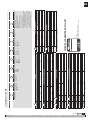
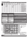
AIR VALVE
AIR VALVE AIR SENSORS REMOTE EXHAUST
POS 1_1 to 1_13 POS 1_30 to 1_36 POS 1_40 to 1_42
A558525 558527 558562
CENTRAL BODY AND MANIFLOD
CENTRAL BODY INLET MANIFLOD OUTLET MANIFLOD
POS 2_1 POS 2_2 POS 2_3
BSP THREADS NPT THREADS BSP THREADS NPT THREADS
A755123.001 755126.001 755126.301 755125.001 755125.301
S855052 855054 855054.300 855053 855053.300
PUSH ROD REPAIR KIT
PUSH ROD SEALS KIT CODE NUMERICAL CODING 55XXXX
S V 558556 -
S E 558557 -
S T 558566 -
S N 558554 555010/555030
SEATS VALVE REPAIR KIT
SEATS SEALS KIT CODE NUMERICAL CODING 55XXXX
A N 558539 -
A V 558540 -
A E 558541 -
A T 558542 -
S T 558551 -
N558535 555030
H558552 555010
M558553 -
BALL VALVE REPAIR KIT
KIT CODE NUMERICAL CODING 55XXXX
T558529 -
C558528 551010/555030
S558530 -
N558531 -
DIAPHRAGMS
KIT CODE NUMERICAL CODING 55XXXX
H558521 555010
M558523 -
N558561 555030
T558522 -
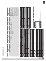
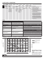
TECHNICAL CHARACTERISTICS LABEL
MODEL:
55XXXX (numerical coding)
DP200XXXXXXXXX (alphanumeric coding)
1
2
3
5
4
4
6
7
METALLIC PUMP
DP200XXXXXXXXXX
AIR VALVE BODY PUMP PUSH ROD SEALS SEATS BALLS DIAPHRAGMS CONECTIONS OPCIONS
A Aluminum A Aluminum
S Stainless steel
S Stainless steel N NBR
V FKM
E EPDM
T PTFE
S Stainless steel
A Aluminum
P Polypropylene
N NBR
M Santoprene®
H Hytrel®
T PTFE
C POM
S Stainless steel
N NBR
H Hytrel®
T PTFE
M Santoprene®
N NBR
B BSP
N NPT
A Standard pump
B Remote exhaust kit included
C Diaphragm leak detector
D Cycle sensor
E Externally controlled with
solenoid valve (not included)
F Nose muffler included
G Externally controlled with solenoid valve
(not included) and inductive end of
stroke sensors NPN (included)
I Externally controlled with solenoid valve
(not included) and inductive end of
stroke sensors ATEX-Namur (included)
U Pump suitable for UV fluids
123456789

10 855 833 R. 12/21
SAMOA Industrial, S.A. · Pol. Ind. Porceyo, I-14 · Camino del Fontán, 831 · 33392 - Gijón - Spain · Tel.: +34 985 381 488 · www.samoaindustrial.com
2021_12_15-12:00
EN
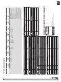
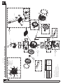
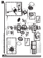
NON-METALLIC PUMP PARTS DRAWING
6
HARD SEATS + SEALS
5_3
5_1
5_2
SOFT SEATS
5_1
2
BODY
.
2
3
ATTENTION! TIGHTENING SECUENCE
21
7
95
3
8
10
6
4
1
AIR SENSOR
1_30
1_31
1_32
1_33
1_34
1_35
1_36
2_2
2_5
6BALLS
PTFE-NBR-EPDM-F
7_2
7_1
7_3
7_1
7_2
Hytrel®-Santoprene®
7
DIAPHRAGMS
3_2 3_4 3_3
3_2
3_1
2
2_6 (=1_13)
2_3
BODY
6
5_3
5_1
5_2 5_1
HARD SEATS + SEALS
SOFT SEATS
1_20
2_4 (=2_5)
1_21
1_13 (=2_6)
STANDARD EXHAUST
REMOTE EXHAUST
1_10
1_11
1_7
1_1
1_2
1_3
1_4
1_5
1_8
1_9 1_1
1_6
1_12
1_10
1_41
1_40
1_42
2_7
2_1
6BALLS
1_7
2_8
2
BODY
1
AIR VALVE
TORQUE REQUIEREMENTS
DIAPHRAGM COVER:
132 LBF·IN (15 N·M)
DIRECTIONAL VALVE:
70 LBF·IN (8 N·M)
MANIFOLDS:
132 LBF·IN (15 N·M)
LUBRICATION / SEALANTS
- Apply mounting grease to all O-ring.
- Apply medium strength sealing to threards at
assembly (type LOCTITE 243).
- Apply anti-seize compound to threads when
using stainless steel fasteners.
SEATS 4
5SEALS
SEATS 4
5SEALS
4
3SEALS
PUSHING ROD
BUSCHING
SEALS
REGULAR MAINTENANCE SCREWS AND TOOLS
SCREW TYPE REQUIRED TOOL
DIRECTIONAL VALVE
Hex flanged head
screw M8
Socket wrench
Metric: 13 mm
Standard: 1/2””
FLUID MANIFOLDS
(Valve, seat and seals)
DIAPHRAGM COVERS
Diaphragm and central
pushing rod)
*Further maintenance (Air Sensors) will require an Allen wrench: Metric 3 mm

11
R. 12/21 855 833
SAMOA Industrial, S.A. · Pol. Ind. Porceyo, I-14 · Camino del Fontán, 831 · 33392 - Gijón - Spain · Tel.: +34 985 381 488 · www.samoaindustrial.com
2021_12_15-12:00
EN
CENTRAL BODY AND MANIFLOD
CENTRAL BODY INLET MANIFLOD OUTLET MANIFLOD
POS 2_1 POS 2_2 POS 2_3
BRIDA DIN/ANSI BRIDA DIN/ANSI
P755552 896642 755560
B755553 896643 894637
W755556 896646 755561
PUSH ROD REPAIR KIT
PUSH ROD SEALS CÓD. KIT NUMERICAL CODING 55XXXX
ATEX PUMP NO ATEX PUMP -
S V 558556 558555 555164
S E 558557 558558 -
S T 558566 558560 -
Y T 558559 -
DP200XXXXXXXXXX
123456789
AIR VALVE
AIR VALVE AIR SENSORS REMOTE EXHAUST
POS 1_1 a 1_13 POS 1_30 a 1_36 POS 1_40 a 1_42
P558525 558527 558562
SEATS VALVE REPAIR KIT
SEATS SEALS KIT CODE NUMERICAL CODING 55XXXX
P V 558544 555164
P E 558545 -
P T 558546 -
C V 558536 -
C E 558537 -
C T 558538 -
W T 558548 -
H _ 558552 -
M _ 558553 -
BALLS VALVE REPAIR KIT
KIT CODE NUMERICAL CODING 55XXXX
T558529 555164
C558528 -
S558530 -
N558531 -
DIAPHRAGMS
KIT CODE NUMERICAL CODING 55XXXX
H558521 555164
M558523 -
N558561 -
T(1) 558522 -
(2) 558567 -
TECHNICAL CHARACTERISTICS LABEL
AIR VALVE BODY PUMP PUSH ROD SEALS SEATS BALLS DIAPHRAGMS CONECTIONS OPTIONS
P Polypropylene P Polypropylene
B Conductive PP
W PVDF
S Stainless steel
Y Hastelloy® C
N NBR
V FKM
E EPDM
T PTFE
P Polypropylene
C POM
W PVDF
M Santoprene®
H Hytrel®
T PTFE
C POM
S Stainless steel
N NBR
H Hytrel®
T PTFE
M Santoprene®
N NBR
F Flange A Standard pump
B Remote exhaust kit included
C Diaphragm leak detector
D Cycle sensor
E Externally controlled with
solenoid valve (not included)
F Nose muffler included
G Externally controlled with solenoid valve
(not included) and inductive end of
stroke sensors NPN (included)
I Externally controlled with solenoid valve
(not included) and inductive end of
stroke sensors ATEX-Namur (included)
U BPump suitable for UV fluids
1
2
3
5
4
4
6
7
(1) For pump fitted with stainless steel central pushing rod.
(2) For pump fitted with hastelloy® C central pushing rod.
MODEL:
55XXXX (numerical coding)
DP200XXXXXXXXX (alphanumeric coding)
NON-METALLIC PUMP

12 855 833 R. 12/21
SAMOA Industrial, S.A. · Pol. Ind. Porceyo, I-14 · Camino del Fontán, 831 · 33392 - Gijón - Spain · Tel.: +34 985 381 488 · www.samoaindustrial.com
2021_12_15-12:00
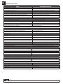
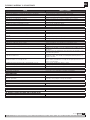
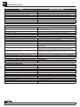
EN TROUBLESHOOTING
CAUSE RECOMMENDED MEASURE
THE PUMP DOES NOT WORK
The discharge valve on the discharge side is not open. Open the discharge valve on the discharge side.
No air supply. Turn on the compressor and open the air valve and air regulator.
The air supply pressure is low. Check the compressor and the configuration of the air line.
Air leaks in connecting elements. Check the connection elements and the tightening of the screws.
The air pipes or ancillary equipment is clogged with mud. Check and clean the air line.
The exhaust port (muffler) of the pump is clogged with mud. Check and clean the exhaust port and muffler.
The fluid pipe is clogged with mud. Check and clean the fluid line.
Pump is clogged with mud. Remove, inspect and clean the pump body.
THE PUMP RUNS BUT NO FLUID COMES OUT
The valve on the suction side is not open. Open the valve on the suction side.
Too much suction or discharge height. Confirm the configuration of the pipe and reduce the height of the
same.
Fluid pipe discharge side (including the filter) is clogged with mud. Check and clean the fluid line.
Pump is clogged with mud. Dismantle the pump, check and clean.
The ball and ball seat is worn or damaged. Inspect and replace parts.
THE FLOW IS DECREASING
The air supply pressure is low. Check the compressor and the configuration of the air line.
The air line or peripheral equipment clogged with mud. Check and clean the air line.
Valve discharge side drive will not open normally. Adjust the discharge valve discharge side.
The air mixes with the fluid. Replenish fluid and check the configuration of the pipe on the suction side.
Cavitation occurs. Adjust air supply pressure and discharge pressure and reduce the suction.
Vibrations. Adjust air supply pressure and discharge pressure. Reduce the flow of the
inlet valve to adjust pressure and volume of fluid.
Ice formation in the air exhaust. Remove ice from the air bypass valve and check and clean the air filter.
Use a pipe in the exhaust air that the ice does not form in the muffler.
The fluid line (including the filter) plugged with mud. Check and clean the fluid pipe and strainer.
The exhaust port (muffler) of the pump is clogged with mud. Check and clean the exhaust port and muffler.
Pump is clogged with mud. Remove, inspect and clean the pump body.
LEAKAGE OF FLUID THROUGH THE HOLLOW EXHAUST (SILENCER)
The diaphragm is damaged. Remove and inspect the pump and replace the diaphragm.
IRREGULAR NOISE
The air supply pressure is too high. Adjust air supply pressure.
The pump is clogged with sludge particles larger than the diameter allowed. Remove, check and clean the pump body.
IRREGULAR VIBRATION
The elements of connection and the support of the pump are loose. Review each element of connection and tighten the screws.
The air supply pressure is too high. Adjust air supply pressure.
The range and ball valve vibrates. Adjust air supply pressure and exhaust pressure.
POWERED AIR LEAK PRESSURE OF 1,5 TO 8 BAR (20 TO 120 PSI)
Wear air valve. Replace air valve.
NO START-UP AND IS LEAKING AIR WITHOUT CYCLES
Stiff air sensors. Change air sensor.
Wear air valve. Replace.
IN FLUID WITH AIR BUBBLES
Diaphragm damaged. Replace diaphragm.
Suction hose loose or broken. Tighten or replace.

13
R. 12/21 855 833
SAMOA Industrial, S.A. · Pol. Ind. Porceyo, I-14 · Camino del Fontán, 831 · 33392 - Gijón - Spain · Tel.: +34 985 381 488 · www.samoaindustrial.com
2021_12_15-12:00
EN
REPAIR AND MAINTENANCE PROCEDURES
For proper operation of the pump and to prevent accidents which may
damage equipment and in the worst case, people, you must periodically
review the torques of the diaphragms covers and the DIRECTIONAL
VALVE. In the next table are shown the appropriate torques for this
purpose:
TORQUES
DP200
Diaphragm cover 132 lbf·in ( 15 N·m)
Directional valve 70 lbf·in ( 8 N·m)
Manifolds 132 lbf·in (15 N·m)
TORQUES NECESSARY FOR THE PROPER FUNCTIONING OF THE PUMP
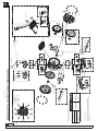
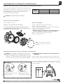
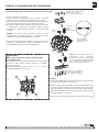
DIAPHRAGM MAINTENANCE
Before any intervention: DISCONNECT AIR SUPPLY OF THE PUMP.
IT IS NOT NECESSARY TO REMOVE THE PUMP FROM THE FLUID LINE.
REMOVING THE DIAPHRAGM:
1. Close inlet and discharge fluid valves.
2. Drain the fluid inside the pump.
3. Remove the directional valve while being careful not to damage the
seals between air valve and diaphagm.
4. Remove the diaphragm cover screws.
NOTE: To tighten these screws you must use a torque wrench
calibrated to (see torque table in this page).
5. Remove the cover by gently pulling back.
6. Remove the used diaphragms.
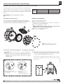
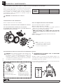
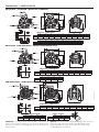
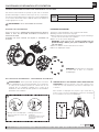
INSTALLING THE NEW DIAPHRAGMS - ASSEMBLING PROCEDURE
CAUTION: Follow next procedure to ensure the diaphragms are
correctly installed. If not followed diaphragm bead could be
extruded out of its housing with the resulting damage over the
diaphragm bead and thus possible fluid leaks or premature
diaphragm failure.
1. Correct assembly of the
diaphragm before the diaphragm
cover assembly.
2. Incorrect assembly of the
diaphragm.
Possible damage when
assembling the diaphragm cover.
Avoid instally the diaphragm without preparing the central rod in its
proper position. Diaphragm bead could be damaged when installing
diaphragm cover.
1. PREPARING THE CENTRAL ROD FOR DIAPHRAGM INSTALLATION
Using a soft head hammer displace the central rod out of the body
enough to install the diaphragm without deforming it.
NOTE: Be careful to not lose the seals
between valve and diaphragm cover.
CAUTION!
SOFT HEAD
CAUTION!: DO NOT OVERTIGHTEN FASTENERS.
ANTICIPATE A POSSITE LEAKAGE OF FLUID INSIDE THE PUMP.

14 855 833 R. 12/21
SAMOA Industrial, S.A. · Pol. Ind. Porceyo, I-14 · Camino del Fontán, 831 · 33392 - Gijón - Spain · Tel.: +34 985 381 488 · www.samoaindustrial.com
2021_12_15-12:00
EN REPAIR AND MAINTENANCE PROCEDURES
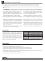
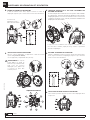
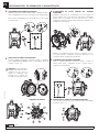
2. FIRST DIAPHRAGM ALIGNMENT
Using the soft head hammer, againg align the diaphragm bead until the
bead touches the housing without deformation.
The diaphragm bead
touches the housing
without deformation.
3. DIAPHRAGM COVER INSTALLATION
Place the diaphragm cover and approximate it using the bolts (follow
the TIGHTENING SEQUENCE).
Once approximated, torque @132 lbf·in (15 N·m).
CAUTION!: DP200 pump body
is fitted with two nipples that fit
with two holes in the diaphragm
cover to ensure that the cover is
placed in its correct possition.
TIGHTENING SEQUENCE
5. SECOND DIAPHRAGM ALIGNMENT
Install the remaining diaphragm and again, using the soft head hammer,
align the diaphragm bead until the bead touches the housing without
deformation.
6. SECOND DIAPHRAGM COVER INSTALLATION
Follow same procedure as for the first diaphramg cover described
inpoint nº3.
4. CENTRAL ROD RELEASE FOR SECOND DIAPHRAGM ALIGNMENT
Using an air gun fed with 1bar (15psi) maximum air pressure, inject
air in the air chamber of the diaphragm cover trough the hole nº1
meanwhile closing the holes nº2 and nº3 . Compresed air will push
out the central rod allowing the diaphagm installation without
deformation.
When we hole nº1 is feed with compressed air while closing nº2 and nº3
air enters in the chamber, displacing the central rod and allowing to install
the diaphragm.
1 2 3
SOFT HEAD
SOFT HEAD
1
2
4
3
7
95
8
106

15
R. 12/21 855 833
SAMOA Industrial, S.A. · Pol. Ind. Porceyo, I-14 · Camino del Fontán, 831 · 33392 - Gijón - Spain · Tel.: +34 985 381 488 · www.samoaindustrial.com
2021_12_15-12:00
EN
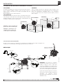
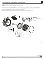
NOTE: Central pushing rod is placed between pump diaphragms.
1. Remove the diaphragms cover on the right side (looking at the pump by the identification plate) as shown in the figure, following the procedure
to “Replace diaphragms”.
2. Remove the shaft from its housing by pulling it from one end.
The Teflon® sleeve is threaded into the body. To remove use snap ring pliers in the two holes indicated in the figure.
3. Once the sleeve has been removed, remove the O-ring inside the pump body.
4. Replace the kit following the correct order shown in the assembly drawing. The O-ring between the body and teh sleeve may fall during installation,
apply mounting grease to attack the O-ring to the sleeve during threading.
Reassemble the pump in reverse order.
PUSHING ROD/CENTRAL BUSHING AND SEAL MAINTENANCE
REPAIR AND MAINTENANCE PROCEDURES
IMPORTANT:
Follow the diaphragm
maintenance procedure to
ensure no damage in the
diaphragm during its assembly.

16 855 833 R. 12/21
SAMOA Industrial, S.A. · Pol. Ind. Porceyo, I-14 · Camino del Fontán, 831 · 33392 - Gijón - Spain · Tel.: +34 985 381 488 · www.samoaindustrial.com
2021_12_15-12:00
EN REPAIR AND MAINTENANCE PROCEDURES
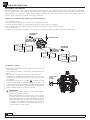
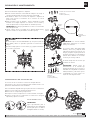
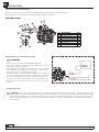
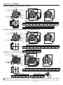
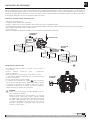
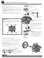
AIR SENSOR MAINTENANCE
The air sensors are on the inside part of the diaphragm covers.
To access them, follow the procedure for “Replacing diaphragms”.
Once removed the covers following procedure:
1. Remove the three screws that secure the air sensor to the top.
2. Remove all components of the sensor. Clean the area.
3. Introduce new components in the order shown.
4. Fit the remaining components in reverse order. Fit the side
cover and tighten the screws.
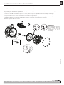
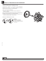
BALL VALVES AND SEATS MAINTENANCE
1. Close fluid valves.
2. Drain the fluid from inside the pump. Anticipate a drainage of fluid
from inside the pump.
3. Remove the inlet and outlet manifolds. Take note of the orientation of
the manifolds.
4. Install a new set of valves or seats according to these assembly
drawings. Tighten the manifold bolts with a maximum torque of 132
lbf·in ( 15 N·m).
IMPORTANT: Always approximate manifold bolts before final
tightening.
5. Assemble the directional valve being careful not to damage the O-rings and
tighten the screws with a maximum torque of 70 lbf·in ( 8 N·m).
This face always
downwards
Soft Seats
Outlet manifold bolts
25 mm (1”) long
15 N·m (132 lbf·in)
Hard seat
assembly
Inlet manifold bolts are
50 mm (1.96”) long
15 N·m (132 lbf·in)
IMPORTANT:
Follow the diaphragm
maintenance procedure to
ensure no damage in the
diaphragm during its assembly.
1
2
3
45
6
IMPORTANT:
Soft seats (NBR, Hytrel® and
Santoprene®) don’t need extra
seals and the seat is simetric.
Hard seats (PP, POM, PVDF,
aluminum, stainless steel), use
additional o-rings for sealing. See
seat position in the drawing to
ensure correct assembly. The
bigger diameter o-ring is
assembled over the seat and the
smaller one below it.
Balls must be always assembled
over the seat.
CAUTION!
CAUTION WHEN USING PIPE SEALS
DP200 pumps manifold fitted with PTFE (Teflon®) O-ring should be
tightened followy the shown sequence.
Alway tighten bolt (1) and (2), firstly to avoid damage the manifold
and the seals.
AIR SENSOR KIT: 558527
IMPORTANT: When doing a
pump maintenance that implies
manifold disassembling and
pump is fitted with PTFE o-rings
(white colour), they must be
replaced by new ones in order to
avoid fluid leakages”.

17
R. 12/21 855 833
SAMOA Industrial, S.A. · Pol. Ind. Porceyo, I-14 · Camino del Fontán, 831 · 33392 - Gijón - Spain · Tel.: +34 985 381 488 · www.samoaindustrial.com
2021_12_15-12:00
ENES
En este documento usted encontrará advertencias y precauciones para la instalación, uso y mantenimiento de las bombas.
A continuación le indicamos el significado de los símbolos y mencionamos unas advertencias generales que usted debe tener en cuenta.
ADVERTENCIA: Este símbolo alerta de que si no se siguen las instrucciones indicadas se puede producir una situación de lesión grave o muerte.
ATENCIÓN: Este símbolo alerta de daños o destrucción del equipamiento si no se siguen las instrucciones.
ADVERTENCIAS Y PRECAUCIONES
• Este equipo es únicamente para uso profesional.
• No altere la integridad del equipo. Use solamente componentes
originales de Samoa Industrial, S.A.
• Los fluidos no adecuados para la bomba pueden causar daños a la
unidad de la bomba e implicar riesgo de graves daños personales.
Consulte siempre al distribuidor de Samoa Industrial, S.A. si se tiene
alguna duda sobre la compatibilidad de los fluidos con los materiales
de la bomba, incluyendo los elastómeros.
• Instale y use siempre la bomba según la normativa y la legislación
sanitaria y de seguridad, tanto local como nacional.
• La bomba puede producir presiones de fluido iguales a la presión de
alimentación del aire. No exceder la presión máxima permitida de
alimentación de aire de 8 bar (120 psi). La presión hidráulica total
(presión del sistema + presión diferencial) no deberá exceder nunca 8 bar
(120 psi).
• No utilice nunca una bomba que tenga fugas o daños, esté corroída o
de otra forma carezca de la capacidad para contener el fluido interno
o la presión del aire.
• Comprobar con frecuencia que los tornillos de las tapas de la bomba
están correctamente apretados.
• No use modelos cuya parte húmeda esté basada en aluminio para
bombear productos de consumo humano, es posible que existan trazas
de plomo.
• Peligro de explosión si se usa 1,1,1-tricloroetano, cloruro de metileno
u otros disolventes de hidrocarburos halogenados en sistemas de fluido
a presión que tengan componentes de aluminio en la parte de fluido.
Podría causar graves daños materiales y personales incluso mortales.
• En el interior de la bomba, dos membranas separan el fluido bombeado
de la alimentación de aire. Si se rompe una membrana, el fluido puede
salir proyectado por el orificio de evacuación de aire.
• Cuando se manejen fluidos peligrosos, conecte siempre el orificio de
evacuación de aire a un recipiente adecuado y situado en un lugar
seguro. (Sistema de conexión opcional a petición del cliente. No se
suministra con el equipo).
• Cuando la fuente de producto se encuentre a un nivel más elevado que
la bomba (aspiración inundada), la impulsión deberá ser dirigida por
un tubo a un nivel más alto que el producto para impedir los derrames
causados por derivación sifónica.
• En las bombas que manejen fluidos peligrosos para las personas o el
medio ambiente, se debe instalar algún tipo de recipiente o contenedor
para recoger posibles fugas y evitar su derrame.
• Asegúrese de que el operario de este equipo esté formado en cuanto a
la operación, limitaciones y uso de equipamiento de seguridad como
gafas de seguridad u otro equipamiento requerido.
ADVERTENCIA: ¡Lea atentamente el manual de instrucciones y sus advertencias antes de empezar a operar con el equipo!
La bomba de membrana neumática es una bomba aspirante e impelente
de desplazamiento positivo, accionada por aire y con dos cámaras de
bombeo. Dos membranas ubicadas centralmente en las cámaras, separan
el aire comprimido (lado seco) del fluido bombeado (lado húmedo). Las
membranas están conectadas entre sí mediante un eje flotante cuyo
funcionamiento permite la minimización del flujo pulsante. Una válvula
(motor neumático) distribuye el aire de una cámara a la otra
alternativamente, produciendo así un movimiento recíproco de las
membranas.
En cada embolada, una de las membranas desplaza el fluido, mientras
que la membrana opuesta aspira nuevo fluido al interior de la cámara de
expansión. Cuatro válvulas de bola, dos en el lado de aspiración y dos en
el lado de impulsión, controlan y dirigen el flujo del fluido.
MATERIALES TEMPERATURA DE TRABAJO
PTFE 5 ºC - 105 ºC /41 ºF - 221 ºF
NBR 10 ºC - 80 ºC /50 ºF - 176 ºF
Acetal 10 ºC - 90 ºC /50 ºF - 194 ºF
Hytrel®10 ºC - 90 ºC /50 ºF - 194 ºF
Neopreno -18 ºC - 93 ºC /0 ºF - 200 ºF
Santoprene®-29 ºC - 135 ºC /-20 ºF - 275 ºF
Viton®-10 ºC - 177 ºC /-4 ºF - 351 ºF
Polipropileno 10 ºC - 80 ºC /50 ºF - 176 ºF
DESCRIPCIÓN
INSTALACIÓN
• Retire la bomba de la caja e instálela en el lugar elegido.
• Trate de reducir al mínimo la altura de aspiración.
• Recuerde disponer de espacio suficiente alrededor de la bomba para realizar las tareas de mantenimiento.
• Tenga siempre en cuenta usar correctamente la entrada y la salida de la bomba.
• En caso de fallo del diafragma el escape de aire de la bomba puede contener el producto bombeado.
• Cuando la bomba se instala en un lugar en el que pueda tener lugar un impacto en el medio ambiente, el escape debe orientarse hacia un lugar
donde no haya impacto ambiental.
• Cuando instale la bomba en su lugar, utilice los soportes en la base y asegure la bomba fijándola con los tornillos de amarre.
• Apriete todos los tornillos con el par recomendado en este manual.
RECOMENDACIONES INSTALACIÓN

18 855 833 R. 12/21
SAMOA Industrial, S.A. · Pol. Ind. Porceyo, I-14 · Camino del Fontán, 831 · 33392 - Gijón - Spain · Tel.: +34 985 381 488 · www.samoaindustrial.com
2021_12_15-12:00
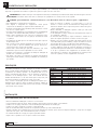
ENES
INUNDADA
El sistema de bombeo se diseñó para presión positiva en la aspiración.
Esta es la mejor forma de instalación cuando se necesite evacuar todo el
líquido del bidón o depósito, o cuando se trabaje con fluidos viscosos. No
recomendada para fluidos peligrosos.
ASPIRACIÓN:
La bomba DP está diseñada para generar vacío en la aspiración. Es posible
evacuar todo el aire de una manguera o tubería sin dañar la bomba. La
altura máxima de succión es de 5 m con la manguera de succión vacía y
hasta 8 m con la manguera cebada.
NOTA: Utilice un regulador de presión con
filtro incorporado en la entrada de aire.
NOTA: La presión de alimentación de aire
debe estar comprendida entre 1,5 bar (20
psi) y 8 bar (120 psi).
ASPIRACIÓN SUMERGIDA
INUNDADA
SUMERGIDO:
Todas las bombas DP se pueden sumergir en los fluidos. Es importante
que verifique que todos los componentes que están en contacto con el
fluido son químicamente compatibles. En este caso, las salidas de aire y
fluido deben ser conducidas al exterior mediante mangueras. (Sistema de
conexión de aire opcional).
LAS BOMBAS DP SON MUY FLEXIBLES Y FÁCILES DE INSTALAR INUNDADA
INSTALACIÓN RECOMENDADA
Nota: Para el empleo de la salida de fluido
superior, retire el tapón y emplee una manguera
con la conexión adecuada para las roscas de
la bomba.
Use el tapón retirado para cerrar la salida
convencional. Recuerde usar cinta de teflón para
lograr la estanqueidad de la unión.
(*) Conexión superior en colector de salida y
conexión inferior en colector de entrada a la
bomba de acero inoxidable: Solo disponible bajo
pedido especial (Pregunte a Samoa Industrial, S.A.
o su distribuidor local).
El esquema de abajo muestra la configuración de la instalación recomendada para una bomba de diafragma.
Lea las advertencias y recomendaciones de la página anterior antes de realizar dicha instalación
METÁLICA
SALIDA
VÁLVULA
DRENAJE
DESCARGA
ENTRADA
MAX. 7 bar
OPCIÓN
OPCIÓN
3/8”
3/8”
1”
ENTRADA
DE FLUIDO
VÁLVULA
DRENAJE
ASPIRACIÓN
OPCIÓN
1”
>=1”
>=1”
Aplique cinta de PTFE 1"
a las roscas en el montaje
INSTALACIÓN

19
R. 12/21 855 833
SAMOA Industrial, S.A. · Pol. Ind. Porceyo, I-14 · Camino del Fontán, 831 · 33392 - Gijón - Spain · Tel.: +34 985 381 488 · www.samoaindustrial.com
2021_12_15-12:00
ENES
• Es necesario el kit opcional de salida conducida.
• Retire los 4 tornillos y el silenciador que acompaña la bomba (pos. 1-10
y pos 1-12 en la sección de recambios).
• Coloque el adaptador de silencioso o remoto, (pos. 1-41). Recuerde
instalar la junta incluida en el kit (1-40). Atornille de nuevo los 4
tornillos (1-42).
• Conecte esa manguera al adaptador e instale un silencioso al otro lado
de la manguera. Use esa manguera con el mismo diámetro de
manguera y conexiones de 3/4” NPT.
• Disponga un foso, una caja de protección, etc. en el extremo de la
manguera.
ADVERTENCIA
INSTALACIÓN
DISPOSICIÓN DEL ESCAPE EXTERIOR
INSTALACIÓN RECOMENDADA
NO-METÁLICA
Nº DESCRIPCIÓN Qty.
1Tornillos 4
2Resorte arandela de bloqueo 4
3Arandelas planas 4
4Brida de tubería estándar 1
5Empaquetadura 1
6Arandelas planas 4
7Tuercas 4
ADVERTENCIA
Para que el suministro de aire sea suficiente para satisfacer la demanda de la bomba, el diámetro de la tubería debe ser igual al diámetro del
orificio de suministro de la bomba. También elija equipos auxiliares y materiales con suficiente flujo de aire para el consumo de aire de la bomba.
También considere el uso y la estabilidad de la presión de aire. Además, el equipo periférico debe estar instalado lo más cerca posible de la
unidad de la bomba.
El uso de un acoplador para conectar cada manguera facilita la operación y las tareas de mantenimiento.
CONEXIÓN TOMA DE AIRE
KIT DE ADAPTACIÓN PARA
ESCAPE REMOTO (VER
DESPIECE DE BOMBA)
ESCAPE REMOTO

20 855 833 R. 12/21
SAMOA Industrial, S.A. · Pol. Ind. Porceyo, I-14 · Camino del Fontán, 831 · 33392 - Gijón - Spain · Tel.: +34 985 381 488 · www.samoaindustrial.com
2021_12_15-12:00
ENES
ESTA BOMBA ES AUTO-CEBANTE.
Para cebarla la primera vez, es conveniente conectar el aire a la bomba a baja presión con el regulador de presión, manteniendo la válvula de salida abierta.
Cuando el fluido empieza a salir, la bomba está cebada. Para su regulación mediante presión de fluido se debe alimentar con presión de aire
comprendida entre 1,5 y 8 bar (20 - 120 psi). Ajuste la válvula de impulsión en el lado de descarga. Para la relación entre el flujo, la presión de
suministro de aire y la presión de descarga, vea la curva de capacidad.
• Corte el suministro de aire.
• Compruebe por su seguridad que la válvula de aire de la bomba esté cerrada.
• Cierre las válvulas de aspiración y descarga. Abra las válvulas de drenaje (aspiración e impulsión).
• Abra la válvula de aire de la bomba, ponga en funcionamiento la bomba y descargue el fluido remanente.
• Cierre la válvula de aire.
• Asegúrese de que la bomba se ha detenido y no existe presión en las líneas de fluido. La bomba está lista para el mantenimiento.
ADVERTENCIA:
Asegúrese de conectar conductores a tierra para la bomba,
tuberías y otros equipos conectados.
Cuando la bomba opera sin conexión a tierra o con una conexión
incorrecta, la fricción entre las piezas y la abrasión causada por
algunos fluidos que fluyen dentro de la bomba pueden generar
electricidad estática. Además, según el tipo de fluido a bombear
y el ambiente de la instalación (como gases en el aire o el tipo de
las instalaciones circundantes) la electricidad estática puede ser
causa de incendio o choque eléctrico.
• Cuando instale la bomba, asegúrese de realizar la conexión a tierra en
el lugar especificado.
• Conecte también conductores a tierra para los equipos auxiliares y las
tuberías.
• Utilice un cable con conexión a tierra de por lo menos 2,0 mm2.
• Si la bomba que ha adquirido es válida para Atex, a este manual lo
acompañará uno específico para Atex. Lea este manual antes de operar
con la bomba.
• Si la bomba viene marcada con el símbolo , esta puede ser usada
en atmósferas potencialmente explosivas. Debajo de este símbolo, en
las placa de identificación de la bomba, vienen indicadas las zonas para
las que el equipo está aprobado. Encontrará también la temperatura de
superficie máxima permitida en la placa de su bomba.
MODO DE OPERACIÓN
PARADA DE LA BOMBA PARA TAREAS DE MANTENIMIENTO
CONEXIÓN A TIERRA
POSICIÓN DEL
CABLE
A TIERRA
VÁLVULA DE
DESCARGA
VÁLVULA DE AIRE
VÁLVULA DE
ASPIRACIÓN
VÁLVULA
DE DRENAJE
ASPIRACIÓN
VÁLVULA
DE DRENAJE
IMPULSIÓN
Seite wird geladen ...
Seite wird geladen ...
Seite wird geladen ...
Seite wird geladen ...
Seite wird geladen ...
Seite wird geladen ...
Seite wird geladen ...
Seite wird geladen ...
Seite wird geladen ...
Seite wird geladen ...
Seite wird geladen ...
Seite wird geladen ...
Seite wird geladen ...
Seite wird geladen ...
Seite wird geladen ...
Seite wird geladen ...
Seite wird geladen ...
Seite wird geladen ...
Seite wird geladen ...
Seite wird geladen ...
Seite wird geladen ...
Seite wird geladen ...
Seite wird geladen ...
Seite wird geladen ...
Seite wird geladen ...
Seite wird geladen ...
Seite wird geladen ...
Seite wird geladen ...
Seite wird geladen ...
Seite wird geladen ...
Seite wird geladen ...
Seite wird geladen ...
Seite wird geladen ...
Seite wird geladen ...
Seite wird geladen ...
Seite wird geladen ...
Seite wird geladen ...
Seite wird geladen ...
Seite wird geladen ...
Seite wird geladen ...
Seite wird geladen ...
Seite wird geladen ...
Seite wird geladen ...
Seite wird geladen ...
Seite wird geladen ...
Seite wird geladen ...
Seite wird geladen ...
Seite wird geladen ...
Seite wird geladen ...
Seite wird geladen ...
Seite wird geladen ...
Seite wird geladen ...
Seite wird geladen ...
Seite wird geladen ...
Seite wird geladen ...
Seite wird geladen ...
Seite wird geladen ...
Seite wird geladen ...
Seite wird geladen ...
Seite wird geladen ...
Seite wird geladen ...
Seite wird geladen ...
Seite wird geladen ...
Seite wird geladen ...
Seite wird geladen ...
Seite wird geladen ...
Seite wird geladen ...
Seite wird geladen ...
-
 1
1
-
 2
2
-
 3
3
-
 4
4
-
 5
5
-
 6
6
-
 7
7
-
 8
8
-
 9
9
-
 10
10
-
 11
11
-
 12
12
-
 13
13
-
 14
14
-
 15
15
-
 16
16
-
 17
17
-
 18
18
-
 19
19
-
 20
20
-
 21
21
-
 22
22
-
 23
23
-
 24
24
-
 25
25
-
 26
26
-
 27
27
-
 28
28
-
 29
29
-
 30
30
-
 31
31
-
 32
32
-
 33
33
-
 34
34
-
 35
35
-
 36
36
-
 37
37
-
 38
38
-
 39
39
-
 40
40
-
 41
41
-
 42
42
-
 43
43
-
 44
44
-
 45
45
-
 46
46
-
 47
47
-
 48
48
-
 49
49
-
 50
50
-
 51
51
-
 52
52
-
 53
53
-
 54
54
-
 55
55
-
 56
56
-
 57
57
-
 58
58
-
 59
59
-
 60
60
-
 61
61
-
 62
62
-
 63
63
-
 64
64
-
 65
65
-
 66
66
-
 67
67
-
 68
68
-
 69
69
-
 70
70
-
 71
71
-
 72
72
-
 73
73
-
 74
74
-
 75
75
-
 76
76
-
 77
77
-
 78
78
-
 79
79
-
 80
80
-
 81
81
-
 82
82
-
 83
83
-
 84
84
-
 85
85
-
 86
86
-
 87
87
-
 88
88


in anderen Sprachen
- français: Samoa 555030
- español: Samoa 555030
- português: Samoa 555030
Verwandte Artikel
-
Samoa UP05B-BDS-CMA Instructions Manual
-
-
-
-
-
-
-
-
-
