
MKD
®
-C, MKD
®
-N
Product Safety Guide
Edition: -, January 2019
Part Number 904-200024-99
English Deutsch Français Italiano Português Español Русский
Original language is English. All other content is translated from the genuine English content.
For safe and proper use, follow
these instructions.
Keep them for future reference.

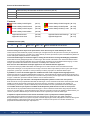
Record of Document Revisions
Revision Remarks
...
Table with lifecycle information of this document see (➜ # 79)
A, 01/2019 First edition
Contents
Product Safety Guide English (➜ # 3) Product Safety Guide Português (➜ # 47)
Product Safety Guide Deutsch (➜ # 23) Product Safety Guide Español (➜ # 49)
Product Safety Guide Français (➜ # 43) Product Safety Guide Русский (➜ # 51)
Product Safety Guide Italiano (➜ # 45)
Appendix/Dimensions (➜ # 55) Appendix/Faults and Warnings (➜ # 74)
Appendix/Connections (➜ # 57) Appendix/Approvals (➜ # 77)
Hardware Revision (HR)
MKD-N MKD-C Firmware WorkBench Remarks
A A from 1.18 from 1.18 MKD-C and MKD-N start revisions
Technical changes which improve the performance of the device may be made without prior notice!
This document is the intellectual property of Kollmorgen. All rights reserved. No part of this work may be reproduced
in any form (by photocopying, microfilm or any other method) or stored, processed, copied or distributed by electronic
means without the written permission of Kollmorgen.
Technische Änderungen zur Verbesserung der Leistung der Geräte ohne vorherige Ankündigung vorbehalten.
Dieses Dokument ist geistiges Eigentum von Kollmorgen. Alle Rechte vorbehalten. Kein Teil dieses Werkes darf in
irgendeiner Form (Fotokopie, Mikrofilm oder in einem anderenVerfahren) ohne schriftliche Genehmigung von Koll-
morgen reproduziert oder elektronisch verarbeitet, vervielfältigt oder verbreitet werden.
Sous réserve de modifications techniques apportés en vue d'amélioration des appareils!
Ce document est la propriété intellectuelle de Kollmorgen.Tous droits réservés. Sans autorisation écrite de
l'entreprise Kollmorgen, aucune partie de cet ouvrage n'a le droit d'être ni reproduite par des moyens quelconques
(impression, photocopie, microfilm ou autre procédure) ni traitée, polycopiée ou distribuée électronique.
Il produttore si riserva la facoltà di apportare modifiche tecniche volte al miglioramento degli apparecchi
Questo documento è la proprietà intellettuale di Kollmorgen. Tutti i diritti riservati. Nessuna parte del documento può
essere riprodotta in qualsiasi forma (fotocopia, microfilm o altro processo) senza l’approvazione scritta della ditta Koll-
morgen o rielaborata, riprodotta o diffusa mediante l’uso di sistemi elettronici.
Alterações técnicas que melhoram o desempenho do dispositivo podem ser feitos sem aviso prévio!
Este documento é uma propriedade intelectual da Kollmorgen. Todos os direitos reservados. Nenhuma parte deste
trabalho pode ser reproduzida sob qualquer forma (por fotocópia, microfilme ou qualquer outro método) ou
armazenado, processado, copiado ou distribuído por meios eletrônicos sem a permissão escrita da Kollmorgen.
Los cambios técnicos que mejoran el rendimiento del dispositivo pueden llevarse a cabo sin aviso previo.
Este documento es propiedad intelectual de Kollmorgen. Todos los derechos reservados. Ninguna parte de esta
obra, bajo concepto alguno, podrá reproducirse (por fotocopia, microfilm ni ningún otro método) ni almacenarse, pro-
cesarse, copiarse ni distribuirse por medios electrónicos sin el permiso por escrito de Kollmorgen.
Сохраняется право внесения технических изменений с целью усовершенствования приборов!
Настоящий документ является интеллектуальной собственностью Kollmorgen. Все права защищены.
Воспроизведение любой части данного издания в любой форме (фотокопия, микрофильм или иной метод) или
редактирование, размножение или распространение с помощью электронных систем без письменного
разрешения компании Kollmorgen запрещаются.
2 Kollmorgen | kdn.kollmorgen.com | January 2019

1 English
1.1 General 4
1.1.1 Notes for the Printed Edition (paper version) 4
1.1.2 Symbols Used 5
1.2 Product Safety 6
1.2.1 You should pay attention to this 6
1.2.2 Use as Directed 8
1.2.3 Prohibited Use 9
1.2.4 Warning note labels 9
1.3 Product life cycle handling 10
1.3.1 Transport 10
1.3.2 Packaging 10
1.3.3 Storage 10
1.3.4 Installation, setup and normal operation 11
1.3.5 Decommissioning 11
1.3.6 Maintenance and cleaning 11
1.3.7 Disassembly 11
1.3.8 System Repair 12
1.3.9 Disposal 12
1.4 Technical description and general data 13
1.4.1 Package Supplied 13
1.4.2 Part Number Scheme 14
1.4.3 Ambient Conditions in normal operation 15
1.4.4 Electrical Data 15
1.4.5 System limits 15
1.5 Safe Torque Off (STO) 16
1.6 Mechanical Installation 17
1.6.1 Important Notes 17
1.6.2 Guide to Mechanical Installation 17
1.7 Electrical Installation 18
1.7.1 Important Notes 18
1.7.2 Guide to electrical installation 18
1.8 Setup 19
1.8.1 Important Notes 19
1.8.2 Initial System Test 20
1.9 Troubleshooting the MKD System 21
MKD Product Safety Guide | 1 English
Kollmorgen | kdn.kollmorgen.com | January 2019 3

MKD Product Safety Guide | 1 English
1.1 General
This manual, the MKD-C/N Product Safety Guide, presents the relevant information for safe
installation and setup of MKD drive system modules MKD-C power supply and MKD-N servo
drive.
For full information refer to the MKD-C/N Installation Manual, to the AKD-N Installation
Manual and additional Kollmorgen documents.
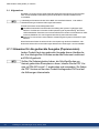
Additional documents include the following:
WorkBench Online Help: describes how to use the system in common applications. It
also provides tips for maximizing your system performance. The Online Help includes the
Parameter and Command Reference Guide which provides documentation for the para-
meters and commands used to program the system.
EtherCAT Communication: describes how to use the system in EtherCAT applications.
These documents can be found on the DVD in the drive package. All documents can be
downloaded from the Kollmorgen website www.kollmorgen.com.
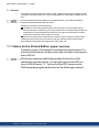
1.1.1 Notes for the Printed Edition (paper version)
A printed version of the manual is enclosed with each product. For
environmental reasons, the document was reduced in size and prin-
ted on DIN A5.
Should you experience difficulties reading the font size of the
scaled-down printed version, you can print and use the PDF ver-
sion in DIN A4 format 1:1. You can find the PDF version on the
DVD accompanying the product and on the Kollmorgen website.
4 Kollmorgen | kdn.kollmorgen.com | January 2019

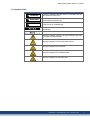
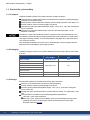
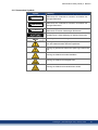
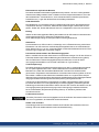
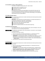
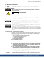
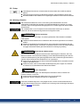
1.1.2 Symbols Used
Symbol Indication
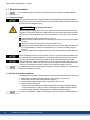
DANGER
Indicates a hazardous situation which, if not avoided, will res-
ult in death or serious injury.
WARNING
Indicates a hazardous situation which, if not avoided, could
result in death or serious injury.
CAUTION
Indicates a hazardous situation which, if not avoided, could
result in minor or moderate injury.
Indicates situations which, if not avoided, could result in prop-
erty damage.
This symbol indicates important notes.
Warning of a danger (general). The type of danger is specified
by the text next to the symbol.
Warning of danger from electricity and its effects.
Warning of danger from hot surface.
Warning of danger from suspended loads.
Warning of danger from automatic start.
MKD Product Safety Guide | 1 English
Kollmorgen | kdn.kollmorgen.com | January 2019 5

MKD Product Safety Guide | 1 English
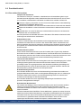
1.2 Product Safety
1.2.1 You should pay attention to this
Specialist staff required!
Only properly qualified personnel are permitted to perform such tasks as transport, install-
ation and setup. Qualified specialist staff are persons with expertise in transport, installation,
assembly, commissioning and operation of electrotechnical equipment.
Transport, storage, unpacking: only by personnel with knowledge of handling elec-
trostatically sensitive components.
Mechanical installation: only by personnel with mechanical expertise.
Electrical installation: only by personnel with expertise in electrical engineering.
Basic tests / setup: only by personnel with expertise in electrical engineering and drive
technology.
The qualified personnel must know and observe ISO 12100 / IEC 60364 / IEC 60664 and
national accident prevention regulations.
Read the documentation!
Read the available documentation before installation and commissioning. Improper handling
of the devices can cause harm to people or damage to property. The operator of systems
using the drive system must ensure that all personnel who work with the drive read and under-
stand the manual before using the drive.
Check Hardware Revision!
Check the Hardware Revision Number of the product (see product label). Hardware Revsion
Number of MKD-C and MKD-N can differ from each other. This number is the link between
your product and the manual. The product Hardware Revision Number must match the Hard-
ware Revision Number on the cover page of the manual.
Pay attention to the technical data!
Adhere to the technical data and the specifications on connection conditions. If permissible
voltage values or current values are exceeded, the devices can be damaged. Unsuitable
motor or wrong wiring will damage the system components. Check the combination of drive
and motor. Compare the rated voltage and current of the units.
Perform a risk assessment!
The manufacturer of the machine must generate a risk assessment for the machine, and take
appropriate measures to ensure that unforeseen movements cannot cause injury or damage
to any person or property. Additional requirements on specialist staff may also result from the
risk assessment.
The manufacturer should define periodic checks of the electrical components and applic-
ation.
Automatic Restart!
The drive might restart automatically after power on, voltage dip or interruption of the supply
voltage, depending on the parameter setting.
Risk of death or serious injury for humans working in the machine.
If the parameter DRV.ENDEFAULT for one MKD-N is set to 1, then place a warning sign to
the machine (Warning: Automatic Restart at Power On) and ensure, that power on is not pos-
sible, while humans are in a dangerous zone of the machine. In case of using an under-
voltage protection device, you must observe EN 60204-1:2006 chapter 7.5 .
6 Kollmorgen | kdn.kollmorgen.com | January 2019

Observe electrostatically sensitive components!
The devices contain electrostatically sensitive components which may be damaged by incor-
rect handling. Electrostatically discharge your body before touching the device. Avoid con-
tact with highly insulating materials (artificial fabrics, plastic film etc.). Place the device on a
conductive surface.
Hot surface!
Drives may have hot surfaces during operation. The housing can reach temperatures above
80°C. Risk of minor burns! Measure the temperature, and wait until the housing has cooled
down below 40 °C before touching it.
Earthing!
It is vital that you ensure that the drive is safely earthed to the PE (protective earth) busbar in
the switch cabinet. Risk of electric shock. Without low-resistance earthing no personal pro-
tection can be guaranteed.
Leakage Current!
Since the leakage current to PE is more than 3.5 mA, in compliance with IEC61800-5-1 the
PE connection must either be doubled or a connecting cable with a cross-section >10 mm²
must be used. Deviating measures according to regional standards might be possible.
Residual current protective or monitoring devices!
MKD-C with MKD-N can cause a d.c. current in the protective earthing conductor. Where a
residual current-operated protective (RCD) or monitoring (RCM) device is used for protection
in case of direct or indirect contact, only an RCD or RCM of Type B is allowed on the supply
side of MKD-C.
Lethal voltages!
The equipment produces high electric voltages up to 900V. Lethal danger exists at live parts
of the device. Do not open or touch the equipment during operation. Keep the IP 54 cabinet
doors closed during operation. Built-in protection measures such as insulation or shielding
may not be removed. Work on the electrical installation may only be performed by trained
and qualified personnel, in compliance with the regulations for safety at work, and only with
switched off mains supply, and secured against restart.
Never undo any electrical connections to the MKD while it is live. There is a danger of elec-
trical arcing with damage to contacts and personal injury. Wait at least 5 minutes after dis-
connecting the product from the supply voltages (mains supply and 24V supply) before
touching potentially live sections of the equipment (such as contacts) or removing any con-
nections.
Functional Safety
Safety functionality is not approved nor certified. Do not use this functionality in applications
with functional safety request.
Never modify the drive!
It is not allowed to modify the drive hardware without permission by the manufacturer. Open-
ing the housing causes loss of warranty.
MKD Product Safety Guide | 1 English
Kollmorgen | kdn.kollmorgen.com | January 2019 7

MKD Product Safety Guide | 1 English
1.2.2 Use as Directed
The MKD-C series power supplies are exclusively intended for operating MKD-N servo drive
modules within a cabinet and AKD-N decentralized servo drives.
The MKD-N family of servo drives is exclusively intended for driving suitable synchronous
servomotors with closed-loop control of torque, speed, and/or position.
MKD system modules are components that are built into electrical plants or machines and
can only be operated as integral components of these plants or machines. The manufacturer
of the machine must generate a risk assessment for the machine.
When the system modules are built into machines or plant, the drive must not be used until it
has been established that the machine or plant fulfills the requirements of the regional dir-
ectives.
Kollmorgen multi axes drive system
MKD must only be operated in a motion system with components from Kollmorgen. Required
additional Kollmorgen components are the mains chokes, hybrid string cables, hybrid motor
cables, motor power and feedback cables, servomotors.
Assembling
MKD modules must only be operated in environments suitable for the ambient conditions
defined on (➜ # 15).
Wiring
Use only Kollmorgen cables for connecting the system components.
Power supply
MKD-C must be powered from a 3 phase industrial supply network
(not more than 42 kA symmetrical rated current at 400 V and 480 V) via a mains choke 3YL.
MKD-N series drives must be powered by MKD-C intelligent power supply modules with DC
voltage from 55 VDC up to 800 VDC.
Fusing
The devices must be operated with fuse protection against power overload.
Motor voltage rating
The rated voltage of the motors must be at least as high as the DC bus link voltage divided by
√2 produced by the drive (U
nMotor
>=U
DC
/√2).
For the cases of group installations and of DC powered drives
MKD has not been evaluated by Kollmorgen, UL, or TÜV for group installations nor are rat-
ings defined for DC input voltage.
Auxiliary voltage supply, Standby power
Standby power for the drive strings must only be used for supplying the MKD-N electronics.
24 VDC supply unit must accord to PELV (EN 60204-1) requirements.
Safe torque off
Safety functionality is not approved nor certified. Do not use this functionality in applications
with functional safety request.
8 Kollmorgen | kdn.kollmorgen.com | January 2019

1.2.3 Prohibited Use
Other use than that described in chapter “Use as directed” is not intended and can lead to per-
sonnel injuries and equipment damage.
The system may not be used
with a machine that does not comply with appropriate national directives or standards,
for driving elevators,
in applications with continuous, operational short circuits to the external regen resistor
contacts.
in applications with any short circuits to the DC-Bus link contacts.
The use of the device in the following environments is also prohibited:
potentially explosive areas
environments with corrosive and/or electrically conductive acids, alkaline solutions, oils,
vapors, dusts
ships or offshore applications
Wiring the system with hybrid cables from other manufacturers than Kollmorgen is not
allowed. Changing Kollmorgen cables or connectors is not allowed.
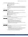
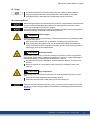
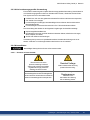
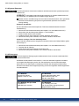
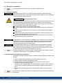
1.2.4 Warning note labels
If these signs are damaged, they must be replaced immediately.
1.2.4.1 Notes placed on the product
The minimum size of the
protective earthing conductor
shall comply with the local safety
regulations for high protectice
earthing conductor current.
Residual Voltage
Wait 5 minutes after removing
power before servicing.
MKD Product Safety Guide | 1 English
Kollmorgen | kdn.kollmorgen.com | January 2019 9

MKD Product Safety Guide | 1 English
1.3 Product life cycle handling
1.3.1 Transport
Transport the MKD modules in accordance with IEC 61800-2 as follows:
Transport only by qualified personnel in the manufacturer’s original recyclable packaging.
Avoid shocks while transporting.
Vibration/Shock: MKD modules are tested for environmental class 3M1 of IEC 60721-3-2.
Store at or below maximum stacking height of 8 cartons
Transport only within specified temperature ranges: -25 to +70 °C, max. rate of change 20
K/hour, class 2K3.
Transport only within specified humidity: maximum 95% relative humidity, no con-
densation, class 2K3.
The devices contain electrostatically sensitive components that can be damaged by incor-
rect handling. Electrostatically discharge yourself before touching the device. Avoid contact
with highly insulating materials, such as artificial fabrics and plastic films. Place the device
on a conductive surface.
If the packaging is damaged, check the unit for visible damage. Inform the shipper and the
manufacturer of any damage to the package or product.
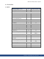
1.3.2 Packaging
The MKD packaging consists of recyclable cardboard with inserts and a label on the outside
of the box.
Model Package Dimensions
(mm) HxWxL
Total Weight
(kg)
MKD-C003007 580 x 350 x 170 22.5
MKD-N060007
580 x 350 x 110 8.5
MKD-N060607
MKD-N120007
MKD-N120607
MKD-N121207
MKD-N240007 580 x 350 x 110 9.5
MKD-N480007 580 x 350 x 140 11.5
1.3.3 Storage
Store the MKD modules in accordance with IEC 61800-2 as follows:
Store only in the manufacturer’s original recyclable packaging.
Store at or below maximum stacking height of 8 cartons
Store only within specified temperature ranges: -25 to +55 °C, max.rate of change 20
K/hour, class 1K4.
Storage only within specified humidity: 5 to 95% relative humidity, no condensation, class
1K3.
Store the MKD in accordance with the following duration requirements:
Less than 1 year: without restriction.
More than 1 year: capacitors in the MKD-C must be re-formed before setting up and
operating the system. Re-forming procedures are described in the Kollmorgen
Developer Network (Forming).
10 Kollmorgen | kdn.kollmorgen.com | January 2019

1.3.4 Installation, setup and normal operation
Installation and setup information are given in this Guide:
Mechanical installation (➜ # 17)
Electrical installation (➜ # 18)
Setup (➜ # 19)
Normal operation tested for environmental class 3K3 according to IEC 61800-2 (➜ # 15).
The manufacturer of the machine defines the necessary end user expertise based on the risk
assessment for the machine and describes the requirements for normal operation based on
the application.
1.3.5 Decommissioning
Only professional staff who are qualified in electrical engineering are allowed to decom-
mission parts of the system.
DANGER: Lethal Voltages!
There is a danger of serious personal injury or death by electrical shock or electrical arcing.
Switch off the main switch of the switchgear cabinet.
Secure the system against restarting.
Block the main switch.
Wait at least 5 minutes after disconnecting.
1.3.6 Maintenance and cleaning
The device does not require maintenance. Opening the device voids the warranty. The inside
of the unit can only be cleaned by the manufacturer.
Do not immerse or spray the device. Avoid that liquid enters the device.
To clean the device exterior:
1. Decommission the device (see chapter 1.3.5 "Decommissioning").
2. Casing: Clean with isopropanol or similar cleaning solution.
Caution : Highly Flammable! Risk of injury by explosion and fire.
Observe the safety notes given on the cleaning liquid package.
Wait at least 30 minutes after cleaning before putting the device back into operation.
3. Protective grill on fan: Clean with a dry brush.
1.3.7 Disassembly
Only professional staff who are qualified in electrical engineering are allowed to disassemble
parts of the system.
1. Decommission the device (see chapter 1.3.5 "Decommissioning").
2. Check temperature.
CAUTION: High Temperature! Risk of minor burns. During operation, the heat sink of
the drive may reach temperatures above 80°C (176°F). Before touching the device,
check the temperature and wait until it has cooled below 40°C (104°F).
3. Remove the connectors. Disconnect the potential earth connection last.
4. Demount: loosen the fastening screws. Remove the device.
MKD Product Safety Guide | 1 English
Kollmorgen | kdn.kollmorgen.com | January 2019 11

MKD Product Safety Guide | 1 English
1.3.8 System Repair
Only professional staff who are qualified in electrical engineering are allowed to exchange
parts of the drive system.
CAUTION: Automatic Start! During replacement work a combination of hazards and mul-
tiple episodes may occur.
Work on the electrical installation may only be performed by trained and qualified per-
sonnel, in compliance with the regulations for safety at work, and only with use of pre-
scribed personal safety equipment.
Exchange of the device
Only the manufacturer can repair the device. Opening the device voids the warranty.
1. Decommission the device (see chapter 1.3.5 "Decommissioning").
2. Demount the device (see chapter 1.3.7 "Disassembly").
3. Send the device to the manufacturer.
4. Install a new device as described in this manual.
5. Setup the system as described in this manual.
Exchange of other drive system parts
If parts of the drive system (for example cables) must be replaced, proceed as follows:
1. Decommission the device (see chapter 1.3.5 "Decommissioning").
2. Exchange the parts.
3. Check all connections for correct fastening.
4. Setup the system as described in this manual.
1.3.9 Disposal
To dispose the unit properly, contact a certified electronic scrap disposal merchant.
In accordance with the WEEE-2012/19/EC guideline and similar, the manufacturer accepts
returns of old devices and accessories for professional disposal. Transport costs are the
responsibility of the sender.
Contact Kollmorgen and clarify the logistics.
Send the devices in the original packaging to the manufacturer address:
North America South America
KOLLMORGEN
201 West Rock Road
Radford, VA 24141, USA
KOLLMORGEN
Avenida João Paulo Ablas, 2970
Jardim da Glória, Cotia – SP
CEP 06711-250, Brazil
Europe Asia
KOLLMORGEN Europe GmbH
Pempelfurtstr. 1
40880 Ratingen, Germany
KOLLMORGEN
Floor 4, Building 9, No. 518,
North Fuquan Road, Changning District,
Shanghai 200335, China
12 Kollmorgen | kdn.kollmorgen.com | January 2019

1.4 Technical description and general data
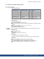
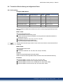
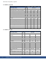
1.4.1 Package Supplied
Available MKD Modules
Variant Description Power Remarks
MKD-C003007-NAEC Central Power supply 30 kW Standard
MKD-N060007-DSEC Drive Module 2.5 kW Single Axis, 6A
MKD-N060607-DSEC Drive Module 5 kW Dual Axes, 2 x 6A
MKD-N120007-DSEC Drive Module 5 kW Single Axis, 12A
MKD-N120607-DSEC Drive Module 7.5 kW Dual Axes, 12A + 6A
MKD-N121207-DSEC Drive Module 10 kW Dual Axes, 2 x 12A
MKD-N240007-DSEC Drive Module 10 kW Single Axis, 24A
MKD-N480007-DSEC Drive Module 20 kW Single Axis, 48A
When a MKD module is ordered, the following items are included in the package:
MKD-C package:
The ordered module itself
Printed copy of MKD Product Safety Guide
DVD containing the setup software, WorkBench, and all product documentation in digital
format.
Mating connectors MKD-C: X12, X13, X14, X15, X16, X25
One MKD-N DC-Bus link cover
Two connector covers M23 for AKD-N
The M23 connector covers are required for protecting X2 of the last AKD-N in the strings.
MKD-N package:
The ordered module itself
Data Sheet
Mating connectors MKD-N: X9, X24, X26
Accessories:
Accessories must be ordered separately if required.
Accessories for AKD-N see regional Accessories Manual or AKD-N Installation Manual.
Spare parts
Connector Kit MKD-C-Conkit (X12, X13, X14, X15, X16, X25)
Connector Kit MKD-N-Conkit 6 to 12 A single (X9, X24, X26, X29A)
Connector Kit MKD-N-Conkit 6 to 12 A double (X9, X24, X26, X29A, X29B)
Connector Kit MKD-N-Conkit 24 to 48 A (X9, X24, X26, X29A, X30A)
MKD Product Safety Guide | 1 English
Kollmorgen | kdn.kollmorgen.com | January 2019 13

MKD Product Safety Guide | 1 English
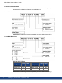
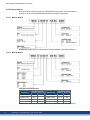
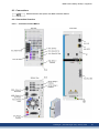
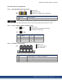
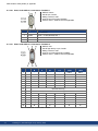
1.4.2 Part Number Scheme
Use the part number scheme for product identification only, not for the order process,
because not all combinations of features are possible, always.
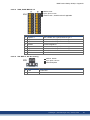
1.4.2.1 MKD-C modules
Customization code coding for customer specials (not relevant for functional safety).
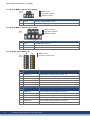
1.4.2.2 MKD-N modules
Available drive modules:
Current rating Current rating
Single Axis Axis 1 Axis 2 Dual Axes Axis 1 Axis 2
MKD-N0600 06 A - MKD-N0606 06 A 06 A
MKD-N1200 12 A - MKD-N1206 12 A 06 A
MKD-N2400 24 A - MKD-N1212 12 A 12 A
MKD-N4800 48 A -
Customization code coding for customer specials (not relevant for functional safety).
14 Kollmorgen | kdn.kollmorgen.com | January 2019

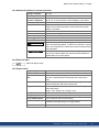
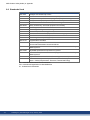
1.4.3 Ambient Conditions in normal operation
Storage, Transport (➜ # 10)
Normal operation Environmental class 3K3 according to IEC 61800-2
Surrounding air tem-
perature in operation
0 to +40 °C under rated conditions
+40 to +55 °C with continuous current derating 4 % per Kelvin
Humidity in operation Relative humidity 5 to 85%, no condensation, class 3K3
Site altitude Up to 1000 meters above mean sea level without restriction
1,000 to max. 2,000 meters above mean sea level with power
derating 1.5%/100 m
Pollution level Pollution level 2 as per IEC 60664-1
Vibrations Class 3M1 according to IEC 60721-3-3
Environmental area Cabinet IP 54 according to IEC 60529
Mounting position Vertical
Ventilation Built-in fan.
CAUTION
Continuous noise up to 60dBA during operation. Keep cabinet
doors closed during operation. To reduce inconvenience, we sug-
gest to use ear protection if cabinet doors must be opened during
normal operation.
The device shuts down in case of excessively high temperature
in the control cabinet. Make sure sufficient forced ventilation is
supplied within the control cabinet.
1.4.4 Electrical Data
Electrical data (➜ # 53)
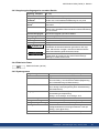
1.4.5 System limits
Length String 2/3 Maximum 100 m total cable length per string.
Number of MKD-C Limited by fieldbus protocol.
Number of MKD-N
axes
Maximum 14 axes for string 1, total maximum 28 axes if string 1
and 2 are combined (observe total power and current restric-
tions).
Number of AKD-N Maximum 14 per string, total maximum 28 on strings 2 and 3,
(observe total power and current restrictions).
Output current Use coincidence factor of the axes for distribution and system
power optimization.
String 1: 43 A, String 2: 16 A, String 3: 16 A
Total power At 565 V to 680 V limited to 30kW.
String 2/3 power At 565 V to 680 V limited to 10kW for each string.
String standby power At 55 V limited to 180W for each string.
Motor Brake power You can control up to 3 motor brakes per string. Available power
for brakes is 76 W per string (= 3.2 A @ 24 VDC).
Service Interface X18 Ethernet TCP/IP, 100 Mbit/s, max. cable distance 100m
MKD Product Safety Guide | 1 English
Kollmorgen | kdn.kollmorgen.com | January 2019 15

MKD Product Safety Guide | 1 English
1.5 Safe Torque Off (STO)
Safety functionality is not approved nor certified. Do not use this functionality in applications
with functional safety request.
Refer to the MKD Installation Manual for full information on functional safety.
The safety properties given by Kollmorgen listed in the appendix (➜ # 77) can be reached if
the Kollmorgen components are used. The resulting Functional Safety classification (SIL
and/or PL level) must be calculated across the drive system.
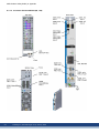
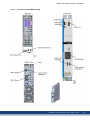
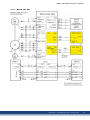
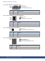
MKD-C connector X16:
global STO (String 2/3) inputs of the system powered by this MKD-C.
MKD-N connector X26:
local STO (axis 1 and axis 2 if built-in) input of the drive module.
AKD-N connectors X6:
local STO input of the AKD-N-DS/DT drive modules.
Global STO
There is one STO input for every DC Power string. The string STO input release the power
output stage of all AKD-N (without option DS/DT) connected to the string as long as a 24 V
signal is applied to this input.
Local STO
The local STO input releases the power output stage of the MKD-N drive axis as long as a 24
V signal is applied to this input.
16 Kollmorgen | kdn.kollmorgen.com | January 2019

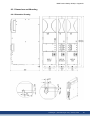
1.6 Mechanical Installation
Dimensions and mounting hints see (➜ # 55) and refer to the MKD Installation Manual.
1.6.1 Important Notes
MKD-C and MKD-N devices must be mounted in cabinets only with protection class IP 54
according to IEC 60529.
CAUTION
High EMC Voltage Level!
Risk of electrical shock, if the servo amplifier (or the motor) is not properly EMC-grounded.
Do not use painted (i.e. non-conductive) mounting plates.
In unfavourable circumstances, use copper mesh tape between the earthing bolts and
earth potential to deflect currents.
Protect the device from impermissible stresses. In particular, do not let any components
become bent or any insulation distances altered during transport and handling. Avoid con-
tact with electronic components and contacts.
The modules will switch itself off in case of overheating. Ensure that the mounting space
matches the requirements (➜ # 15).
Do not mount devices that produce magnetic fields directly beside the device. Strong mag-
netic fields can directly affect internal components. Install devices which produce magnetic
field with distance to the MKD-C and/or shield the magnetic fields.
1.6.2 Guide to Mechanical Installation
For details refer to the MKD Installation Manual.The following tools are required (at a min-
imum) to install the MKD-C and MKD-N modules; your specific installation may require addi-
tional tools.
M4 hexagon socket-cap screws (ISO 4762)
3 mm T-handle Allen key
No. 2 Phillips head screwdriver
Small slotted screwdriver
Install the modules as follows:
1. Prepare the site. The MKD modules must be mounted in a closed control cabinet (➜ #
15). The site must be free from conductive or corrosive materials.
2. Check that the ventilation of the modules is unimpeded, and keep within the permitted
ambient temperature (➜ # 15). Keep the required space clearance above and below the
modules (➜ # 56).
3. If cooling systems are used for the control cabinet, position the cooling system so that
condensation water cannot drip onto the modules or peripheral devices.
4. Assemble the power supply module and the drive modules on the conductive, grounded
mounting plate in the cabinet.
5. Ground the modules, the mounting plate, motor housing, GND of 24V supply and CNC-
GND of the control system.
For mechanical installation of AKD-N to the machine, refer to the AKD-N Installation
Manual.
MKD Product Safety Guide | 1 English
Kollmorgen | kdn.kollmorgen.com | January 2019 17

MKD Product Safety Guide | 1 English
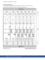
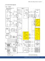
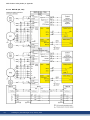
1.7 Electrical Installation
Connectors and Wiring overview see (➜ # 57) and refer to the MKD Installation Manual.
1.7.1 Important Notes
Only professional staff who are qualified in electrical engineering are allowed to install the
drive system. Wires with color green with one or more yellow stripes must not be used other
than for protective earth (PE) wiring.
DANGER
High Voltage up to 900 V!
There is a danger of serious personal injury or death by electrical shock or electrical arcing.
Capacitors can still have dangerous voltages present up to 5 minutes after switching off the
supply power. Control and power connections can still be live, even if the motor is not rotat-
ing.
Only install and wire the equipment when it is not live.
Make sure that the cabinet is safely disconnected (for instance, with a lock-out and warn-
ing signs).
Never remove electrical connections to the drive while it is live.
Wait at least 5 minutes after disconnecting the drive from the main supply power before
touching potentially live sections of the equipment (e.g. contacts) or undoing any con-
nections.
To be sure, measure the voltage in the DC bus link and wait until it has fallen below 50 V.
Since the leakage current to PE is more than 3.5 mA, in compliance with IEC61800-5-1 the
PE connection must either be doubled or a connecting cable with a cross-section >10 mm²
must be used. Deviating measures according to regional standards might be possible.
Wrong DC Bus link voltage, unsuitable motor or wrong wiring will damage the system com-
ponents. Check the combination of drive and motor. Compare the rated voltage and current
of the units. Implement the wiring according to the connection diagrams: (➜ # 57).
It is permissible to use the setup software to alter the settings of the device. Any other alter-
ations will invalidate the warranty.
1.7.2 Guide to electrical installation
For details refer to the MKD Installation Manual. Install the drive electrical system as follows:
1. Select cables accordance with the planned system topology, see (➜ # 15).
2. Observe the maximum cable length definition (➜ # 15).
3. Install shielding and ground the system components, see (➜ # 61).
4. Wire the system components.
- Observe "Recommendations for EMI noise reduction": see MKD Installation Manual
- Connect all interface according to the wiring diagrams in the MKD Installation Manual.
5. Check the wiring against the wiring diagrams in the MKD Installation Manual.
For electrical installation of AKD-N to the machine, refer to the AKD-N Installation Manual.
18 Kollmorgen | kdn.kollmorgen.com | January 2019

1.8 Setup
For detailed information on functional safety refer to the MKD Installation Manual.
Programming parameters and control loop behavior: see WorkBench online help.
The fieldbus setup is described in the corresponding manual on the DVD.
1.8.1 Important Notes
Before testing and setup, the manufacturer of the machine must generate a risk assessment
for the machine and take appropriate measures so that unforeseen movements cannot
cause injury or damage to any person or property.
Only professional personnel with extensive knowledge in the fields of electrical engineering
and drive technology are allowed to test and set up the drive.
DANGER
Lethal Voltage!
There is a danger of serious personal injury or death by electrical shock. Lethal danger exists
at live parts of the device.
Built-in protection measures such as insulation or shielding may not be removed.
Work on the electrical installation may only be performed by trained and qualified per-
sonnel, in compliance with the regulations for safety at work, and only with switched off
mains supply, and secured against restart.
WARNING
Automatic Restart!
Risk of death or serious injury for humans working in the machine. The drive might restart
automatically after power on, voltage dip or interruption of the supply voltage, depending on
the parameter setting. If parameter DRV.ENDEFAULT is set to 1,
then place a warning sign ("WARNING: Possible Automatic Restart" or similar) to the
machine.
Ensure, that power on is not possible, while humans are in a dangerous zone of the
machine.
CAUTION
High Temperature!
Risk of minor burns. The heat sink of the drive can reach temperatures up to 80°C in oper-
ation.
Check the heat sink temperature before handling the drive.
Wait until the heat sink has cooled down to 40°C before touching it.
If a device has been stored for more than 1 year, you must re-form the capacitors in the DC
bus link circuit. Re-forming procedures are described in the Kollmorgen Developer Network
(Forming).
MKD Product Safety Guide | 1 English
Kollmorgen | kdn.kollmorgen.com | January 2019 19

MKD Product Safety Guide | 1 English
1.8.2 Initial System Test
1. Unpack the devices and accessories. Observe the safety instructions in the doc-
umentation.
2. Mount the devices and wire the system.
3. Validate mechanical and electrical installation.
4. Validate IP addresses
5. Make sure you have on hand the following information about the drive components:
rated mains supply voltage
motor type (motor data, if the motor type is not listed in the motor database)
feedback unit built into the motor (type, poles/lines/protocol)
moment of inertia of the load
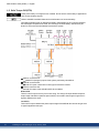
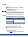
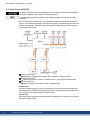
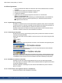
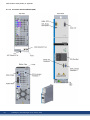
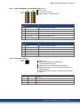
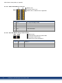
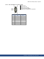
1.8.2.1 Set system addresses
The MKD-C IP address can be set with the rotary switch. When connecting the MKD-C dir-
ectly to a PC, static IP addressing (not 0) is recommended.
Example: if S1 is set to 5 – the IP address is 192.168.0.5
WorkBench looks for IP address in the subnet to detect devices in the LAN and start com-
munication. Refer to the WorkBench Online Help for information.
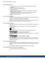
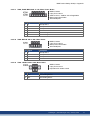
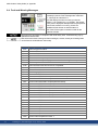
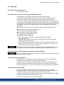
1.8.2.2 Confirm connections
Switch on 24 VDC logic power for the system (mains supply voltage is not needed for com-
munications).
Confirm that the green link LED 1 on the MKD-C and on the PC are both illuminated.
While the PC is connecting, your status bar will show the following acquiring icon:
Wait for this icon to change to the limited functionality icon (this process can take up to one
minute).
Although Windows displays this limited functionality icon for the drive connection, the PC
can communicate fully with the drive. Using WorkBench, you can now configure the drive
through this connection.
1.8.2.3 Install and start WorkBench
WorkBench is available from the DVD included with the drive and on the Kollmorgen Web-
site: www.kollmorgen.com. Select the install file and follow the instructions given by the
installer.
Once installation is complete, click the WorkBench icon to start the program.
1.8.2.4 Parameterize and enable the axes in WorkBench
Refer to the WorkBench Online Help for information.
20 Kollmorgen | kdn.kollmorgen.com | January 2019
Seite wird geladen ...
Seite wird geladen ...
Seite wird geladen ...
Seite wird geladen ...
Seite wird geladen ...
Seite wird geladen ...
Seite wird geladen ...
Seite wird geladen ...
Seite wird geladen ...
Seite wird geladen ...
Seite wird geladen ...
Seite wird geladen ...
Seite wird geladen ...
Seite wird geladen ...
Seite wird geladen ...
Seite wird geladen ...
Seite wird geladen ...
Seite wird geladen ...
Seite wird geladen ...
Seite wird geladen ...
Seite wird geladen ...
Seite wird geladen ...
Seite wird geladen ...
Seite wird geladen ...
Seite wird geladen ...
Seite wird geladen ...
Seite wird geladen ...
Seite wird geladen ...
Seite wird geladen ...
Seite wird geladen ...
Seite wird geladen ...
Seite wird geladen ...
Seite wird geladen ...
Seite wird geladen ...
Seite wird geladen ...
Seite wird geladen ...
Seite wird geladen ...
Seite wird geladen ...
Seite wird geladen ...
Seite wird geladen ...
Seite wird geladen ...
Seite wird geladen ...
Seite wird geladen ...
Seite wird geladen ...
Seite wird geladen ...
Seite wird geladen ...
Seite wird geladen ...
Seite wird geladen ...
Seite wird geladen ...
Seite wird geladen ...
Seite wird geladen ...
Seite wird geladen ...
Seite wird geladen ...
Seite wird geladen ...
Seite wird geladen ...
Seite wird geladen ...
Seite wird geladen ...
Seite wird geladen ...
Seite wird geladen ...
Seite wird geladen ...
-
 1
1
-
 2
2
-
 3
3
-
 4
4
-
 5
5
-
 6
6
-
 7
7
-
 8
8
-
 9
9
-
 10
10
-
 11
11
-
 12
12
-
 13
13
-
 14
14
-
 15
15
-
 16
16
-
 17
17
-
 18
18
-
 19
19
-
 20
20
-
 21
21
-
 22
22
-
 23
23
-
 24
24
-
 25
25
-
 26
26
-
 27
27
-
 28
28
-
 29
29
-
 30
30
-
 31
31
-
 32
32
-
 33
33
-
 34
34
-
 35
35
-
 36
36
-
 37
37
-
 38
38
-
 39
39
-
 40
40
-
 41
41
-
 42
42
-
 43
43
-
 44
44
-
 45
45
-
 46
46
-
 47
47
-
 48
48
-
 49
49
-
 50
50
-
 51
51
-
 52
52
-
 53
53
-
 54
54
-
 55
55
-
 56
56
-
 57
57
-
 58
58
-
 59
59
-
 60
60
-
 61
61
-
 62
62
-
 63
63
-
 64
64
-
 65
65
-
 66
66
-
 67
67
-
 68
68
-
 69
69
-
 70
70
-
 71
71
-
 72
72
-
 73
73
-
 74
74
-
 75
75
-
 76
76
-
 77
77
-
 78
78
-
 79
79
-
 80
80


Kollmorgen MKD-N240007 Product Safety Manual
- Typ
- Product Safety Manual
- Dieses Handbuch eignet sich auch für
in anderen Sprachen
- English: Kollmorgen MKD-N240007
Verwandte Artikel
-
Kollmorgen AKD2G-S**-6V03 Product Safety Manual
-
-
-
Kollmorgen AKM3 Benutzerhandbuch
-
-
Kollmorgen AKC-PCM-M Series Installationsanleitung
-
-
-
-
Kollmorgen C06 Benutzerhandbuch
Andere Dokumente
-
Baumer Heat Sink Type D Datenblatt
-
 Dryflow IFSM092A-ANON Series Benutzerhandbuch
-
Munters TDE-1071-D2001 Bedienungsanleitung
-
-
Pioneer GEX-P6400TVP Benutzerhandbuch
-
Renkforce HP-960S Bedienungsanleitung
-
-
-
-
Ametek dunkermotoren GR Series Translation Of The Original Assembly Instruction
