Master SM40 4inch E21 Bedienungsanleitung
- Typ
- Bedienungsanleitung

_______________________________________________________________________________________
_______________________________________________________________________________________
SM 4.0 – DISPLAY 4”
USER AND MAINTENANCE BOOK
en
INSIDE: en - it - de - es - fr - pl - ru

_______________________________________________________________________________________
_______________________________________________________________________________________
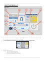
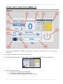
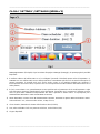
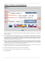
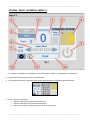
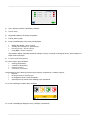
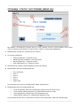
“MAIN” PAGE [MENU no.1]
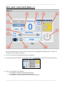
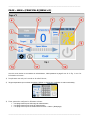
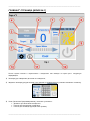
The hmi once powered and connected to the cooler, presents the screen in Pic.1 with the following information:
1) Temperature measured by the ntc probe of the cooler;
2) Target temperature (by touching the box, a keyboard appears for setting the desired value);
3) Timer, allows you to set:
• A band for turning on the cooler;
• A band for switching off the cooler;
• A band for activating the "clean" function.

_______________________________________________________________________________________
_______________________________________________________________________________________
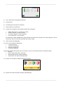
4) Auto, activates the set time slots;
5) Water level;
6) Fan rotation speed adjustment;
7) Measurement of current consumption;
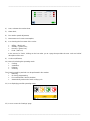
8) Icon showing the four states of the cooler:
• Offline - (black icon);
• Standby - (yellow icon);
• Running - (green icon);
• Fault - (red icon).
In the event of a "Fault", clicking on the icon takes you to a page that provides the error code and a brief
description of the error.
9) Cooler on/off button;
10) Menu for selecting the operating mode:
• Cooling;
• Ventilation;
• Exhaust;
• Cleaning.
The Cleaning mode in particular can be performed in four modes:
• Manually;
• On hourly programming;
• For reached limit "Clean Scheduler";
• Automatically at the end of each cooling cycle.
11) Icon displaying possible operating states;
12) Icon to access the "Settings" page.

_______________________________________________________________________________________
_______________________________________________________________________________________
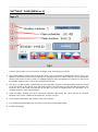
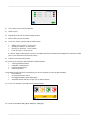
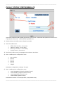
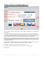
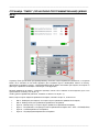
“SETTINGS” PAGE [MENU no.2]
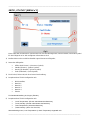
From the "Main" page you can access the "Settings" page, in this page you can set:
1) The modbus address of the cooler to which the panel is to be connected. By default this value is set to 1, the
address at which the coolers leave production, so normally there is no need to intervene on this parameter.
However, the panel can also be used on a multiple system to check the operation of a machine, in which case
the modbus address of the cooler to be controlled must be set;
2) The Clock, i.e. date and time, operationally you have to position yourself on the parameter you want to set and
act on the arrows on the right to reach the desired value. The panel does not show this but the system also
knows the day of the week corresponding to the date. The panel is equipped with RTC and buffer cap to
maintain the time in case of power failure;
3) Clean Scheduler, number of hours of continuous operation, after which the "clean" function is activated.
Minimum value 1 hour, maximum value 48 hours, in steps of 1 hour;
4) Clean duration, determines the duration of the clean function;
5) Aux, activates and deactivates the aux relays on the driver, output 230Vac/10A;
6) Available languages.

_______________________________________________________________________________________
_______________________________________________________________________________________
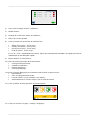
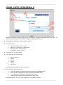
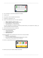
“STATUS” PAGE [MENU no.3]
Typically, the user only accesses this page in the event of an error, in which case the cooler icon is red. The
information available is:
1) Modbus Address of the cooler connected to the panel;
2) Status of the cooler:
• Offline - (black icon);
• Standby - (yellow icon);
• Running - (green icon);
• Fault - (red icon).
3) Fault Code accompanied by a short description;
4) Drop-down menu for configuration as:
• Not installed;
• Zone 1;
• Zone 2;
• Zone 3;
• Zone 4;
• Single.
The default configuration is "Single".
5) Drop-down menu for configuration as:
• "Local Temperature" (Single or Zone Master);
• "Local Humidity" (Single or Zone Master);
• "Area Temperature" (Zone Slave);
• "Areal Humidity" (Zone Slave).
The default must be “Local Temperature”.

_______________________________________________________________________________________
_______________________________________________________________________________________
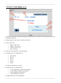
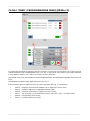
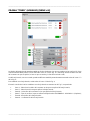
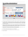
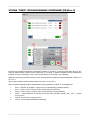
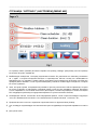
“TIMER” PAGE (TIME SCHEDULE) [MENU no.4]
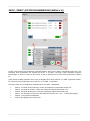
The timer page allows you to set time slots with which to associate a function. To create a band, press the icon
marked with No. 1 in Pic. 4. Each time slot shows the days of the week on which it applies, the time at which
it is activated and the function associated with it;
Each time slot, once created, can also be modified at a later date by clicking on icon no. 2 in Pic. 4;
To delete a time slot, click on icon No. 3 in Pic. 4;
The menu through which a time slot is set is shown in Pic. 5, in particular:
• Step 4 - Selection of days of the week on which the time slot is to be applied;
• Step 5 - Selection of the time at which the time slot is to be applied;
• Step 6 - Selection of the time slots to be applied;
• Step 7 - Type of action to which the time slot refers: ON – OFF – CLEAN;
• Step 8 - Cancellation of time slots;
• Step 9 - Confirmation of the time slot.

_______________________________________________________________________________________
_______________________________________________________________________________________
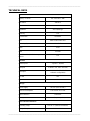
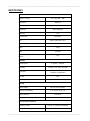
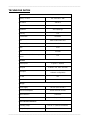
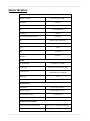
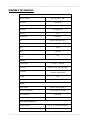
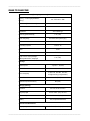
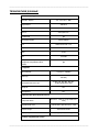
TECHNICAL DATA
System Resources
Display – Colours
4.3” TFT 16:9 – 64K
Resolution
480×272
Brightness
200 Cd/m2 typ.
Dimming
Yes
Touchscreen
Resistive
CPU
ARM Cortex A8 1 GHz
Operating System
Linux 3.12
Flash
4 GB
RAM
512 MB
Real Time Clock, RTC Back-up,
Buzzer
Yes
Interface
Ethernet port
1 (port 0 - 10/100)
USB port
1 (Host v. 2.0, max. 500 mA)
Serial port
1 (RS-232, RS-485, RS-422,
software configurable)
SD card
No
Expansion
No
Ratings
Power supply
24 Vdc (10 to 32 Vdc)
Current Consumption
0.25 A max. at 24 Vdc
Input Protection
Automatic
Battery
Yes (Supercapacitor)
Environment Conditions
Operating Temp
0 to 50 °C (vertical installation)
Storage Temp
-20°C to +70°C

_______________________________________________________________________________________
_______________________________________________________________________________________
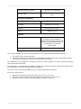
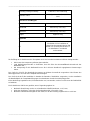
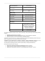
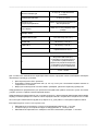
Operating / Storage Humidity
5-85% RH, non-condensing
Protection Class
IP66, Type 2 and 4X (front); IP20
(rear)
Dimensions and Weights
Faceplate LxH
147×107 mm (5.78×4.21“)
Cutout AxB
29+5 mm (1.14+0.19”)
Depth D+T
29+5 mm (1.14+0.19”)
Weight
Approx 0.4 Kg
Approvals
CE
Emission EN 61000-6-4, Immunity
EN 61000-6-2 for installation in
industrial environments Emission EN
61000-6-3, Immunity EN 61000-6-1
for installation in residential
environments
UL
cULus: UL508
The correct installation procedure must be followed to comply with front panel protection ratings:
• The edges of the cutout must be flat;
• Tighten each fixing screw until the corner of the plastic faceplate comes into contact with the panel;
• The cutout for the panel must be the size indicated in this manual.
The equipment is not intended for continuous exposure to direct sunlight. This may accelerate the ageing
process of the front panel film.
The equipment is not intended for installation in contact with corrosive chemicals. Check the resistance of the
front panel film to a specific compound before installation.
Do not use tools of any kind (screwdrivers, etc.) to operate the panel touchscreen.
IP66 is only guaranteed if:
• Maximum deviation from the surface plane to be cut out: <= 0.5 mm;
• Thickness of the housing in which the equipment is mounted: 1.5 mm to 6 mm;
• Maximum surface roughness where the gasket is applied: <=120 um.

_______________________________________________________________________________________
_______________________________________________________________________________________
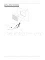
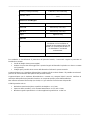
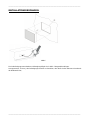
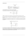
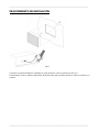
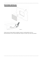
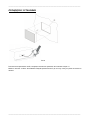
INSTALLATION PROCEDURE
Pic.6
Position the fixing brackets contained in the fixing kit as shown in Pic. 6.
Tightening torque: 75 Ncm. Tighten each fixing screw until the corner of the frame is in contact with the panel.

_______________________________________________________________________________________
_______________________________________________________________________________________
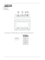
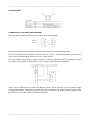
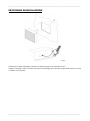
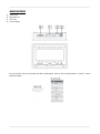
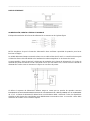
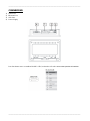
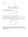
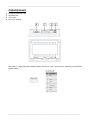
CONNECTIONS
1) Serial Port;
2) Ethernet Port;
3) USB Port;
4) Power Supply.
To operate with a 2-wire RS485 modbus, pins 4-3 and 8-7 must be jumpered externally.

_______________________________________________________________________________________
_______________________________________________________________________________________
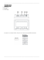
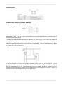
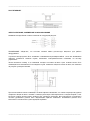
ETHERNET PORT
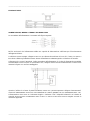
POWER SUPPLY, EARTHING AND SHIELDING
The terminal block of the power supply unit is shown in the following figure.
NOTE: Ensure that the power supply has sufficient power capacity to operate the equipment.
The unit must always be earthed with a minimum cable size of 1.5 sq. mm. Earthing helps to limit the effects
of noise due to electromagnetic interference on the control system.
Also earth terminal 3 on the power supply terminal block. The power supply circuit may be floating or earthed.
In the latter case, earth the common power source as shown in the figure with a dotted line.
When using the floating power scheme, note that the operator panels internally connect the power supply
common to earth with a 1 MΩ resistor in parallel with a 4.7 nF capacitor. The power supply must have double
or reinforced insulation. All electronic devices in the control system must be properly earthed. Earthing must
be carried out in accordance with the applicable regulations.

_______________________________________________________________________________________
_______________________________________________________________________________________
4250.294 Edition 21 Vers.

_______________________________________________________________________________________
_______________________________________________________________________________________
SM 4.0 – DISPLAY 4”
LIBRETTO USO E MANUTENZIONE
it

_______________________________________________________________________________________
_______________________________________________________________________________________
PAGINA “MAIN” (PRINCIPALE) [MENU n°1]
L’hmi una volta alimentato e collegato al raffrescatore, presenta la schermata di Fig.1 con le seguenti
informazioni:
1) Temperatura misurata dalla sonda ntc del raffrescatore;
2) Target temperatura (toccando il riquadro appare una tastiera per l’impostazione del valore desiderato);
3) Timer, permette di impostare:
• Una fascia per l’accensione del raffrescatore;
• Una fascia per lo spegnimento del raffrescatore;
• Una fascia per l’attivazione della funzione “clean” (Pulizia).

_______________________________________________________________________________________
_______________________________________________________________________________________
4) Auto, attiva le fasce orarie impostate;
5) Livello acqua;
6) Regolazione velocità di rotazione della ventola;
7) Misura della corrente assorbita;
8) Icona che mostra i quattro stati del raffrescatore:
• Offline (Fuori servizio) - (icona nera);
• Standby (In attesa) - (icona gialla);
• Running (In funzione) - (icona verde);
• Fault (In errore) - (icona rossa).
In caso di “Fault” (raffrescatore in errore), cliccando sull’icona si accede ad una pagina che fornisce il codice
errore e una breve descrizione dello stesso.
9) Pulsante on/off del raffrescatore;
10) Menu per la selezione della modalità di funzionamento:
• Cooling (Raffrescamento);
• Ventilation (Ventilazione);
• Exhaust (Aspirazione);
• Cleaning (Pulizia).
La modalità Cleaning (Pulizia) in particolare può essere eseguita secondo quattro modalità:
• Manualmente;
• Su programmazione oraria;
• Per raggiunto limite “Clean Scheduler”;
• Automaticamente alla fine di ogni ciclo di raffrescamento.
11) Icona che visualizza i possibili stati di funzionamento;
12) Icona per accedere alla pagina “Settings” (Settaggio).

_______________________________________________________________________________________
_______________________________________________________________________________________
PAGINA “SETTINGS” (SETTAGGIO) [MENU n°2]
Dalla pagina “Main” (Principale) si può accedere alla pagina “Settings” (Settaggio), in questa pagina è possibile
impostare:
1) Il modbus address del raffrescatore a cui va collegato il pannello. Di default questo valore è impostato a 1,
l’indirizzo con cui i raffrescatori escono dalla produzione, normalmente quindi non è necessario intervenire su
questo parametro. Il pannello però può anche essere usato su un impianto multiplo per verificare il
funzionamento di una macchina, in questo caso occorre impostare il modbus address del raffrescatore che si
vuole pilotare;
2) Il Clock, ovvero data e ora, operativamente occorre posizionarsi sul parametro che si vuole impostare e agire
sulle freccette a destra per raggiungere il valore desiderato. Il pannello non lo mostra ma il sistema conosce
anche il giorno della settimana corrispondente alla data. Il pannello è dotato di RTC e cap tampone per il
mantenimento dell’orario in caso di mancanza di corrente;
3) Clean Scheduler, numero di ore di funzionamento continuo, trascorse le quali si attiva la funzione “clean”.
Valore minimo 1 ora, valore massimo 48 ore, a step di 1 ora;
4) Clean duration, determina la durata della funzione clean (Pulizia);
5) Aux, attiva e disattiva i relè aux presente sul driver, uscita 230Vac/10A;
6) Lingue disponibili.

_______________________________________________________________________________________
_______________________________________________________________________________________
PAGINA “STATUS” (STATO) [MENU n°3]
Tipicamente l’utente accede a questa pagina solo in caso di errore, condizione nella quale l’icona raffrescatore
si presenta di colore rosso. Le informazioni disponibili sono:
1) Modbus Address del raffrescatore collegato al pannello;
2) Status del raffrescatore:
• Offline (Fuori servizio) - (icona nera);
• Standby (In attesa) - (icona gialla);
• Running (In funzione) - (icona verde);
• Fault (In errore) - (icona rossa).
3) Fault Code (Codice errore) accompagnato da una breve descrizione;
4) Menu a tendina per la configurazione come:
• Non Installato;
• Zona 1;
• Zona 2;
• Zona 3;
• Zona 4;
• Singolo.
Di default la configurazione è “Single” (Singolo).
5) Menu a tendina per la configurazione come:
• “Local Temperature” (Singola o Master di zona);
• “Local Humidity” (Singola o Master di zona);
• “Area Temperature” (Slave di zona);
• “Areal Humidity” (Slave di zona).
Di default deve essere “Local Temperature” (Temperatura locale).

_______________________________________________________________________________________
_______________________________________________________________________________________
PAGINA “TIMER” (PROGRAMMAZIONE ORARI) [MENU n°4]
La pagina timer permette di impostare delle fasce orarie a cui associare una funzione. Per creare una fascia
si deve premere l’icona contrassegnata con il n°1 in Fig. 4. Ogni fascia oraria mostra i giorni della settimana
in cui si applica, l’orario in cui si attiva e la funzione ad essa associata;
Ogni fascia oraria, una volta creata può essere modificata anche successivamente agendo sull’icona n°2 in
Fig. 4;
Per eliminare una fascia oraria, agire sull’icona n°3 in Fig. 4;
Il menu tramite il quale si imposta una fascia oraria è mostrato nella Fig. 5, in particolare:
• Punto 4 – Selezione dei giorni della settimana in cui applicare la fascia oraria;
• Punto 5 – Selezione dell’ora in cui applicare la fascia oraria;
• Punto 6 – Selezione dei muniti in cui applicare la fascia oraria;
• Punto 7 – Tipo di azione a cui fa riferimento la fascia oraria: ON – OFF – CLEAN (Pulizia);
• Punto 8 – Cancellazione fascia oraria;
• Punto 9 – Conferma della fascia oraria.

_______________________________________________________________________________________
_______________________________________________________________________________________
DATI TECNICI
System Resources
Display – Colors
4.3” TFT 16:9 – 64K
Resolution
480×272
Brightness
200 Cd/m2 typ.
Dimming
Yes
Touchscreen
Resistive
CPU
ARM Cortex A8 1 GHz
Operating System
Linux 3.12
Flash
4 GB
RAM
512 MB
Real Time Clock, RTC Back-up,
Buzzer
Yes
Interface
Ethernet port
1 (port 0 – 10/100)
USB port
1 (Host v. 2.0, max. 500 mA)
Serial port
1 (RS-232, RS-485, RS-422,
software configurable)
SD card
No
Expansion
No
Ratings
Power supply
24 Vdc (10 to 32 Vdc)
Current Consumption
0.25 A max. at 24 Vdc
Input Protection
Automatic
Battery
Yes (Supercapacitor)
Environment Conditions
Operating Temp
0 to 50 °C (vertical installation)
Storage Temp
-20°C to +70°C

_______________________________________________________________________________________
_______________________________________________________________________________________
Operating / Storage Humidity
5-85% RH, non condensing
Protection Class
IP66, Type 2 and 4X (front); IP20
(rear)
Dimensions and Weights
Faceplate LxH
147×107 mm (5.78×4.21“)
Cutout AxB
29+5 mm (1.14+0.19”)
Depth D+T
29+5 mm (1.14+0.19”)
Weight
Approx 0.4 Kg
Approvals
CE
Emission EN 61000-6-4, Immunity
EN 61000-6-2 for installation in
industrial environments Emission EN
61000-6-3, Immunity EN 61000-6-1
for installation in residential
environments
UL
cULus: UL508
Per soddisfare le classificazioni di protezione del pannello frontale, è necessario seguire la procedura di
installazione corretta:
• I bordi del ritaglio devono essere piatti;
• Avvitare ciascuna vite di fissaggio fino a quando l'angolo del frontalino in plastica non viene a contatto
con il pannello;
• Il ritaglio per il pannello deve essere delle dimensioni indicate in questo manuale.
L'apparecchiatura non è destinata all'esposizione continua alla luce solare diretta. Ciò potrebbe accelerare il
processo di invecchiamento della pellicola del pannello frontale.
L'apparecchiatura non è destinata all'installazione a contatto con composti chimici corrosivi. Verificare la
resistenza della pellicola del pannello frontale a un composto specifico prima dell'installazione.
Non utilizzare strumenti di alcun tipo (cacciaviti, ecc.) per azionare il touchscreen del pannello.
L'IP66 è garantito solo se:
• Deviazione massima dal piano superficie da ritagliare: <= 0,5 mm;
• Spessore della custodia in cui è montata l'attrezzatura: da 1,5 mm a 6 mm;
• Massima rugosità superficiale in cui viene applicata la guarnizione: <=120 um.
Seite wird geladen ...
Seite wird geladen ...
Seite wird geladen ...
Seite wird geladen ...
Seite wird geladen ...
Seite wird geladen ...
Seite wird geladen ...
Seite wird geladen ...
Seite wird geladen ...
Seite wird geladen ...
Seite wird geladen ...
Seite wird geladen ...
Seite wird geladen ...
Seite wird geladen ...
Seite wird geladen ...
Seite wird geladen ...
Seite wird geladen ...
Seite wird geladen ...
Seite wird geladen ...
Seite wird geladen ...
Seite wird geladen ...
Seite wird geladen ...
Seite wird geladen ...
Seite wird geladen ...
Seite wird geladen ...
Seite wird geladen ...
Seite wird geladen ...
Seite wird geladen ...
Seite wird geladen ...
Seite wird geladen ...
Seite wird geladen ...
Seite wird geladen ...
Seite wird geladen ...
Seite wird geladen ...
Seite wird geladen ...
Seite wird geladen ...
Seite wird geladen ...
Seite wird geladen ...
Seite wird geladen ...
Seite wird geladen ...
Seite wird geladen ...
Seite wird geladen ...
Seite wird geladen ...
Seite wird geladen ...
Seite wird geladen ...
Seite wird geladen ...
Seite wird geladen ...
Seite wird geladen ...
Seite wird geladen ...
Seite wird geladen ...
Seite wird geladen ...
Seite wird geladen ...
Seite wird geladen ...
Seite wird geladen ...
Seite wird geladen ...
Seite wird geladen ...
Seite wird geladen ...
Seite wird geladen ...
Seite wird geladen ...
Seite wird geladen ...
Seite wird geladen ...
Seite wird geladen ...
Seite wird geladen ...
Seite wird geladen ...
-
 1
1
-
 2
2
-
 3
3
-
 4
4
-
 5
5
-
 6
6
-
 7
7
-
 8
8
-
 9
9
-
 10
10
-
 11
11
-
 12
12
-
 13
13
-
 14
14
-
 15
15
-
 16
16
-
 17
17
-
 18
18
-
 19
19
-
 20
20
-
 21
21
-
 22
22
-
 23
23
-
 24
24
-
 25
25
-
 26
26
-
 27
27
-
 28
28
-
 29
29
-
 30
30
-
 31
31
-
 32
32
-
 33
33
-
 34
34
-
 35
35
-
 36
36
-
 37
37
-
 38
38
-
 39
39
-
 40
40
-
 41
41
-
 42
42
-
 43
43
-
 44
44
-
 45
45
-
 46
46
-
 47
47
-
 48
48
-
 49
49
-
 50
50
-
 51
51
-
 52
52
-
 53
53
-
 54
54
-
 55
55
-
 56
56
-
 57
57
-
 58
58
-
 59
59
-
 60
60
-
 61
61
-
 62
62
-
 63
63
-
 64
64
-
 65
65
-
 66
66
-
 67
67
-
 68
68
-
 69
69
-
 70
70
-
 71
71
-
 72
72
-
 73
73
-
 74
74
-
 75
75
-
 76
76
-
 77
77
-
 78
78
-
 79
79
-
 80
80
-
 81
81
-
 82
82
-
 83
83
-
 84
84


Master SM40 4inch E21 Bedienungsanleitung
- Typ
- Bedienungsanleitung
in anderen Sprachen
Verwandte Artikel
-
Master SM40 10inch E21 Bedienungsanleitung
-
Master SM 4.0 Benutzerhandbuch
-
-
Master BCF230 4140.377 R19E2 Bedienungsanleitung
-
-
-
-