
Operating instructions
Betriebsanleitung
EN
DE
full assessment
SIL 2
Temperature transmitter, model T32.xS
Temperaturtransmitter, Typ T32.xS
Head mounting version
model T32.1S
Rail mounting version
model T32.3S

EN
DE
2
11258421.16 10/2018 EN/DE
WIKA operating instructions model T32.xS
Operating instructions model T32.xS
Page
3 - 38
Betriebsanleitung Typ T32.xS
Seite
39 - 78
Further languages can be found at www.wika.com.
© 05/2010 WIKA Alexander Wiegand SE & Co. KG
All rights reserved. / Alle Rechte vorbehalten.
WIKA
®
is a registered trademark in various countries.
WIKA
®
ist eine geschützte Marke in verschiedenen Ländern.
Prior to starting any work, read the operating instructions!
Keep for later use!
Vor Beginn aller Arbeiten Betriebsanleitung lesen!
Zum späteren Gebrauch aufbewahren!

EN
11258421.16 10/2018 EN/DE
WIKA operating instructions model T32.xS 3
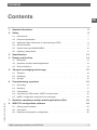
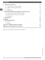
Contents
Contents
1. General information 5
2. Safety 6
2.1 Intended use . . . . . . . . . . . . . . . . . . . . . . . . . 7
2.2 Personnel qualification . . . . . . . . . . . . . . . . . . . . . . 7
2.3 Additional safety instructions for instruments per ATEX . . . . . . . . . . . 8
2.4 Special hazards . . . . . . . . . . . . . . . . . . . . . . . . 8
2.5 Version history per NAMUR NE53 . . . . . . . . . . . . . . . . . . 10
2.6 Labelling, safety labels . . . . . . . . . . . . . . . . . . . . . . 11
3. Specications 13
4. Design and function 14
4.1 Description . . . . . . . . . . . . . . . . . . . . . . . . . . 14
4.2 Operation in safety-related applications . . . . . . . . . . . . . . . . 14
4.3 Scope of delivery . . . . . . . . . . . . . . . . . . . . . . . . 14
5. Transport, packaging and storage 15
5.1 Transport . . . . . . . . . . . . . . . . . . . . . . . . . . . 15
5.2 Packaging . . . . . . . . . . . . . . . . . . . . . . . . . . 15
5.3 Storage . . . . . . . . . . . . . . . . . . . . . . . . . . . 15
6. Commissioning, operation 16
6.1 Grounding . . . . . . . . . . . . . . . . . . . . . . . . . . 16
6.2 Mounting . . . . . . . . . . . . . . . . . . . . . . . . . . . 17
6.3 Configuration . . . . . . . . . . . . . . . . . . . . . . . . . 19
6.4 Connection of FSK modem, HART
®
communicator . . . . . . . . . . . . 21
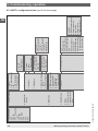
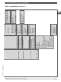
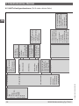
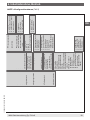
6.5 HART
®
configuration tree (part 2 see next page) . . . . . . . . . . . . . 22
7. Notes for operating in safety-related applications (SIL) 24
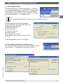
8. WIKAT32congurationsoftware 24
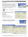
8.1 Starting up the software . . . . . . . . . . . . . . . . . . . . . . 24
8.2 Connection . . . . . . . . . . . . . . . . . . . . . . . . . . 25
8.3 Parameter configuration (configurable). . . . . . . . . . . . . . . . . 25

EN
11258421.16 10/2018 EN/DE
WIKA operating instructions model T32.xS4
9. Electrical connections 27
9.1 Power supply, 4 ... 20 mA current loop . . . . . . . . . . . . . . . . . 28
9.2 HART
®
loop display (DIH50, DIH52) . . . . . . . . . . . . . . . . . 29
9.3 Sensors . . . . . . . . . . . . . . . . . . . . . . . . . . . 29
9.4 HART
®
signal . . . . . . . . . . . . . . . . . . . . . . . . . 30
10. Notes for mounting and operating in hazardous areas 31
10.1 Model overview and their European approvals . . . . . . . . . . . . . . 32
10.2 Special conditions for safe use (X conditions) . . . . . . . . . . . . . . 32
10.3 Safety values . . . . . . . . . . . . . . . . . . . . . . . . . 35
11. Maintenance 36
12. Faults 37
13. Return and disposal 38
13.1 Return. . . . . . . . . . . . . . . . . . . . . . . . . . . . 38
13.2 Disposal . . . . . . . . . . . . . . . . . . . . . . . . . . . 38
Appendix 1: FM/CSA Installation drawing 74
Appendix 2: EU declaration of conformity 78
Declarations of conformity can be found online at www.wika.com.
Contents

EN
11258421.16 10/2018 EN/DE
WIKA operating instructions model T32.xS 5
1. General information
■
The temperature transmitter described in the operating instructions has been designed
and manufactured using state-of-the-art technology. All components are subject
to stringent quality and environmental criteria during production. Our management
systems are certified to ISO 9001 and ISO 14001.
■
These operating instructions contain important information on handling the instrument.
Working safely requires that all safety instructions and work instructions are observed.
■
Observe the local accident prevention regulations and general safety regulations, in
effect for the instrument's range of use.
■
The operating instructions are part of the instrument and must be kept in the immediate
vicinity of the instrument and readily accessible to skilled personnel at any time.
■
Skilled personnel must have carefully read and understood the operating instructions,
prior to beginning any work.
■
The manufacturers liability is void in the case of any damage caused by using the
product contrary to its intended use, non-compliance with these operating instructions,
assignment of insufficiently qualified skilled personnel or unauthorised modifications to
the instrument.
■
The general terms and conditions, contained in the sales documentation, shall apply.
■
Subject to technical modifications.
■
Further information:
- Internet address: www.wika.de / www.wika.com
- Relevant data sheet: TE 32.04
- Application consultant: Tel.: +49 9372 132-0
Fax: +49 9372 132-406
info@wika.com
Explanation of symbols
WARNING!
... indicates a potentially dangerous situation, which can result in serious
injury or death, if not avoided.
CAUTION!
... indicates a potentially dangerous situation, which can result in light injuries
or damage to equipment or the environment, if not avoided.
1. General information

EN
11258421.16 10/2018 EN/DE
WIKA operating instructions model T32.xS6
Information
... points out useful tips, recommendations and information for efficient and
trouble-free operation.
DANGER!
... identifies hazards caused by electrical power. Should the safety instructions
not be observed, there is a risk of serious or fatal injury.
WARNING!
... indicates a potentially dangerous situation hazardous area that can result in
serious injury or death, if not avoided.
2. Safety
WARNING!
Before installation, commissioning and operation, ensure that the appropriate
temperature transmitter has been selected in terms of measuring range,
design and specific measuring conditions.
Non-observance can result in serious injury and/or damage to the equipment.
WARNING!
This is Protection Class 3 equipment for connection at low voltages,
which are separated from the power supply or voltage by greater than
AC 50 V or DC 120 V. Preferably, a connection to an SELV or PELV circuit
is recommended; alternatively protective measures from HD 60346-4-41
(DIN VDE 0100-410).
Alternatively for North America:
The connection can be made in line with “Class 2 Circuits” or “Class 2 Power
Units” in accordance with CEC (Canadian Electrical Code) or NEC (National
Electrical Code)
Further important safety instructions can be found in the individual chapters of
these operating instructions.
1. General information / 2. Safety

EN
11258421.16 10/2018 EN/DE
WIKA operating instructions model T32.xS 7
2.1 Intended use
The model T32.xS temperature transmitter is a universal transmitter, configurable via
HART
®
protocol, for use with resistance thermometers (RTD), thermocouples (TC),
resistance and voltage sources as well as potentiometers.
The instrument has been designed and built solely for the intended use described here,
and may only be used accordingly.
The technical specifications contained in these operating instructions must be observed.
Improper handling or operation of the instrument outside of its technical specifications
requires the instrument to be taken out of service immediately and inspected by an
authorised WIKA service engineer.
If the instrument is transported from a cold into a warm environment, the formation
of condensation may result in the instrument malfunction. Before putting it back into
operation, wait for the instrument temperature and the room temperature to equalise.
The manufacturer shall not be liable for claims of any type based on operation contrary to
the intended use.
2.2 Personnel qualification
WARNING!
Risk of injury should qualification be insufficient!
Improper handling can result in considerable injury to personnel and damage
to equipment.
■
The activities described in these operating instructions may only be carried
out by skilled personnel who have the qualifications described below.
■
Keep unqualified personnel away from hazardous areas.
Skilled personnel
Skilled personnel are understood to be personnel who, based on their technical training,
knowledge of measurement and control technology and on their experience and
knowledge of country-specific regulations, current standards and directives, are capable of
carrying out the work described and independently recognising potential hazards.
Special operating conditions require further appropriate knowledge, e.g. of aggressive
media.
2. Safety

EN
11258421.16 10/2018 EN/DE
WIKA operating instructions model T32.xS8
2.3 Additional safety instructions for instruments per ATEX
WARNING!
Non-observance of these instructions and their contents may result in the loss
of explosion protection.
WARNING!
■
Observe the applicable regulations for the use of Ex-class instruments
■
Do not use transmitters with any damage to the exterior!
2.4 Special hazards
WARNING!
Observe the information given in the applicable type examination certificate
and the relevant country-specific regulations for installation and use in
hazardous areas (e.g. IEC 60079-14, NEC, CEC). Non-observance can result
in serious injury and/or damage to equipment.
For additional important safety instructions for instruments with ATEX
approval see chapter 2.3 “Additional safety instructions for instruments per
ATEX”.
WARNING!
The functional galvanic isolation present in the instrument does not ensure
sufficient protection against electrical impulses in the sense of EN 61140.
WARNING!
For hazardous media such as oxygen, acetylene, flammable or toxic gases or
liquids, and refrigeration plants, compressors, etc., in addition to all standard
regulations, the appropriate existing codes or regulations must also be
followed.
WARNING!
To ensure safe working on the instrument, the operator must ensure
■
that suitable first-aid equipment is available and aid is provided whenever
required.
■
that the operating personnel are regularly instructed in all topics regarding
work safety, first aid and environmental protection and know the operating
instructions and, in particular, the safety instructions contained therein.
2. Safety

EN
11258421.16 10/2018 EN/DE
WIKA operating instructions model T32.xS 9
WARNING!
When working during a running process operation, measures to prevent
electrostatic discharge from the connecting terminals should be taken, as a
discharge could lead to temporary corruption of the measured value.
The model T32.1S temperature transmitter should only be used with
grounded thermometers! The connection of a resistance thermometer (e.g.
Pt100) to the T32.3S must be made with shielded cable. The shield must
be electrically connected with the housing of the grounded thermometer.
(drawings see chapter 6.1 “Grounding”)
The connection of a thermocouple sensor to the T32.3S must be made
with a screened cable. The shield must be electrically connected with the
housing of the grounded thermometer and, additionally, grounded to the
side of the T32.3S. It should be ensured that there is equipotential bonding
on installation, so that no balancing current can flow via the shield. Here, in
particular, the installation regulations for hazardous areas should be followed!
The enclosure is constructed from plastic. To prevent the risk of electrostatic
sparking the plastic surface should be cleaned only with a damp cloth.
DANGER!
Danger of death caused by electric current
Upon contact with live parts, there is a direct danger of death.
■
The instrument may only be installed and mounted by skilled personnel.
■
Operation using a defective power supply unit (e.g. short circuit from the
mains voltage to the output voltage) can result in life-threatening voltages
at the instrument!
WARNING!
Only instruments as described in chapter 4.2 “Operation in safety-related
applications” are qualified for use in safety-related applications. Do not use
other instruments in safety or Emergency Stop devices.
Incorrect use of the instrument can result in injury.
2. Safety

EN
11258421.16 10/2018 EN/DE
WIKA operating instructions model T32.xS10
2. Safety
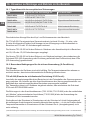
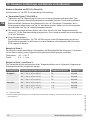
2.5 Version history per NAMUR NE53
2.5.1 HART
®
5 instruments
Version Notes Configuration
WIKA_T32
software
T32 HART
®
instrument
revision
Corresponding
DD (Device
Description)
v2.1.3 first T32.xS version v1.50 3 Dev v3, DD v1
v2.2.1
1)
T32.xS version with SIL
option
v1.51 3 Dev v3, DD v1
v2.2.3
1)
T32.xS (Change
Notification Q2/2014)
v1.51 3 Dev v3, DD v1
1) For instruments without SIL a restart of the transmitter after enabling the “write protection” is recommended.
2.5.2 Option: HART
®
7 instruments
Version Notes Configuration
WIKA_T32
software
T32 HART
®
instrument
revision
Corresponding
DD (Device
Description)
v2.3.1 Optional
HART
®
7 version
v1.51 4 Dev v3, DD v1

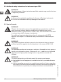
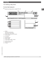
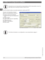
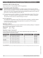
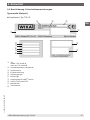
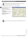
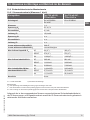
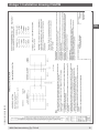
Model
with SIL: T32.1S.0IS-S
without SIL: T32.1S.0IS-Z
Date of manufacture (year-month)
Serial number
Ex marking
Approval logos
Power supply
Output signal, HART
®
version
Sensor, Pt100 or RTD
Measuring range
TAG no.
EN
11258421.16 10/2018 EN/DE
WIKA operating instructions model T32.xS 11
2.6 Labelling, safety labels
Product label (example)
■
Head mounting version, model T32.1S
2. Safety

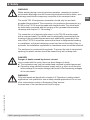
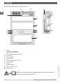
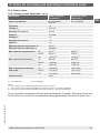
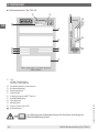
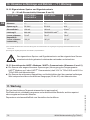
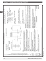
Model
with SIL: T32.3S.0IS-S
without SIL: T32.3S.0IS-Z
Date of manufacture (year-month)
Ex marking
Approval logos
Power supply
Output signal, HART
®
version
Pin assignment
TAG no.
Measuring range
Sensor, Pt100 or RTD
Serial number
Before mounting and commissioning the instrument, ensure you
read the operating instructions!
11
11
11
EN
11258421.16 10/2018 EN/DE
WIKA operating instructions model T32.xS12
■
Rail mounting version, model T32.3S
2. Safety

EN
11258421.16 10/2018 EN/DE
WIKA operating instructions model T32.xS 13
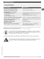
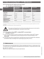
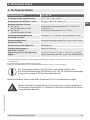
3. Specifications
Specifications Model T32.xS
Permissible ambient temperature -60
1)
/ -50
2)
/ -40 ... +85 °C
Climate class per IEC 654-1: 1993 Cx (-40 ... +85 °C, 5 ... 95 % r. h.)
Maximum permissible humidity
■
Model T32.1S
per IEC 60068-2-38: 1974
■
Model T32.3S
per IEC 60068-2-30: 2005
Test max. temperature variation 65 °C and -10 °C,
r. h. 93 % ±3 %
Test max. temperature 55 °C, r. h. 95 %
Vibration resistance per IEC 60068-2-6:2007 Test Fc: 10 ... 2,000 Hz; 10 g, Amplitude 0.75 mm
Shock resistance per IEC 68-2-27: 1987 Test Ea: Acceleration Type I 30 g and Type II 100 g
Salt fog per IEC 60068-2-52 Severity level 1
Freefall in accordance with
IEC 60721-3-2: 1997
Drop height 1,500 mm
Electromagnetic compatibility (EMC)
3)
EN 61326 Emission (Group 1, Class B) and
immunity (industrial application)
1) Special version on request (only available with specific approvals), not for rail mounting version T32.3S, not for SIL version
2) Special version, not for rail mounting version T32.3S
3) During interference an increased measuring deviation of up to 1 % has to be considered.
The model T32.1R temperature transmitter is available on request. The EU
declaration of conformity (ATEX/EMC) is valid without restrictions for T32.1R
(see “Appendix 2: EU declaration of conformity”).
For further specifications see WIKA data sheet TE 32.04 and the order documentation.
For further important safety instructions for operation in hazardous areas see
chapter 10 “Notes for mounting and operating in hazardous areas”.
3. Specifications

EN
11258421.16 10/2018 EN/DE
WIKA operating instructions model T32.xS14
4. Design and function
4.1 Description
The temperature transmitter is used for converting a resistance value or a voltage value
into a proportional current signal (4 ... 20 mA).
Thus the sensors are permanently monitored for their fault-free operation.
The transmitter meets the requirements for:
■
Functional safety per IEC 61508 / IEC 61511-1 (depending on the version)
■
Explosion protection (depending on the version)
■
Electromagnetic compatibility in accordance with NAMUR recommendation NE21
■
Signalling at the analogue output in accordance with NAMUR recommendation NE43
■
Sensor burnout signalling in accordance with NAMUR recommendation NE89
(corrosion monitoring sensor connection)
4.2 Operation in safety-related applications
The model T32.xS.xxx-S (SIL version) has been designed for use in safety-
related applications.
The marking of this design variant is given in chapter 2.6 “Labelling, safety marking”. For
operation in safety-related applications the additional requirements must be observed
(see safety manual “Information on functional safety of model T32.xS”). The instructions
contained in this must be followed without fail.
4.3 Scope of delivery
Cross-check scope of delivery with delivery note.
4. Design and function

EN
11258421.16 10/2018 EN/DE
WIKA operating instructions model T32.xS 15
5. Transport, packaging and storage
5.1 Transport
Check instrument for any damage that may have been caused by transport. Obvious
damage must be reported immediately.
5.2 Packaging
Do not remove packaging until just before mounting.
Keep the packaging as it will provide optimum protection during transport (e.g. change in
installation site, sending for repair).
5.3 Storage
Permissible conditions at the place of storage:
■
Storage temperature: -40 ... +85 °C
■
Humidity: 95 % relative humidity
Avoid exposure to the following factors:
■
Direct sunlight or proximity to hot objects
■
Mechanical vibration
■
Soot, vapour, dust and corrosive gases
5. Transport, packaging and storage

EN
11258421.16 10/2018 EN/DE
WIKA operating instructions model T32.xS16
6. Commissioning, operation
In hazardous areas, only use temperature transmitters that are approved for
those hazardous areas. The approval is marked on the product label.
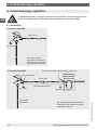
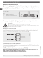
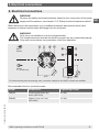
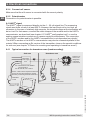
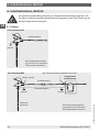
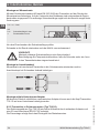
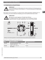
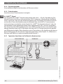
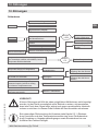
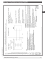
6.1 Grounding
Connection head BSZ
grounded
Loop circuit
The model T32.1S
temperature transmitter
should only be used with
grounded thermometers!
grounded
grounded shield
Thermowell
with sensor
grounded
sensor wire
equipotential bonding
T32.xS
Field housing/
switch cabinet
For thermocouples, additionally ground here!
For grounding of the model T32.xS
temperature transmitter see safety
instructions page 7f.
Connection head BSZ
6. Commissioning, operation

EN
11258421.16 10/2018 EN/DE
WIKA operating instructions model T32.xS 17
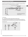
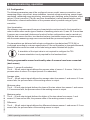
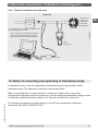
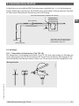
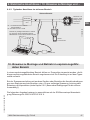
For applications with higher EMC requirements, it is recommended using a shielded cable
between the temperature transmitter and the sensor, especially in connection with long
leads to the sensor. For an exemplary illustration, see drawing.
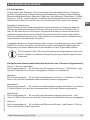
6.2 Mounting
6.2.1 Transmitter in head mounting version (model T32.1S)
The transmitters for head mounting (model T32.1S) are designed to be mounted on a
measuring insert within a Form B, DIN connection head, with extended mounting space.
The connection wires of the measuring insert must be approx. 50 mm long and insulated.
grounded
grounded shield
sensor wire
equipotential bonding
T32.xS
Field housing/
switch cabinet
For thermocouples, additionally ground here!
sensor
For grounding of the model T32.xS
temperature transmitter see safety
instructions page 7f.
Mounting example:
3173801.A
6. Commissioning, operation

EN
11258421.16 10/2018 EN/DE
WIKA operating instructions model T32.xS18
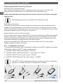
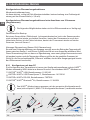
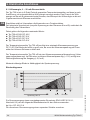
Mounting on the measuring insert
Mount the transmitter on the circular plate of the measuring insert using two countersunk
M3 screws per EN ISO 2009. Appropriate threaded inserts have been press-fitted in the
underside of the case. Assuming the countersinking is carried out correctly, the permissible
screw length can be calculated as follows:
Check the screw length before fixing the transmitter to the measuring insert: insert the
screw into the circular plate and verify length of 4 mm!
CAUTION!
Do not exceed the maximum permissible screw length!
The transmitter will be damaged if the screws are screwed further than 4 mm
into the bottom of the transmitter.
Mounting in connection head
Insert the measuring insert with the mounted transmitter into the protective sheath and
secure into the connecting head using screws in pressure springs.
Installation by means of DIN rail adapter
If the mechanical adapter, available as an accessory, is used the T32.1S head transmitters
can also be fixed on a DIN rail.
6.2.2 Transmitter in rail mounting version (model T32.3S)
Fasten the rail mounting case (model T32.3S) onto a 35 mm top-hat rail (EN 60715) by
simply locking it into place without the need for any tools.
Disassembly is achieved by unlocking the locking element.
l
max
= s + 4 mm
with
l
max
Length of screw in mm
s Thickness of circular plate in mm
3173801.B
max. 4
Circular plate
l
s
3173801.C
6. Commissioning, operation

EN
11258421.16 10/2018 EN/DE
WIKA operating instructions model T32.xS 19
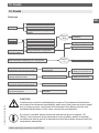
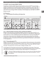
6.3 Configuration
The following parameters can all be configured: sensor model, sensor connection, user
measuring range, output limit, alarm indication, terminal voltage monitoring, sensor break
monitoring, measuring range monitoring, measuring rate, damping, write protection, offset
values (1-point correction), Tag No. and user linearisation (custom chararcteristic curve).
Furthermore, a linear transformation of the process value is possible using a 2-point
correction.
User linearisation:
Via software, customer-specific sensor characteristics can be stored in the transmitter in
order to define other sensor types. Number of auxiliary points: min. 2; max. 30. If more than
2 sensors are connected (dual sensor function) further configurations can be carried out.
With the dual sensor function, two identical sensors (resistance sensor or thermocouple)
with the same measuring range are connected and then processed together.
The transmitters are delivered with a basic configuration (see data sheet TE 32.04) or
configured according to customer specifications. If the configuration is changed afterwards,
the modifications must be noted on the label using a water-resistant felt-tip pen.
A simulation of the input value is not required to configure the T32.
A sensor simulation is only required for the functional test.
Freely programmable sensor functionality when 2 sensors have been connected
(dual sensor)
Sensor 1, sensor 2 redundant:
The 4 … 20 mA output signal delivers the process value of sensor 1. If sensor 1 fails, the
process value of sensor 2 is output (sensor 2 is redundant).
Average value:
The 4 … 20 mA output signal delivers the average value from sensor 1 and sensor 2. If one
sensor fails, the process value of the working sensor is output.
Minimum value:
The 4 ... 20 mA output signal delivers the lower of the two values from sensor 1 and sensor
2. If one sensor fails, the process value of the working sensor is output.
Maximum value:
The 4 ... 20 mA output signal delivers the higher of the two values from sensor 1 and
sensor 2. If one sensor fails, the process value of the working sensor is output.
Difference:
The 4 … 20 mA output signal delivers the difference between sensor 1 and sensor 2. If one
sensor fails, the process value of the working sensor is output.
6. Commissioning, operation

EN
11258421.16 10/2018 EN/DE
WIKA operating instructions model T32.xS20
Freely programmable monitoring functions
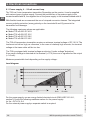
Monitoring of the measuring range:
If this function is activated, an error is signalled on the current loop (< 3.6 mA) if the
measured value is either below or over the limits of the measuring range.
Freely programmable monitoring functions when 2 sensors have been connected
(dual sensor)
The following options are not available in the difference mode!
Redundancy/hot backup:
In the case of a sensor error (sensor break, line resistance too high or measured value
outside the measuring range of the sensor) of one of the two sensors, the process value
will be the value from the working sensor only. Once the error is rectified, the process value
will again be based on the two sensors, or on sensor 1.
Ageing monitoring (sensor drift monitoring):
An error signal on the output is activated if the value of the temperature difference between
sensor 1 and sensor 2 is higher than a set value, which can be selected by the user. This
monitoring only generates a signal if two valid sensor values can be determined and the
temperature difference is higher than the selected limit value.
(Cannot be selected for the “Difference” sensor functionality, since the output signal
already indicates the difference value).
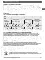
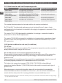
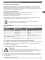
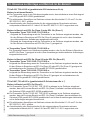
6.3.1 Configuration via the PC
To configure the transmitter, both configuration software and a HART
®
modem are needed.
WIKA offers 4 different HART
®
modem models for this.
VIATOR
®
HART
®
USB, order number: 11025166
VIATOR
®
HART
®
USB PowerXpress™, order number: 14133234
VIATOR
®
HART
®
RS-232, order number: 7957522
VIATOR
®
HART
®
Bluetooth
®
Ex, order number: 11364254
The HART
®
modem may also be used in conjunction with other configuration
software (see chapter 8 “WIKA T32 configuration software”).
6. Commissioning, operation
Seite wird geladen ...
Seite wird geladen ...
Seite wird geladen ...
Seite wird geladen ...
Seite wird geladen ...
Seite wird geladen ...
Seite wird geladen ...
Seite wird geladen ...
Seite wird geladen ...
Seite wird geladen ...
Seite wird geladen ...
Seite wird geladen ...
Seite wird geladen ...
Seite wird geladen ...
Seite wird geladen ...
Seite wird geladen ...
Seite wird geladen ...
Seite wird geladen ...
Seite wird geladen ...
Seite wird geladen ...
Seite wird geladen ...
Seite wird geladen ...
Seite wird geladen ...
Seite wird geladen ...
Seite wird geladen ...
Seite wird geladen ...
Seite wird geladen ...
Seite wird geladen ...
Seite wird geladen ...
Seite wird geladen ...
Seite wird geladen ...
Seite wird geladen ...
Seite wird geladen ...
Seite wird geladen ...
Seite wird geladen ...
Seite wird geladen ...
Seite wird geladen ...
Seite wird geladen ...
Seite wird geladen ...
Seite wird geladen ...
Seite wird geladen ...
Seite wird geladen ...
Seite wird geladen ...
Seite wird geladen ...
Seite wird geladen ...
Seite wird geladen ...
Seite wird geladen ...
Seite wird geladen ...
Seite wird geladen ...
Seite wird geladen ...
Seite wird geladen ...
Seite wird geladen ...
Seite wird geladen ...
Seite wird geladen ...
Seite wird geladen ...
Seite wird geladen ...
Seite wird geladen ...
Seite wird geladen ...
Seite wird geladen ...
Seite wird geladen ...
-
 1
1
-
 2
2
-
 3
3
-
 4
4
-
 5
5
-
 6
6
-
 7
7
-
 8
8
-
 9
9
-
 10
10
-
 11
11
-
 12
12
-
 13
13
-
 14
14
-
 15
15
-
 16
16
-
 17
17
-
 18
18
-
 19
19
-
 20
20
-
 21
21
-
 22
22
-
 23
23
-
 24
24
-
 25
25
-
 26
26
-
 27
27
-
 28
28
-
 29
29
-
 30
30
-
 31
31
-
 32
32
-
 33
33
-
 34
34
-
 35
35
-
 36
36
-
 37
37
-
 38
38
-
 39
39
-
 40
40
-
 41
41
-
 42
42
-
 43
43
-
 44
44
-
 45
45
-
 46
46
-
 47
47
-
 48
48
-
 49
49
-
 50
50
-
 51
51
-
 52
52
-
 53
53
-
 54
54
-
 55
55
-
 56
56
-
 57
57
-
 58
58
-
 59
59
-
 60
60
-
 61
61
-
 62
62
-
 63
63
-
 64
64
-
 65
65
-
 66
66
-
 67
67
-
 68
68
-
 69
69
-
 70
70
-
 71
71
-
 72
72
-
 73
73
-
 74
74
-
 75
75
-
 76
76
-
 77
77
-
 78
78
-
 79
79
-
 80
80


in anderen Sprachen
- English: WIKA T32.xS Operating instructions
Verwandte Artikel
-
WIKA TIF50 tag:model:TIF52 Bedienungsanleitung
-
WIKA T32.xS Bedienungsanleitung
-
-
-
-
-
-
-
WIKA UPT-20 tag:model:UPT-21 Bedienungsanleitung
-
Andere Dokumente
-
IFM TY9307 Installationsanleitung
-
IFM NM500A Bedienungsanleitung
-
-
IFM NG5016 Bedienungsanleitung
-
Sport-thieme Disc-Boccia Bedienungsanleitung
-
-
ICS T15 Digital temperature transmitter Benutzerhandbuch
-
 Kübler Codix 532 Benutzerhandbuch
-
 Kurtz Ersa DTM 100 Operating Instructions Manual
-
ABB TSHD Installation Instructions Manual

