
DE
EN
Operating instructions
Betriebsanleitung
Temperature controller, model CS4R
Universal controller for DIN-rail mounting
Model CS4R
Universalregler zur Montage auf Hutschiene
Typ CS4R

2 WIKA operating instructions model CS4R
14077287.01 09/2017 EN/DE
DE
EN
Operating instructions model CS4R
Page 3 - 42
Betriebsanleitung Typ CS4R
Seite 43 - 82
Further languages can be found at www.wika.com.
© 09/2017 WIKA Alexander Wiegand SE & Co. KG
All rights reserved. / Alle Rechte vorbehalten.
WIKA
®
is a registered trademark in various countries.
WIKA
®
ist eine geschützte Marke in verschiedenen Ländern.
Prior to starting any work, read the operating instructions!
Keep for later use!
Vor Beginn aller Arbeiten Betriebsanleitung lesen!
Zum späteren Gebrauch aufbewahren!

14077287.01 09/2017 EN/DE
WIKA operating instructions model CS4R 3
EN
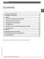
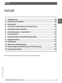
Contents
Contents
Declarations of conformity can be found online at www.wika.com.
1. General information 4
2. Design and function 5
3. Safety 8
4. Transport, packaging and storage 12
5. Commissioning, operation 13
6. “Transmitter” functionality 17
7. Configuration 18
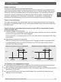
8. Descriptions of the operating characteristics 30
9. Control mode 33
10. Faults 36
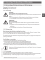
11. Maintenance and cleaning 40
12. Dismounting, return and disposal 41
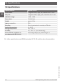
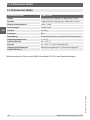
13. Specifications 42

14077287.01 09/2017 EN/DE
4 WIKA operating instructions model CS4R
EN
1. General information
■
The universal controller described in the operating instructions has been manufactured
using state-of-the-art technology. All components are subject to stringent quality and
environmental criteria during production. Our management systems are certified to
ISO 9001 and ISO 14001.
■
These operating instructions contain important information on handling the instrument.
Working safely requires that all safety instructions and work instructions are observed.
■
Observe the relevant local accident prevention regulations and general safety
regulations for the instrument’s range of use.
■
The operating instructions are part of the product and must be kept in the immediate
vicinity of the instrument and readily accessible to skilled personnel at any time. Pass
the operating instructions on to the next operator or owner of the instrument.
■
Skilled personnel must have carefully read and understood the operating instructions
prior to beginning any work.
■
The general terms and conditions contained in the sales documentation shall apply.
■
Subject to technical modifications.
■
Further information:
- Internet address: www.wika.de / www.wika.com
- Relevant data sheet: AC 85.05
- Application consultant:
Tel.: +49 9372 132-0
Fax: +49 9372 132-406
info@wika.de
1. General information

14077287.01 09/2017 EN/DE
WIKA operating instructions model CS4R 5
EN
2. Design and function
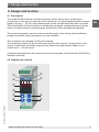
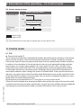
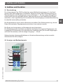
2.1 Description
The model CS4R universal controller features a multi-function input, meaning the
configuration of the sensor input can be set. Moreover, by using standard signals as input
signal, such as 4 ... 20 mA, other measurands can be recorded and thus also controlled.
Thus the flexibility of the controller is considerably increased, and warehousing is made
easier. An alarm output for monitoring the actual value is also available as standard.
The control parameters can be set across broad ranges. Auto-tuning, which facilitates
finding the optimal control parameters, can be activated.
The controllers are intended for DIN-rail mounting.
The monitoring output can be set either as relay (for slow control), as logic level for the
control of electronic solid state relays (for fast control and high current loads) or as a
continuous 4 ... 20 mA output.
A heater burnout alarm for the heater current monitoring and a serial interface RS-485 are
available optionally.
2.2 Display and controls
2. Design and function

14077287.01 09/2017 EN/DE
6 WIKA operating instructions model CS4R
EN
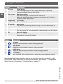
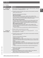
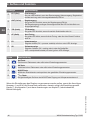
Display Description
EVT (red) Event display
The red LED lights up if the event output (alarm output, control loop
monitoring or heater burnout alarm) is ON.
OUT (green) Monitoring output
The green LED lights up if the monitoring output is ON.
(When the monitoring output is analogue current signal, the LED blinks in
proportion to the output power)
T/R (yellow) T/R display
The yellow LED lights up when serial interface is active.
AT (yellow) Auto-tuning
The yellow LED is blinking if the auto-tuning or the auto-reset function is
active.
PV Actual value display
The actual value (PV = process variable) is displayed with a red LED display.
SV Set point display
The set point (SV = setting value) or the manipulated variable (MV) is
displayed with a green LED display.
Button Description
Up button
Increases a numerical value or selects a setting parameter.
Down button
Reduces a numerical value or selects a setting parameter.
MODE button
Selects the setting mode and stores the selected setting parameter.
ON
/
OFF
button
Press the MODE button simultaneously to access the auxiliary parameter level 2.
When the settings for the controller must be set, first link connection terminals 1 and 2
for the power supply, then follow the setting in accordance with chapter 7 “Configuration”
(before moving on to chapter 5 “Commissioning, operation”)
2. Design and function

14077287.01 09/2017 EN/DE
WIKA operating instructions model CS4R 7
EN
2. Design and function
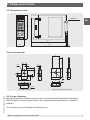
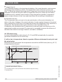
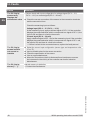
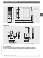
2.3 Dimensions in mm
Current transformer
2.4 Scope of delivery
Mounting materials: Sealing and screw-type mounting bracket (included as standard)
With the option “heater burnout alarm”, the required current transformer is included in
addition.
Cross-check scope of delivery with delivery note.
PV
SV
R
1
2
3
4
22,5
75
97
100
4
DIN rail
CTL-6S (for 20 A) CTL-12-S36-10L1 (for 50 A)
Ø 5,8
15
l
k
0,5
7,5
25
3
CTL-6-S
21
40
10,5
30
2-Ø3,5
K
L
10
2,8
30
l
k
100
40
40
Ø12
15
30
2-M3

14077287.01 09/2017 EN/DE
8 WIKA operating instructions model CS4R
EN
3. Safety
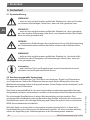
3.1 Explanation of symbols
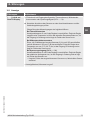
WARNING!
... indicates a potentially dangerous situation that can result in serious injury
or death, if not avoided.
CAUTION!
... indicates a potentially dangerous situation that can result in light injuries or
damage to property or the environment, if not avoided.
DANGER!
... identifies hazards caused by electrical power. Should the safety
instructions not be observed, there is a risk of serious or fatal injury.
WARNING!
... indicates a potentially dangerous situation that can result in burns, caused
by hot surfaces or liquids, if not avoided.
Information
... points out useful tips, recommendations and information for efficient and
trouble-free operation.
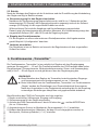
3.2 Intended use
The compact universal controller model CS4R is used to display, control and monitor
temperatures. In addition to the temperature, other measurands can also be recorded and
controlled via the multi-function input. This controller has been designed for mounting on a
DIN rail.
The instrument has been designed and built solely for the intended use described here,
and may only be used accordingly.
The technical specifications contained in these operating instructions must be observed.
Improper handling or operation of the instrument outside of its technical specifications
requires the instrument to be taken out of service immediately and inspected by an
authorised WIKA service engineer.
If the instrument is transported from a cold into a warm environment, the formation of
condensation may result in instrument malfunction. Before putting it back into operation,
wait for the instrument temperature and the room temperature to equalise.
The manufacturer shall not be liable for claims of any type based on operation contrary to
the intended use.
3. Safety

14077287.01 09/2017 EN/DE
WIKA operating instructions model CS4R 9
EN
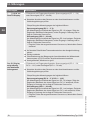
3.3 Improper use
WARNING!
Injuries through improper use
Improper use of the instrument can lead to hazardous situations and injuries.
▶
Refrain from unauthorised modifications to the instrument.
▶
Do not use the instrument within hazardous areas.
Any use beyond or different to the intended use is considered as improper use.
Do not use this instrument in safety or emergency stop devices.
3.4 Responsibility of the operator
The instrument is used in the industrial sector. The operator is therefore responsible for
legal obligations regarding safety at work.
WARNING!
Risk of damage to property
This is class A equipment for emissions and is intended for use in industrial
environments. In other environments, e.g. residential or commercial
installations, it can interfere with other equipment.
▶
Implement the appropriate measures.
The safety instructions within these operating instructions, as well as the safety, accident
prevention and environmental protection regulations for the application area must be
maintained.
The operator is obliged to maintain the product label in a legible condition.
To ensure safe working on the instrument, the operating company must ensure
■
that suitable first-aid equipment is available and aid is provided whenever required.
■
that the operating personnel are regularly instructed in all topics regarding work safety,
first aid and environmental protection and know the operating instructions and in
particular, the safety instructions contained therein.
■
that the instrument is suitable for the particular application in accordance with its
intended use.
3. Safety

14077287.01 09/2017 EN/DE
10 WIKA operating instructions model CS4R
EN
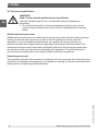
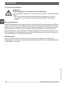
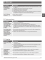
3.5 Personnel qualification
WARNING!
Risk of injury should qualification be insufficient
Improper handling can result in considerable injury and damage to
equipment.
▶
The activities described in these operating instructions may only be
carried out by skilled personnel who have the qualifications described
below.
Skilled electrical personnel
Skilled electrical personnel are understood to be personnel who, based on their technical
training, know-how and experience as well as their knowledge of country-specific
regulations, current standards and directives, are capable of carrying out work on
electrical systems and independently recognising and avoiding potential hazards. The
skilled electrical personnel have been specifically trained for the work environment they
are working in and know the relevant standards and regulations. The skilled electrical
personnel must comply with current legal accident prevention regulations.
Operating personnel
The personnel trained by the operator are understood to be personnel who, based on their
education, knowledge and experience, are capable of carrying out the work described and
independently recognising potential hazards.
3. Safety

14077287.01 09/2017 EN/DE
WIKA operating instructions model CS4R 11
EN
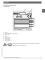
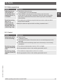
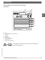
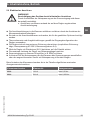
3.6 Labelling, safety marks
Product label
3. Safety
CS6S
2016-10
Code: CSxx-xx-xxxx
Spannungs- 100 ... 240 V ~
versogung: oder 24 V ~
Erz.-Nr.: xxxxxxxx
Fabrik-Nr.: xxxxxxxx
Hilfsenergie: xxxxxxxx
Eingang: Multifunktion
WIKA Alexander Wiegand SE & Co. KG
63911 Klingenberg
www.wika.com
Model
Date of manufacture (year-month)
Model code
Input
Power supply
Serial number
Article number
Voltage supply
Before mounting and commissioning the instrument, ensure you
read the operating instructions!

14077287.01 09/2017 EN/DE
12 WIKA operating instructions model CS4R
EN
4. Transport, packaging and storage
4. Transport, packaging and storage
4.1 Transport
Check the universal controller for any damage that may have been caused by transport.
Obvious damage must be reported immediately.
CAUTION!
Damage through improper transport
With improper transport, a high level of damage to property can occur.
▶
When unloading packed goods upon delivery as well as during internal
transport, proceed carefully and observe the symbols on the packaging.
▶
With internal transport, observe the instructions in chapter 4.2 “Packaging
and storage”.
If the instrument is transported from a cold into a warm environment, the formation of
condensation may result in instrument malfunction. Before putting it back into operation,
wait for the instrument temperature and the room temperature to equalise.
4.2 Packaging and storage
Do not remove packaging until just before mounting.
Keep the packaging as it will provide optimum protection during transport (e.g. change in
installation site, sending for repair).
Permissible conditions at the place of storage:
■
Storage temperature: -20 ... +50 °C (non-condensing, non-freezing)
■
Humidity: 35 ... 85 % relative humidity (non-condensing)
Avoid exposure to the following factors:
■
Direct sunlight or proximity to hot objects
■
Mechanical vibration, mechanical shock (putting it down hard)
■
Soot, vapour, dust and corrosive gases
■
Hazardous environments, flammable atmospheres
Store the instrument in its original packaging in a location that fulfils the conditions listed
above.

14077287.01 09/2017 EN/DE
WIKA operating instructions model CS4R 13
EN
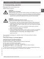
5. Commissioning, operation
5. Commissioning, operation
Personnel: Skilled electrical personnel
Tools: Phillips screwdriver
CAUTION!
Damage to the instrument
When working on open electrical circuits (printed circuit boards) there is a risk
of damaging sensitive electronic components through electrostatic discharge.
▶
The correct use of grounded working surfaces and personal armbands is
required when working with exposed circuitry (printed circuit boards).
DANGER!
Danger to life caused by electric current
Upon contact with live parts, there is a direct danger to life.
▶
The instrument may only be installed and mounted by skilled personnel.
▶
Operation using a defective power supply unit (e.g. short circuit from the
mains voltage to the output voltage) can result in life-threatening voltages
at the instrument!
▶
Before working on the connection terminals or cleaning the controller,
switch off the power supply to the controller.
▶
Never touch any live terminals.
▶
These controllers feature neither a built-in switch nor a fuse. It is therefore
necessary to install a fuse into the circuit external from the controller.
(Recommended fuse: Slow-acting, rated voltage AC 250 V,
rated current 2 A)
The controllers are designed for operation under the following ambient conditions
(IEC 61010-1):
Overvoltage category II, pollution degree 2
Avoid exposure to the following factors:
■
Direct sunlight or proximity to hot objects
■
Mechanical vibration, mechanical shock (putting it down hard)
■
Soot, vapour, dust and corrosive gases
■
Hazardous environments, flammable atmospheres
■
Ambient temperature: 0 ... 50 °C (32 ... 122 °F), without sudden changes
■
Humidity: 35 ... 85 % r.h. (non-condensing)
■
Not to be mounted close to electromagnetic switches or cables carrying high currents
■
Not for direct contact with water, oil, chemicals or their vapours

14077287.01 09/2017 EN/DE
14 WIKA operating instructions model CS4R
EN
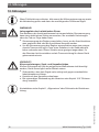
WARNING!
Damage to the instrument through improper use
The area of the display can easily be damaged.
▶
Avoid any contact with hard and sharp objects, or any excessive
pressures.
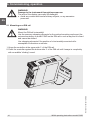
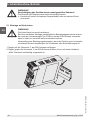
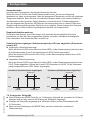
5.1 Mounting on a DIN rail
WARNING!
Mount the DIN rail horizontally!
Use the common clamping elements for the vertical mounting and mount the
universal controller of model CS4R on the DIN rail in such a way that it is fixed
and cannot be shifted.
Use clamping elements if the position of a horizontally mounted rail is
susceptible to vibrations or shocks.
1. Hinge the controller at the upper side of the DIN rail.
2. Press the controller against the bottom side of the DIN rail until it snaps in completely
with an audible “clicking” sound.
(1)
(2)
5. Commissioning, operation

14077287.01 09/2017 EN/DE
WIKA operating instructions model CS4R 15
EN
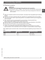
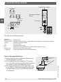
5.2 Electrical connection
WARNING!
Damage to the instrument through incorrect connection
Connecting the mains voltage to the sensor input will damage it permanently.
▶
Make the connections in accordance with the pin assignment attached to
the controller.
■
Feed the connection leads into the terminals, and secure them by tightening the terminal
screws.
■
Only the connection terminals which are needed for the selected options are provided.
■
Use thermocouples and compensating cables in accordance with the input configuration
of the controller.
■
The controllers must be protected with an external fuse (recommended fuse:
Slow-acting, rated voltage AC 250 V, rated current 2 A).
■
If the controller is to be operated with direct current (24 V), pay attention to the polarity.
■
Note the maximum power for the control and alarm outputs.
■
Protect the sensor inputs from external disturbances (e.g. EMC).
■
Under no circumstances should the mains voltage ever be connected to the sensor
input terminals or the connected sensor be brought into contact with the mains voltage.
When tightening the terminal screws, observe the maximum tightening torques listed in the
table:
Terminal screw Terminal No. Tightening torque
M2.6 1 to 4 max. 0.5 Nm
M2.0 5 to 9 max. 0.25 Nm
5. Commissioning, operation

14077287.01 09/2017 EN/DE
16 WIKA operating instructions model CS4R
EN
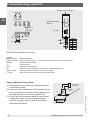
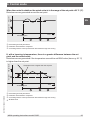
5. Commissioning, operation
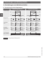
Option: Heater burnout alarm
(1) This alarm is not possible for measuring phase-
controlled currents.
(2) Use the current transformer (CT) supplied. Pass
one of the connection leads of the heating circuit
through the hole in the current transformer.
(3) Do not run the connection leads for the current
transformer close to any alternating current
sources or power lines, in order to avoid any
disruptive influences.
CT coupler
connector
Heating
circuit
CT
Heating
POWER SUPPLY
24V AC/DC
POWER SUPPLY
100 to 240V AC
MAIN OUTPUT
EVENT
OUTPUT
3A
250V AC
0.1A
24V DC
TC
RTD
DC V
DC mA
50Ω
(shunt resistor)
No.1
No.6
No.1
No.6
No.1
No.2
No.5
No.6
No.3
No.4
RS-485
COM
COM
NC
YA(-)
YB(+)
NC
Bottom of the controller
Optional interface
RS-485
CT input
POWER SUPPLY
24V AC/DC
POWER SUPPLY
100 to 240V AC
MAIN OUTPUT
EVENT
OUTPUT
3A
250V AC
0.1A
24V DC
TC
RTD
DC V
D
C mA
50Ω
(shunt resistor)
No.1
No.6
No.1
No.6
No.1
No.2
No.5
No.6
No.3
No.4
RS-485
COM
COM
NC
YA(-)
YB(+)
NC
RS-485 and optional connections
Legend:
MAIN OUTPUT Monitoring output
EVENT OUTPUT Output for alarm output 1, control loop monitoring and heater burnout alarm
RS-485 Serial interface RS-485
TC Thermocouple
RTD Resistance thermometer
DC Input DC current signal (DC mA) and DC voltage signal (DC V)
Shunt resistor 50 Ω measurement shunt for DC current signals
CT input Input current transformer for heater burnout alarm

14077287.01 09/2017 EN/DE
WIKA operating instructions model CS4R 17
EN
5. Commissioning, operation / 6. “Transmitter” functionality
5.3 Operation
After mounting the controller on the DIN rail and performing wiring, put the controller into
operation as follows:
■
Switch on the power supply for the controller.
Once the power supply has been switched on, the input configuration is displayed on the
actual value display (PV display) for about 3 seconds and, on the set point display, the
assigned end value can be seen.
During this time, all outputs and control displays are switched off.
Subsequently, the actual value display will show the current measured value, the set
point display will show the selected set point (SV1 or SV2) and it will start to control.
■
Input of the setting parameters
To enter one or more setting parameters, follow the procedure in accordance with
chapter 8 “Configuration”.
■
Switch on the load circuit
The control loop is now in operation and the control system will try to maintain the
selected set point.
6. “Transmitter” functionality
The “transmitter” functionality is only possible for controllers with the monitoring output
analogue current signal 4 … 20 mA. The transmitter function of CS4R converts each
input signal (thermocouples, resistance thermometers, current and voltage signals) into a
4 ... 20 mA signal and outputs it via the monitoring output.
WARNING!
■
When using the controller as a transmitter, there is a delay time of
approx. 1 s between the input and output signals.
■
When switching from the “transmitter” functionality to the “controller”
functionality, the settings from the transmitter mode are applied. After
switching to the controller mode, always check the settings required for
controlling and adjust them where necessary.
When operating the CS4R as a transmitter, proceed as follows:
1. Connect the controller (power supply, input and output).
2. Switch on the power supply for the controller.
3. Call the auxiliary parameter level 2 by pressing
- and MODE button
(for approx. 3 seconds).
4. Select the connected sensor in the menu item “Sensor selection (En)”.
5. Set the end value of the measuring range (measured value at which 20 mA are output) in
the menu item “Lettering end value (FLH)”.

14077287.01 09/2017 EN/DE
18 WIKA operating instructions model CS4R
EN
6. Set the start value of the measuring range (measured value at which 4 mA are output) in
the menu item “Start value scaling (FLL)”.
7. Select the “Transmitter (cn8F)” functionality in the menu item “Controller/transmitter
functionality (FUnc)”.
Notes:
For sensors with current or voltage signals the scaling is used to define both the display of
the controller as well as the measuring range of the output signal.
When switching to the transmitter mode, the settings listed in the table below are
applied by default:
Menu item Setting
Set point Start value scaling
Proportional band 100.0 %
Integral time 0 seconds
Derivative time 0 seconds
Manual reset setting 0.0
Alarm value 0
Control loop monitoring time 0 seconds
Control loop monitoring span 0
Heating/cooling control action Cooling (direct)
To activate alarm 1 in the transmitter mode, “Process high alarm” or “Process low alarm”
setting must be selected for the alarm type alarm 1.
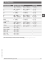
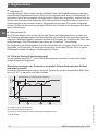
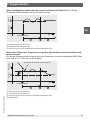
7. Configuration
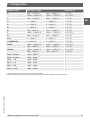
For the input configurations of thermocouples and resistance thermometers, after switching
the power on, for approx. 3 seconds, the type of the selected sensor and the temperature
units are shown on the actual value display, while at the same time the set point display
shows the scaled end value.
For the input configurations for current and voltage signals, the type of the sensor set and
the scaled end value are displayed.
During this time, all outputs and LED displays are switched off.
Subsequently, the actual value display will show the current measured value, the set point
display will show the selected set point and it will start to control.
6. “Transmitter” functionality / 7. Configuration

14077287.01 09/2017 EN/DE
WIKA operating instructions model CS4R 19
EN
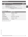
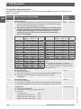
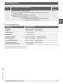
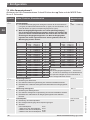
Sensor input Indication range Resolution
K -200 ... +1,370 °C
-199.9 ... +400.0 °C
-320 ... +2,500 °C
-199.9 ... +750.0 °C
1 °C (°F)
0.1 °C (°F)
J -200 ... +1,000 °C -320 ... +1,800 °C 1 °C (°F)
R 0 ... 1,760 °C 0 ... 3,200 °C 1 °C (°F)
S 0 ... 1,760 °C 0 ... 3,200 °C 1 °C (°F)
B 0 ... 1,820 °C 0 ... 3,300 °C 1 °C (°F)
E -200 ... +800 °C -320 ... +1,500 °C 1 °C (°F)
T -199.9 ... +400.0 °C -199.9 ... +750.0 °C 0.1 °C (°F)
N -200 ... +1,300 °C -320 ... +2,300 °C 1 °C (°F)
PL-II 0 ... 1,390 °C 0 ... 2,500 °C 1 °C (°F)
C (W/Re5-26) 0 ... 2,315 °C 0 ... 4,200 °C 1 °C (°F)
Pt100 -199.9 ... +850.0 °C
-200 ... +850 °C
-199.9 ... +999.9 °C
-300 ... +1,500 °C
0.1 °C (°F)
1 °C (°F)
JPt100 -199.9 ... +500.0 °C
-200 ... +500 °C
-199.9 ... +900.0 °C
-300 ... +900 °C
0.1 °C (°F)
1 °C (°F)
DC 4 ...20 mA -1999 ... 9999
1) 2)
1
DC 0 ... 20 mA -1999 ... 9999
1) 2)
1
DC 0 ... 1 V -1999 ... 9999
1)
1
DC 0 ... 5 V -1999 ... 9999
1)
1
DC 1 ... 5 V -1999 ... 9999
1)
1
DC 0 ... 10 V -1999 ... 9999
1)
1
1) The indication range and the decimal point are adjustable.
2) A 50 Ω measurement shunt (optionally available) must be connected between the input terminals.
7. Configuration

14077287.01 09/2017 EN/DE
20 WIKA operating instructions model CS4R
EN
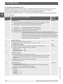
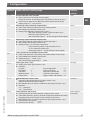
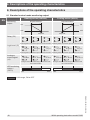
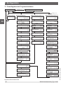
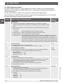
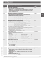
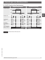
Actual value/Set point display Display of the output power
[Set point level] [Parameter level] [Auxiliary parameter level 2]
Set point
[]
AT auto-tuning
[a/re]
Monitoring output
Proportional band
[p]
Integral time
[]
Derivative time
[d]
ARW parameter
[a]
Monitoring output
Cycle time
[c]
Heater burnout alarm
Control loop monitoring
time
Control loop monitoring
span
[LP_H]
MODE (approx. 3 s)
+ MODE (approx. 3 s)
MODE
MODE
MODE
MODE
MODE
MODE
MODE
MODE
MODE
MODE
MODE
MODE
MODE
MODE
MODE
MODE
MODE
MODE
MODE
MODE
▲+ MODE
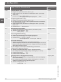
Sensor selection
End value scaling
[FLH]
Start value scaling
[FLL]
Decimal point
[dP]
Actual value filter
time constant
[FILF]
Monitoring output
max. output power
[oLH]
Monitoring output
min. output power
[oLL]
Hysteresis in the
OUT
/
OFF
control mode
[HY]
Alarm type alarm 1 (A1)
[AL1F]
MODE
[Auxiliary parameter level 1]
▼+ MODE (approx. 3 s)
MODE
MODE
MODE
MODE
Locking level
[Loct]
Sensor correction
[o]
Communication
protocol
Instrument address
Transmission rate
[cAP]
Parity
[cAPr]
Stop bit
[cA]
[cAL]
Manual reset setting
MODE
[rEF]
Alarm value alarm 1 (A1)
MODE
[A1]
[H]
[LP_F]
SVTC BIAS setting
Controller/transmitter
functionality
Output status with input
overshoot
MODE
MODE
MODE
[FUnc]
[8_b]
[EoUF]
[cAno]
MODE
MODE
MODE
MODE
MODE
MODE
Switch behaviour,
alarm 1 (A1)
[A1LA]
HOLD function,
alarm 1 (A1)
[AHLd]
Hysteresis alarm 1 (A1)
[A1HY]
Delay time, alarm
1 (A1)
[A1dY]
Heating/cooling
control action
[conF]
Auto-tuning BIAS
setting
[AF_b]
[En]
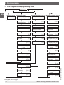
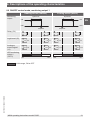
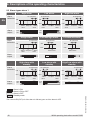
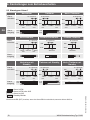
7.1 Flow diagram for the programming levels
For legend, see next page
7. Configuration
Seite wird geladen ...
Seite wird geladen ...
Seite wird geladen ...
Seite wird geladen ...
Seite wird geladen ...
Seite wird geladen ...
Seite wird geladen ...
Seite wird geladen ...
Seite wird geladen ...
Seite wird geladen ...
Seite wird geladen ...
Seite wird geladen ...
Seite wird geladen ...
Seite wird geladen ...
Seite wird geladen ...
Seite wird geladen ...
Seite wird geladen ...
Seite wird geladen ...
Seite wird geladen ...
Seite wird geladen ...
Seite wird geladen ...
Seite wird geladen ...
Seite wird geladen ...
Seite wird geladen ...
Seite wird geladen ...
Seite wird geladen ...
Seite wird geladen ...
Seite wird geladen ...
Seite wird geladen ...
Seite wird geladen ...
Seite wird geladen ...
Seite wird geladen ...
Seite wird geladen ...
Seite wird geladen ...
Seite wird geladen ...
Seite wird geladen ...
Seite wird geladen ...
Seite wird geladen ...
Seite wird geladen ...
Seite wird geladen ...
Seite wird geladen ...
Seite wird geladen ...
Seite wird geladen ...
Seite wird geladen ...
Seite wird geladen ...
Seite wird geladen ...
Seite wird geladen ...
Seite wird geladen ...
Seite wird geladen ...
Seite wird geladen ...
Seite wird geladen ...
Seite wird geladen ...
Seite wird geladen ...
Seite wird geladen ...
Seite wird geladen ...
Seite wird geladen ...
Seite wird geladen ...
Seite wird geladen ...
Seite wird geladen ...
Seite wird geladen ...
Seite wird geladen ...
Seite wird geladen ...
Seite wird geladen ...
Seite wird geladen ...
-
 1
1
-
 2
2
-
 3
3
-
 4
4
-
 5
5
-
 6
6
-
 7
7
-
 8
8
-
 9
9
-
 10
10
-
 11
11
-
 12
12
-
 13
13
-
 14
14
-
 15
15
-
 16
16
-
 17
17
-
 18
18
-
 19
19
-
 20
20
-
 21
21
-
 22
22
-
 23
23
-
 24
24
-
 25
25
-
 26
26
-
 27
27
-
 28
28
-
 29
29
-
 30
30
-
 31
31
-
 32
32
-
 33
33
-
 34
34
-
 35
35
-
 36
36
-
 37
37
-
 38
38
-
 39
39
-
 40
40
-
 41
41
-
 42
42
-
 43
43
-
 44
44
-
 45
45
-
 46
46
-
 47
47
-
 48
48
-
 49
49
-
 50
50
-
 51
51
-
 52
52
-
 53
53
-
 54
54
-
 55
55
-
 56
56
-
 57
57
-
 58
58
-
 59
59
-
 60
60
-
 61
61
-
 62
62
-
 63
63
-
 64
64
-
 65
65
-
 66
66
-
 67
67
-
 68
68
-
 69
69
-
 70
70
-
 71
71
-
 72
72
-
 73
73
-
 74
74
-
 75
75
-
 76
76
-
 77
77
-
 78
78
-
 79
79
-
 80
80
-
 81
81
-
 82
82
-
 83
83
-
 84
84


in anderen Sprachen
- English: WIKA CS4R Operating instructions
Verwandte Artikel
-
WIKA CS6H tag:model:CS6L tag:model:CS6S Bedienungsanleitung
-
-
-
-
WIKA T32.xS Bedienungsanleitung
-
-
-
-
WIKA UPT-20 tag:model:UPT-21 Bedienungsanleitung
-
