Seite wird geladen ...

Installation Instructions | Installationsanleitung | Notice d’installation
Istruzioni per l’installazione | Instrucciones de instalación
Minebea Intec
YDO01M-232 (A11)
YDO01M-232CLK (A31)
YDO01M-232CO (A1)
YDO01M-485 (A2 | A3)
YDA01M-20MA (A9)
YDO01M-IO (A5)
YDO01M-EN (B9)
Data Output Port for Midrics® COM1 and UniCOM Interfaces
Datenausgang für Midrics®-Schnittstellen COM1 und UniCOM
Port de sortie pour interfaces Midrics® COM1 et UniCOM
Porta in uscita per interfacce Midrics® COM1 e UniCOM
Puerto de salida para interfaces COM1 y UniCOM de Midrics®
98647-004-16
98647-004-16

2YDO01M
Contents
English – page 3
In cases involving questions of interpretation, the German-language version shall prevail.
Deutsch – Seite 20
Im Auslegungsfall ist die deutsche Sprache maßgeblich.
Français – page 37
En cas de questions concernant l’interprétation, la version en langue allemande fera autorité.
Italiano – pagina 54
In caso di interpretazione dubbia, fa testo la versione in lingua tedesca.
Español – página 71
En caso de interpretación, la versión en lengua alemana será determinante.

3
YDO01M
Contents
Intended Use
The YD.01M-... data output port is
designed for installation in Midrics®
model MIS... and MW... display and
control units and complete scales as an
optional standard COM1 interface or
UniCOM universal data interface.
For COM1:
– YDO01M-232 (Option A11):
Bidirectional RS-232 data interface.
You can connect the following to the
YDO01M-232 port: Printer (YDP02IS,
YDP03, YDP04IS, YDP12IS, universal
printer) or computer (SBI, XBPI or SMA
operation).
– Alibi memory
– YBT01 external Bluetooth adapter
– YRD02Z second display
– USB adapter cable, for connecting
a computer over USB (part no.
YCC01IS).
– YDO01M-232CLK “Clock" (Option A31):
As standard RS-232, plus date/time
For UniCOM:
– YDO01M-232CO (Option A1):
as for RS-232, plus digital I/O (TTL/5V)
– YDO01M-485 (Options A2 and A3):
Bidirectional data interface, electri-
cally isolated, for use with the RS-422
(Option A2) or RS-485 (Option A3) pro-
tocol.
The YDO01M-485 lets you network up
to 32 Midrics scales/display and control
units in an XBPI-bus.
– YDA01M-20MA (Option A9):
Analog output port for use as a current
interface (0/4 to 20 mA, 0 - 24 mA) or
voltage interface (0 to 24 volts).
The YDA01-20MA module enables con-
nection of a PLC system or a remote
analog display unit.
– YDO01M-IO (Option A5):
Digital input/output module; for con-
necting Midrics equipment to external
controllers.
– YDO01M-EN (Option B9):
Ethernet interface (e.g. for connecting
to a PLC or PC).
Symbols
The following symbols are used in
these instructions:
§ indicates required steps
$ indicates steps required only under
certain conditions
> describes what happens after you
have performed a particular step
! indicates a hazard
Contents
3 Intended Use
4 Installation in the Display and
Control Unit
4 Installing the COM1 PCB
5 Installing the UniCOM PCB
7 Installing the Interface Cable
8 Configuring the Interface Module:
YDO01M-485, YDA01M-20MA
10 YDO01M-IO: Specifications
10 YDO01M-EN
11 Pin Assignment Charts
11 COM1
11 UniCOM
12 Configuring COM1 and UniCOM
16 Synchronization
17 Data Interfaces
17 Data Input Format (Commands)
18 Data Output Format
19 GMP-compliant Printouts

4YDO01M
Installation in the Display and Control Unit Installation in the Display and Control Unit
Installation in the Display and Control Unit
Installation
Installation of the interface module in the Midrics display and control unit (and addi-
tionally the installation of the cable gland and connection of the connecting cable to
the terminal screw strip) is only required if the Midrics display and control unit was not
equipped at the factory with this data output in accordance with the customer's order.
Notes:
§ The interface module should be installed by a certified technician who has received
specialized training from Minebea Intec .
§ IP65 protection:
Make sure to use the connecting cable with screw-lock hardware designed for the inter-
face module in question (see “Accessories").
! Make sure to disconnect the equipment from power before beginning installation.
! Any installation work that does not conform to the instructions in this manual will result
in forfeiture of all claims under the manufacturer's warranty.
! Installation work that affects the IP65 protection rating must be performed with extreme
care.
The cable gland (IP65 protection) for connection of the interface to the display and con-
trol unit is covered by a protective cap. Please use extreme caution when performing any
work on the equipment that affects this cable gland.
§ To open the display and control unit, remove the screws from the front panel.
Installing the COM1 PCB:
§ Remove fastening screw.

5
YDO01M
Installation in the Display and Control Unit
§ Attach spacing bolts.
§ Plug in PCB mounting.
§ Plug the interface module (YDO01M-232 or YDO01M-232CLK) onto the digital PCB
in the Midrics display and control unit. To do this, attach the female terminal strips on
the interface module to the corresponding male terminal strips on the digital PCB.
§ Fasten the interface module with the screw.
The interface modules are equipped with their own terminal screw strips.
Connect the cable to this terminal strip.
Installing the UniCOM PCB:
§ Remove the 2 fastening screws.

6YDO01M
Installation in the Display and Control Unit Installation in the Display and Control Unit
§ Attach the 2 spacing bolts.
§ Plug in PCB mounting.
§ Plug the interface module (YDO01M-232CO, YDO01M-485, YDA01M-20MA or
YDO01M-IO) onto the digital PCB in the Midrics display and control unit. To do this,
attach the female terminal strips on the interface module to the corresponding male
terminal strips on the digital PCB.
§ Fasten the interface module with the 2 screws.
The interface modules are equipped with their own terminal screw strips.
Connect the cable to this terminal strip.

7
YDO01M
Installation in the Display and Control Unit
Installing the Interface Cable
§ Pin assignments: please see “Pin Assignment Charts" in this manual.
§ Use the cable gland to connect the peripheral device to the indicator.
§ Prepare the cable as follows:
– Expose approximately 10 cm (4 in) of the cable end for installation
– Remove all but approximately 1 cm (1/2 inch) of the shielding and fold it back over the
casing
– Strip the casing from approximately 1 mm (1/2 inch) of the wires and attach ferrules to
the wire ends.
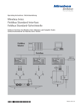
§ Attach the cable gland:
!Please use extreme caution when performing any work on the equipment that affects this
cable gland. Use a torque wrench and tighten the cable gland to 5 Nm.
– Remove the protective cap from the bore hole on the display and control unit.
– Guide the enclosed cable gland through the bore hole and secure it inside the housing
with the nut (1).
– Slide the cable gland over the cable until the clamps (3) are in contact with the shield
(2). Tighten the nut (4) until the sealing clamp (5) forms a slight ridge between nut and
cable.
– Make sure the shield is in contact with the clamps.
§ Connect the cable:
– Connect the wires securely in accordance with the terminal assignments.
– Please see “Pin Assignment Charts" in this manual for details.
§ Close the display and control unit. Make sure that the rubber seal between the front
panel and the housing is correctly positioned.
§ After you close the housing again, use a pressure gauge to check the integrity of the IP65
protection. For details, contact the Minebea Intec Service Center.
Setting the Operating Parameters in the COM1 and UniCOM Interfaces
After installing and configuring the interface module in the display and control unit,
select the parameters in the operating menu that correspond to your requirements.
For details, see “Configuring COM1 and UniCOM." For more information, refer to the
installation and operating instructions for the Midrics scale.
4
15
2
3
8765
4

8YDO01M
Configuring the Interface Module
Configuring the Interface Module
Configuring the Interface Module:
YDO01M-485, YDA01M-20MA
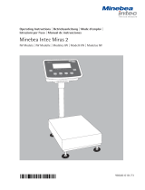
YDO01M-485 (Options A2 and A3)
Characteristics
The YDO01M-485 module (serial RS-485/RS-422 interface, electrically isolated1) can be
operated with your choice of RS-485 or RS-422 protocol.
The module is configured by eight switches.
In addition to defining whether RS-485 or RS-422 is used, certain terminating resistors
(120 O) and/or bias resistors may have to be activated or deactivated, depending on
whether a network or point-to-point connection is used.
The positions of the switches are indicated in the drawing on the left. Close switches 1
through 4 for RS-422 operation.
The following list shows the functions of switches in the closed (“ON") position:
Function (on = closed) Switch
Terminating resistor, transmitting side 120O 1 - 1
Bias resistor, transmitting side (TxD+, pull-up) 680O 1 - 2
Bias resistor, transmitting side (TxD–, pull-down) 680O 1 - 3
ON: RS-422 operation | open: RS-485 mode 1 - 4
Terminating resistor, receiving side 120O 2 - 1
Bias resistor, receiving side (RxD+, pull-up) 680O 2 - 2
Bias resistor, receiving side (RxD–, pull-down) 680O 2 - 3
No function 2 - 4
Note on setting the switches:
Switches must be set pairwise as follows:
– Switches 1–2 and 1–3: both ON or both OFF
– Switches 2–2 and 2–3: both ON or both OFF
Operation as an RS-485 Interface (Option A3):
§ Switches 1 - 4 must be open to operate the module in RS-485 mode (factory setting).
§ If necessary, deactivate the bias resistors for the RS-485 mode. To do this, open the
switch (factory setting).
The bias resistors must occur no more than once per data transmission path (whether
over a network or in a point-to-point connection); otherwise, transmission errors may
occur. Please refer to the specifications or wiring diagram for the remote station or
network node in question for detailed information. Always activate or deactivate bias
resistors in pairs.
§ The terminating resistor (transmitting side, switch 1 – 1) must be activated if the device
is at either end of an RS-1 bus system, or when connected point-to-point with another
device. The remote station must also have a 120-O terminating resistor. If necessary,
activate the terminating resistor (120 O) for RS-485 operation:
close switches 1 - 1 and 2 - 1 (“ON")
Operation as an RS-422 Interface (Option A2):
§ Close switches 1 - 4 for RS-422 operation (“ON")
§ If necessary, deactivate the bias resistors for RS-422-operation. To do this, open the
switches.
§ Activate the terminating resistor on the receiving side (switch 2 – 1), if no external ter-
minating resistor is available. Always deactivate terminating resistors on the transmitting
side (switch 1 – 1).
1) The shielding in the connecting cable is connected at one end to the housing of the indicator.
The indicator is connected to the protective grounding conductor.

9
YDO01M
Configuring the Interface Module
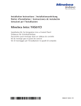
YDA01M-20MA (Option A9)
Features
Interface module YDA01M-20MA is an analog output port. It can be operated as a current
interface (0/4 – 20mA, 0 – 24 mA) or as a voltage interface (0 to 10 V). The voltage supply is
internally galvanically isolated.
It is delivered with the PCB in 4-20mA operating state.
The interface module can be configured for any one of the following four operating states:
– Voltage interface, 0 to 10 V
– Current interface, 0 to 20 mA
– Current interface, 4 to 20 mA
– Current interface, 0 to 24 mA
Configuring the module for the intended use involves opening and closing certain switches.
The positions of the switches are indicated in the drawing on the left.
The operating state is defined by the configuration of switches 1 and 2 (switches 3 and 4
have no function):
– Max. load: 390 ohms
Notes
– The screen of the current interface connecting cable is connected to the indicator housing at
one end.
– The indicator is connected to the protective grounding conductor.
– If the indicator is powered using an internal or external rechargeable battery pack, it is not
possible to operate the current interface.
§ Interface module YDA01M-20MA is attached directly onto the digital PCB of the Midrics
indicators (MIS..., MW...). For more information, please refer to the section entitled
“Installing in the Indicator”.
Example: Connect platform with 20 kg max. load Multimeter to terminal 1 and 2 on the
terminal block.
§ Configure switch SW 1 before switching on the device
§ Configure the SW switch on the YDA01M-20MA PCB.
SW1 and SW2 ON = 0mA at 0 g and 24mA at 20 kg
§ Switch on the Midrics, the scale is adjusted.
§ Select in the Unicom/ Analog/ menu.
§ When no load is on the weighing pan, 4 mA should be displayed on the Multimeter and
20mA under max. load. If these values should deviate, the value can be preconfigured in
the menu under Setup / Unicom / Analog/ 8.16.1 and 8.16.2.
§ Select 8.16.1 (lower value). Midrics now generates a current requirement of approx. 3.99
mA on the Multimeter; enter this value on the keypad.
§ Select 8.16.2 (upper value). Midrics now generates a current requirement of approx.
20.00 mA on the Multimeter; enter this value on the keypad.
§ Exit menu and verify with weights.
SW1-1 SW1-2 Mode
Open Open 4-20mA
Closed Open 0-10V
Open Closed 0-20mA
Closed Closed 0-24mA
Terminal Function
1I_out (+)
2I_in (-)
3V_out (+)
4V_in (-)
5GND galvanic
isolation
6GND galvanic
isolation

10 YDO01M
Configuring the Interface Module
Configuring the Interface Module
Example: Basic Circuit Diagram
YDO01M-IO, Option A5:
Specifications
Digital inputs
– Quantity: 5
– Low level: –3 V to +5 V
– High level: +11 V to +30 V
– Maximum current
consumption: 2.6 mA at 15 V
– Inputs are activated by applying
the corresponding voltage.
Digital outputs
– Quantity: 5
– Maximum current flow per channel:
100 mA
– Voltage range: 0–30 VDC
– Each output is formed
by an opto-electronic coupler.
YDO01M-EN (Option B9)
Equipment Supplied
– YDO01M-EN interface module
– Operating instructions (this document)
– Interface description (fieldbus for
TCP Modbus)
Assembly
Connect interface module YDO01M-
EN (Ethernet interface) directly to the
digital board of the scales without con-
figuration. For more information, please
refer to chapter entitled “Installing Data
Output Ports in the Indicator”.
Insert the YCC02RJ45M7 plug on the
Minebea Intec Ethernet cable (option
M38) into the port of the interface
module.
Note:
! Only use cables and plugs that conform
to the Ethernet specification (CAT5 or
better):
Ethernet cable with Minebea Intec
order no. YCC02RJ45M7 (Option M38)
cable gland
Use the interface module only with the
following devices:
– Indicator MIS1, MIS2 (IP65)
– Complete scales MW1, MW2 (IP65)
OUTx_high
30V
0.2A
Inputx_high
LV1
LV1
OUTx_low
1
23
4
1
23
4
LV2
LV2
Inputx_low
OUTx_high
30V
0.2A
Inputx_high
LV1
LV1
OUTx_low
1
23
4
1
23
4
LV2
LV2
Inputx_low

11
YDO01M
Configuring the Interface Module
Pin Assignment Charts
COM1
– RS-232 interface: YDO01M-232
(Option A11), YDO01M-232CLK (A31):
Pin assignments in the 8-contact termi-
nal screw strip on the interface module:
Pin 1: +12 V: Supply voltage for
Minebea Intec printers
Pin 2: Reset_Out
(peripheral device restart)
Pin 3: +5 V Out
Pin 4: Ground (GND)
Pin 5: Clear to send (CTS)
Pin 6: Data terminal ready (DTR)
Pin 7: Data input (R+D)
Pin 8: Data output (T+D)
UniCOM
– Pin assignments in the two 10-contact
terminal screw strips on the interface
module:
RS-232 interface: YDO01M-232CO
(Option A1):
Pin 1: Clear to send (CTS)
Pin 2: Data terminal ready (DTR)
Pin 3: Data input (R+D)
Pin 4: Data output (T+D)
Pin 5: Ground (GND)
Pin 6: Universal IN
Pin 7: Control output: “lighter"
Pin 8: Control output: “equal"
Pin 9: Control output: “heavier"
Pin 10: Control output: “set"
Pin 11: +12 V: Supply voltage for
Minebea Intec printers
Pin 12: Reset_Out
(peripheral device restart)
Pin 13: Ground (GND)
Pin 14: Ground (GND)
Pin 15: +5 V output
Pin 16: +5 V switched
(e.g., for bar code scanner)
Pin 17: Ground (GND)
Pin 18: Ground (GND)
Pin 19: Not connected
Pin 20: Ext. supply voltage output
+15V to 25V
Digital I/O interface:
YDO01M-IO (Option A5):
Pin 1: External output port 5: low
Pin 2: External output port 5: high
Pin 3: External output port 4: low
Pin 4: External output port 4: high
Pin 5: External output port 3: low
Pin 6: External output port 3: high
Pin 7: External output port 2: low
Pin 8: External output port 2: high
Pin 9: External output port 1: low
Pin 10: External output port 1: high
Pin 11: Input port 5: low
Pin 12: Input port 5: high
Pin 13: Input port 4: low
Pin 14: Input port 4: high
Pin 15: Input port 3: low
Pin 16: Input port 3: high
Pin 17: Input port 2: low
Pin 18: Input port 2: high
Pin 19: Input port 1: low
Pin 20: Input port 1: high
– Pin assignments in the two terminal
screw strips on the interface module:
1
234566
YDO01M-485: RS-485 mode
(Option A2):
Pin 1: Data + (T+D-R+D+)
Pin 2: Data - (T+D-R+D-)
Pin 3: Not connected
Pin 4: Not connected
Pin 5: Signal ground, electrically
isolated (GND_GALV)
Pin 6: Signal ground, electrically
isolated (GND_GALV)
Pin 11: Ext. supply voltage input
+15V to 25V *
Pin 12: Ext. supply voltage input
+15V to 25V *
Pin 13: Ground (GND) *
Pin 14: Ground (GND) *
1
234566
1
234566
YDO01M-485: RS-422 mode
(Option A3):
Pin 1: Data output + (T+D+)
Pin 2: Data output - (T+D-)
Pin 3: Data input + (R+D+)
Pin 4: Data input - (R+D-)
Pin 5: Signal ground, electrically
isolated (GND_GALV)
Pin 6: Signal ground, electrically
isolated (GND_GALV)
Pin 11: Ext. supply voltage input
+15V to 25V *
Pin 12: Ext. supply voltage input
+15V to 25V *
Pin 13: Ground (GND) *
Pin 14: Ground (GND) *
* = Not electrically isolated
YDA01M-20MA
(current/voltage interface):
6-pin terminal screw strip on the inter-
face module
1
234566
Pin 1: I_out (+)
for current interface
(0/4 to 20/24 mA)
Pin 2: I_in (–)
for current interface
(0/4 to 20/24 mA)
Pin 3: V_out (+)
for voltage interface,
0V to + 10V
Pin 4: V_in (–)
for voltage interface,
0V to + 10V
Pin 5: GND, electrically isolated
(electrically isolated ground)
Pin 6: GND, electrically isolated
(electrically isolated ground)
tPin assignment of the
Ethernet interface (RJ45)
YDO01M-EN (Option B9):
Pin 1: TxD+
Pin 2: TxD-
Pin 3: RxD+
Pin 4: Not in use
Pin 5: Not in use
Pin 6: RxD-
Pin 7: Not in use
Pin 8: Not in use
Chassis: GND
1
234566
1
234566

12 YDO01M
Configuring COM1 and UniCOM
Configuring COM1 and UniCOM
Configuring COM1 and UniCOM
Operating menu overview for the COM1 and UniCOM interfaces
(see also “Operating Menu Overview" in the chapter entitled “Configuration" in the Midrics operating instructions).
Appl
Fn-Key
Setup WP-1
COM1 OFF *
DATPROT SBI *
(data record) XBPI-232
SMA
Printer YDP01IS Line *
Label
Label, man. form feed
YDP02
YDP03
YDP02IS Line *
Label
UNI-PRI (universal printer)
YDP04IS Line *
Label
Label, man. form feed
MEMORY YAM01IS (Alibi memory)
UniCOM OFF *
DATPROT SBI *
(data record) XBPI-232
XBPI-485
SMA
ETHERNET Source IP: 192.168.0.1 *
Source name
Listen port: 49155 *
Subnet mask: 255.255.255.0 *
Gateway IP: 0.0.0.0 *
DNS IP: 0.0.0.0 *
Target IP: 0.0.0.0 *
Target port: 49155 *
Protocol TCP *
UDP
Mode SBI (server)-SRV* 6.1. Data output manual/automatic
6.1.1 Manual without stability
6.1.2 * Manual after stability
6.1.7 Print log for PC
7.2. Output: line format
7.2.1 For raw data: 16 characters
7.2.2 * For other apps: 22 characters
SBI-C/S 6.1. Data output manual/automatic
(client) 6.1.1 Manual without stability
6.1.2 * Manual after stability
6.1.4 Automatic without stability
6.1.5 Automatic with stability
6.1.7 Print log for PC
6.3. Time-dependent autom. output
6.3.1 * 1 display cycle
6.3.2 2 display cycles
6.3.4 10 display cycles
6.3.7 100 display cycles
7.2. Output: line format
7.2.1 For raw data: 16 characters
7.2.2 * For other apps: 22 characters
xBPI
SMA
Modbus/TCP

13
YDO01M
Configuring COM1 and UniCOM
Setup UniCOM Printer YDP01IS Line *
Label
Label, man. form feed
YDP02
YDP03
YDP02IS Line *
Label
UNI-PRI (universal printer)
YDP04IS Line *
Label
Label, man. form feed
MEMORY YAM01IS (Alibi memory)
ANALOG (analog interface)
CTRL IO: CTR INP: 8. 4. x TTL; for YDO01M-232CO, Option A1
Control Control inputs 8. 17. x Electrically isolated; for
inputs/ to YDO01M-IO, Option A5
outputs 8 . 21. x
CTR OUT: 8. 24. x Electrically isolated; for
Control to YDO01M-IO, Option A5
outputs 8. 28. x
* = Factory setting

14 YDO01M
Configuring the Interface
Configuring the Interface
Ethernet interface
In the “UNICOM” menu, select
“ETHERNET” to enter numerical
values under Source IP, ListenPort, etc.
Under Source name, both letters and
numbers can be used. A maximum of
15 characters can be entered. Enter
either a source name or a source IP
address (not both).
Port numbers
Validity range: 0 – 65535
Since many of the ports up to 49150
have already been allocated, we recom-
mend using port numbers above 49150.
This does not apply to Modbus/TCP,
because the following port number
applies here: 502 (see the fieldbus bro-
chure for details)
Configuring the Interface
You can configure the UniCOM univer-
sal data interface for the required oper-
ating state (connection of a peripheral
device).
The diagram on the preceding page
shows the relevant section of the
operating menu.
For additional information, see the
chapter entitled “Settings" in the Mid-
rics operating instructions.
RS-485/RS-422 Interface
If the PCB is configured for use in the
RS-422 operating mode, you can select
the SBI, XBPI-232, or SMA menu item.
YDA01M-20MA Analog Interface
You can configure the following
parameters in the operating menu:
– Output value (menu line 8.12):
8.12.1: Net value
(factory setting)
8.12.2: Gross value
– Error display (menu line 8.13):
8.13.1: High level (20 mA)
(factory setting)
8.13.2: Low level (0/4 mA):
5V on this interface during
operation.
– Output mode (menu line 8.14):
8.14.1: Zero to maximum capacity
(factory setting)
8.14.2: Minimum/maximum values
– Output of minimum/maximum values
(menu line 8.15):
8.15.1: Min. (0/4 mA) input in kg
8.15.2: Max. (20 mA) input in kg
By selecting min./max. values you can
specify the weighing range for output
on the 0/4 to 20mA (0 to 10 V) inter-
face. This selection applies as well to an
SBI scale, but only for the net value.
Input of min. and max. values is always
in kilograms. You can enter negative
values if desired. You can also enter a
min. value that is higher than the max.
value, to effect falling current output.
Examples:
Rising current curve
Min. value, net: -1 kg
Max. value, net: 4 kg
Falling current curve for XBPI scales
Min. value: 5 kg
Max. value: 1 kg
Falling current curve for SBI scales
Min. value: 5 kg
Max. value: 1 kg

15
YDO01M
Configuring the Interface
Ethernet interface: Initialization
Display: Initialization completed
Once initialization of the Ethernet
module has been completed successfully,
the “ ” symbol is displayed.
Network module
initialized
If initialization was not successful,
no symbol is displayed. The symbol
provides no information about the
connection status in relation to the
network.
TCP connections:
In the SBI-C/S operating mode, Midrics
always terminates the connection
independently, after 1 second.
In the other operating modes
(SBI-SRV, SMA, XBPI, ModBus/TCP) the
connection is maintained until it is dis-
connected by the PC (client). It is only
possible to establish one connection at
a time.
Ethernet interface: Features
Source IP: IP address of the Midrics indicator
If the address 0.0.0.0 is selected, you need to enter a name under
“Source name.” In this case, the IP address should be dynamically allocated
by a DHCP server located within the network.
Source name: This parameter is alternative to the “Source IP” input. A name that is up
to 15 characters in length and serves to identify the Midrics can be entered.
In this case, the address 0.0.0.0 must be selected as the source IP. The name
is announced to the domain name service (DNS) if
– an IP address has been entered under DNS IP
or
– an IP address has been allocated over DHCP.
Device port: Number of the port on which the Midrics listens for server operation.
Subnet mask: IP address mask for the activation of IP addresses in a subnet. If the mask
is to be allocated using a DHCP server, 0.0.0.0 must be entered.
Gateway IP: IP address of a gateway
Address of desired server located in another network using target IP. If the IP
address is to be allocated dynamically using a DHCP server, 0.0.0.0 must be
entered.
Target IP: Address of the server that is to receive the Midrics data.
Important for operation of the Midrics as a client if the SBI mode has been
selected in combination with automatic data output. When using UDP,
an IP address must also be entered here.
Target port: Port number on which a server with the target IP listens in order to receive
data from the Midrics.
Protocol: Select the transport protocol to be used to transmit data over Ethernet.
Please select either:
– TCP, connection-oriented with high data security
or
– UDP, connectionless (does not effect Modbus/TCP)
Mode: Select the data format that contains the user data embedded in TCP or UDP
(e.g. SMA is tunnelled over Ethernet using TCP or UDP).
With the SBI-SRV, XBPI and SMA protocols, the Midrics is always to be seen
as a server. Under SBI-C/S, the Midrics is simultaneously a server and a cli-
ent. Client mode is activated when the p [Print] button is pressed or the
data output parameter has been set to “automatic”. For the OPC mode, set
the menu code for “SBI server.” In all other instances, the Midrics is a server.
Under ModBus/TCP, the Midrics is always active as a server (also see the field
bus brochure).
Power-on
response: If the interface module is active, the display of the weight value may be
delayed by up to 20 seconds.

16 YDO01M
Data Interfaces Configuring the Interface
Synchronization
Data communication between the
display and control unit and a com-
puter takes the form of messages (“tel-
egrams") made up of ASCII code. For
error-free data communication, the set-
tings for baud rate, parity, handshake
mode and character format must be the
same at both ends.
You can configure the interface settings
in the Setup menu so that they match
those of the computer. You can also
define parameters in the indicator to
make data output dependent on various
conditions. The conditions that can be
configured are listed in the descriptions
of the application programs (see oper-
ating instructions for the Midrics scale).
If you do not connect a periph-
eral device to the display and control
unit's interface port, this will not gener-
ate an error message.
Handshake
The weighing instrument interface
(Minebea Intec Balance Interface = SBI)
has transmit and receive buffers. You
can define the handshake parameter
in the display and control unit's Setup
menu:
– Hardware handshake (CTS/DTR)
– Software handshake (XON, XOFF)
Hardware Handshake
Hardware handshake with a 4-wire
interface: 1 more character can be
transmitted after CTS (clear-to-send).
Software Handshake
The software handshake is controlled
via XON and XOFF. When a device is
switched on, XON must be transmitted
to enable a connected device to com-
municate.
The data transmission sequence is as
follows:
Scale ––– byte –––> Computer
(trans- ––– byte –––> (receiving
mitting device)
device)
––– byte –––>
––– byte –––>
<–– XOFF –––
––– byte –––>
––– byte –––>
...
(Pause)
...
<–– XON –––
––– byte –––>
––– byte –––>
––– byte –––>
––– byte –––>
Transmitting Device
Once XOFF has been received,
it prevents further transmission of
characters. When XON is received, it re-
enables the transmitting device to send
data.
Receiving Device
To prevent too many control commands
from being received at one time, XON
is not transmitted until the buffer is
almost empty.

17
YDO01M
Data Interfaces
Data Interfaces
Configuring the Data
Interface as a COM Port
(datprot)
Configure the interface as a COM port
in the Setup menu under COM1 or
UniCOM, under the “Data Protocol"
(datprot) menu item.
SBI Communication
This is a simple ASCII interface.
Data output is configured under menu
lines 6.1 and 6.3:
– Manual output of displayed value with
or without stability (menu items 6.1.1
and 6.1.2)
– Automatic output of displayed value
with or without stability (menu items
6.1.4 and 6.1.5) at intervals defined by
display updates. The number of display
updates comprising an output interval
is configured under menu item 6.3.
– Output of a configurable printout.
Output is linked to the Printout
(prtprot) settings.
If you do not activate and configure a
user-definable data record, the print-
out simply contains the current value
displayed on the indicator (weight with
unit, calculated value, alphanumeric
display).
SMA Communication
Standardized communications protocol
of the Scale Manufacturers Association
Data Input Format
(Commands)
You can connect a computer to your
display and control unit to send com-
mands controlling weighing instrument
functions and applications via the inter-
face port.
All commands use the same format
(data input format) starting with the
ESC character (ASCII 27) and ending
with a carriage return (CR; ASCII 13)
and a line feed (LF; ASCII 10). The total
length of a command is anywhere from
4 characters (1 command character
between the start and end described
above) to 7 characters (4 command
characters).
The table below shows the available
command characters; each command
must be flanked by the start and end
characters as described above.
Example: The command character for
output is “P" (“transmit readout value").
The string “ESC P CR LF" triggers this
command.
Command Meaning
K Weighing mode 1
L Weighing mode 2
M Weighing mode 3
N Weighing mode 4
O Block keys
P Output readout
to data interface
R Unblock keys
T Tare and zero
(combination tare function)
f3_ Zero (see also the
“kZE_" command)
f4_ Tare (without zeroing;
as the “kT_" command)
kF1_ F1: Trigger k key function
kF2_ F2: Trigger c key function
(Midrics 2 only)
kF3_ F3: Trigger r key function
(Midrics 2 only)
kF4_ F4: Trigger O key function
(Midrics 2 only)
kF5_ F5: Trigger w key function
(Midrics 2 only)
Command Meaning
kF6_ F6: Trigger I key function
(Midrics 2 only)
KF7_ d key
kCF_ CF: Trigger c key function
(Midrics 2 only)
kP_ Trigger p key function
Output to printer port
kT_ Trigger T key function
(tare)
kZE_ Trigger ( key function
(zero)
x1_ Output model designation
of active weighing instrument.
Example: “LP6200S-0C"
x2_ Output serial number
of active weighing instrument;
Example: “0012345678"
x3_ Output software version
of active weighing instrument;
Example: “00-20-04"
z1_ Activate input for printout
header 1
z2_ Activate input for printout
header 2
txx...x_ xx...x: Enter letters
Length acc. to input
(Midrics 2 only)
The ASCII code for the “underline"
character is 95.
Format for entering printout header
lines: “ESC z x a ... a _ CR LF" where
x=(header line) 1 or 2, and a ... a: = up
to 20 characters of text, followed by the
“underline" character, carriage return
and line feed.

18 YDO01M
Data Interfaces Data Interfaces
Error Codes:
Pos. 1 2 3 4 5 6 7 8 9 10 11 12 13 14 15 16
* * * E r r * * # # * * * * CRLF
or * * * E r r * # # # * * * * CR LF
*: Space
#: Error code number (2 or 3 digits)
Example (output of value: +1255.7 g):
Pos. 1 2 3 4 5 6 7 8 9 10 11 12 13 14 15 16
+ * * * 1 2 5 5 . 7 * g * * CRLF
Position 1: Plus or minus sign or space
Position 2: Space
Positions 3-10: Weight value with decimal point; leading
zeros are output as spaces.
Position 11: Space
Positions 12 - 14: Unit symbol or space
Position 15: Carriage return
Position 16: Line feed
Data Output Format with 22 Characters
(with Data Header)
Normal Operation:
Pos. 1 2 3 4 5 6 7 8 9 10 11 12 13 14 15 16 17 18 19 20 21 22
I I I I I I + * D D D D D D D D * U U U CRLF
or I I I I I I - * D D D D D D D D * U U U CRLF
or * * * * * * * * * * * * * * * * * * * * CRLF
I: ID code character, right-justified with spaces Space
+-: Plus or minus sign
*: Space
A: Digit or letter (max. 7 characters plus decimal point)
U: Unit symbol (1 to 3 letters, followed by 0 to 2 spaces)
CR: Carriage return
LF: Line feed
Special Codes:
Pos. 1 2 3 4 5 6 7 8 9 10 11 12 13 14 15 16 17 18 19 20 21 22
S t a t * * * * * * * * – – * * * * * * CRLF
or S t a t * * * * * * * * H * * * * * * * CRLF
or S t a t * * * * * * * * H H * * * * * * CRLF
or S t a t * * * * * * * * L * * * * * * * CRLF
or S t a t * * * * * * * * L L * * * * * * CRLF
or S t a t * * * * * * * * C * * * * * * * CRLF
*: to 2 spaces – –: Final readout mode
H: Overload HH: Overload in Checkweighing
L: Underload LL: Underload in Checkweighing
C: Calibration/adjustment
Data Output Format
Each line in a print job can contain up to 22 characters (up to
20 printable characters plus two control characters). The first
6 characters, called the “data header", identify the subsequent
value. You can suppress the header under menu item 7.2 in
the “Printouts" menu; in this case, the print job has up to
16 characters (up to 14 printable characters plus two control
characters).
Examples:
+ 235 pcs Without data header
Qnt + 235 pcs With data header
Display segments that are not activated are output as spaces.
Values with no decimal point are output without a decimal
point.
Data Output Format with 16 Characters
(without Data Header)
Normal Operation:
Pos. 1 2 3 4 5 6 7 8 9 10 11 12 13 14 15 16
+ * D D D D D D D D * U U U CR LF
or - * D D D D D D D D * U U U CR LF
or * * * * * * * * * * * * * * CR LF
+-: Plus or minus sign
*: Space
D: Digit or letter (max. 7 characters plus decimal
point)
U: Unit symbol (1 to 3 letters, followed by
0 to 2 spaces)
CR: Carriage return
LF: Line feed
Special Codes:
Pos. 1 2 3 4 5 6 7 8 9 10 11 12 13 14 15 16
* * * * * * – – * * * * * * CR LF
or * * * * * * H * * * * * * * CR LF
or * * * * * * H H * * * * * * CR LF
or * * * * * * L * * * * * * * CR LF
or * * * * * * L L * * * * * * CR LF
or * * * * * * C * * * * * * * CR LF
*: Space
– –: Final readout mode
H: Overload
HH Overload in Checkweighing
L: Underload
LL Underload in Checkweighing
C: Calibration/adjustment

19
YDO01M
Data Interfaces
Data Interfaces
GMP-compliant Printouts
When the corresponding menu item is
active, the measured result is bracketed
on the printout by a GMP header and
a GMP footer (GMP: “Good Manufac-
turing Practice").
The GMP header precedes the first
measured result. The GMP footer is
printed either after each measured
result (“ISO/GLP/GMP: For 1 application
result," menu item 7.11.2), or after the
last result in a series of measurements
(“ISO/GMP/GLP: For several application
results," menu item 7.11.3). To end a
series of measured results, press and
hold the p key (> 2 sec).
In this case, the A symbol is displayed
after the GMP header is printed and
remains in the display until the GMP
footer is printed.
At the end of a calibration procedure,
the GMP printout is generated auto-
matically.
If you use a label printer for GMP-
compliant printouts and menu item
7.11.3 is active, the header and footer
are printed on two different labels.
To generate GMP-compliant printouts
on labels, select menu item 7.11.2.
Examples of GMP headers and one example of a GMP footer are shown in the following:
------------------- Dotted line
14.01.2016 09:43 Date and time 1)
Typ MIS2 Midrics model
Ser.no. 12345678 Midrics serial no.
Vers. 2.0206.06.8 Software release for application
BVers. 01-25-12 Software release for basic version
------------------- Dotted line
GMP footer:
------------------- Dotted line
14.01.2016 09:45 Date and time 1)
Name: Field for operator signature
Blank line
------------------- Dotted line
1) YDO01M-232 (Option A31) required

20 YDO01M
Einbau in das Auswertegerät
Verwendungszweck
Verwendungszweck
Der Datenausgang YD.01M-...
wird ein gesetzt zum Einbau in Aus-
werte geräte und Kom plett waa gen der
Modelle Midrics MIS..., MW... als optio-
nale Standard Schnittstelle COM1 oder
Uni ver sal-Datenschnitt stelle UniCOM.
Für COM1:
– YDO01M-232 (Option A11):
Bidirektionale RS232-Datenschnitt stelle.
Das Modul YDO01M-232 ermöglicht:
Den Anschluss verschiedener Drucker
(YDP02IS, YDP03, YDP04IS, YDP12IS,
Universal-Dru cker), den Daten austausch
mit einem PC (SBI-, xBPI- oder SMA-
Betrieb).
– Anschluss eines Ali bi spei chers.
– Bluetooth Adapter YBT01.
– Zweitanzeige YRD02Z.
– USB-Adapterkabel zum PC-Anschluss
über USB YCC01IS.
– YDO01M-232CLK »Clock«
(Option A31): wie Standard RS232,
plus Datum/Uhrzeit.
Für UniCOM:
– YDO01M-232CO (Option A1):
wie Standard RS232 zusätzlich mit
Digital In/Out (TTL/5V)
– YDO01M-485 (Optionen A2 und A3):
Bidirektionale Datenschnittstelle, gal -
valnisch getrennt, wahlweise ein setzbar
im RS422-Betrieb (Option A2) oder im
RS485-Betrieb (Option A3).
Das Modul YDO01M-485 ermöglicht ein
Netzwerk bis zu 32 Midrics-Waagen/
Indikatoren über XBPI-Bus.
– YDA01M-20MA (Option A9):
Analogausgang, wahlweise einsetzbar
als Strom schnitt stel le (0/4 - 20mA, 0 -
24 mA) oder als Spannungsschnittstelle
(0 bis 10 V).
Das Modul YDA01-20MA ermöglicht
den Anschluss einer SPS oder einer
externen Analoganzeige.
– YDO01M-IO (Option A5):
Digitales Ein-/Ausgabemodul zum
Anschluss von Midrics an externe
Steuerungen.
– YDO01M-EN (Option B9):
Ethernet-Schnittstelle (z.B. Anschluss an
eine SPS oder einen PC).
Zeichenerklärung
Folgende Symbole werden in dieser
Anleitung verwendet:
§ steht vor Handlungsanweisungen
$ steht vor Handlungsanweisungen,
die nur unter bestimmten Vo r aus set-
zun gen ausgeführt werden sollen
> beschreibt das, was nach einer aus-
ge führ ten Handlung geschieht
! weist auf eine Gefahr hin
Inhalt
20 Verwendungszweck
20 Inhalt
21 Einbau in das Auswertegerät
21 COM1-Platine einsetzen
22 UniCOM-Platine einsetzen
24 Schnittstellenkabel montieren
25 Module konfigurieren:
YDO01M-485, YDA01M-20MA
27 YDO01M-IO: Spezifikationen
27 YDO01M-EN
28 Steckerbelegungsplan
28 COM1
28 UniCOM
29 Voreinstellungen COM1 und
UniCOM
33 Synchronisation
34 Datenschnittstellen
34 Dateneingangsformat (Kommandos)
35 Datenausgangsformat
36 GMP-Protokoll
/