Seite wird geladen ...

Operating Instructions | Betriebsanleitung
Minebea Intec
Fieldbus Standard Interface
Feldbus Standard-Schnittstelle
Software Interface for Minebea Intec Indicators and Complete Scales
Softwareschnittstelle für Minebea Intec-Geräte
98646-002-04
98646-002-04

2 Fieldbus / Feldbus Standard Fieldbus / Feldbus Standard 3
Please note
All information in this document is subject to change without notice and does not represent a commitment on the part of Minebea Intec.
This product should be operated only by trained and qualified personnel. In correspondence concerning this product, please specify the
type, name and release number as well as all license numbers relating to the product.
Important
This product is partly copyrighted. It may not be modified or copied and may not be used without purchasing or written authority from the
copyright owner ( Minebea Intec.). By using this product, you agree to be bound by the terms stated herein.
Bitte beachten
Alle Angaben in diesem Dokument sind unverbindlich für die Minebea Intec. und stehen unter Änderungsvorbehalt. Die Bedienung des
Produktes darf nur von geschultem, fach- und sachkundigem Personal durchgeführt werden. Bei Schriftwechsel über dieses Produkt bitte
Typ, Bezeichnung und Versionsnummer sowie alle mit dem Produkt in Zusammenhang stehenden Lizenznummern angeben.
Wichtig
Dieses Produkt ist in Teilen urheberrechtlich geschützt. Es darf nicht verändert oder kopiert und ohne Erwerb oder schriftliche Einwilligung
des urheberrechtlichen Eigentümers ( Minebea Intec.) nicht benutzt werden. Durch die Benutzung dieses Produktes werden obige Bestim-
mungen von Ihnen anerkannt.
Contents
English page 2
In cases involving questions
of interpretation, the German-language
version shall prevail.
Deutsch Seite 24
Im Auslegungsfall ist die
deutsche Sprache maßgeblich.

2 Fieldbus / Feldbus Standard Fieldbus / Feldbus Standard 3
Page
1 Intended Use .................3
2 Recording and Displaying Data ....3
3 Configuring the Device .........4
Using the Menu
4 Interface Protocol ............ 4
4.1 Write Window ............... 5
4.2 Read Window ............... 5
4.3 Reading and Writing Data ...... 5
4.4 Write and Read Window Structure 6
5 Data Formats ................ 6
5.1 Profibus, Modbus ............. 6
5.2 DeviceNet .................. 6
6 All Write Data ............... 7
7 All Read Data ................ 8
8 Read weights ................ 9
8.1 Weight .................... 9
8.2 Exponent, Unit, Scale Interval ... 9
9 Taring and Setting to Zero ......10
10 Initializing Applications ........10
11 Describing the Display .........12
12 Error Handling ...............13
12.1 Status Bytes .................13
12.2 Possible Command
and Adjustment Errors .........13
13 Operation Using
Several Platforms .............14
14 Profibus interface ............15
15 DeviceNet interface ...........16
16 Ethernet Interface ............17
17 Standard Scale Interface
with Modbus/TCP ............18
18 Settings in the GSD File
for Profibus and Modbus/TCP ...21
19 Settings with the EDS file for
DeviceNet ..................22
Contents
Indicators in the Minebea Intec device family can be used as a fieldbus slave by installing an
additional card for the UniCom interface in the Combics device.
The network address can be freely chosen within the permissible range.
The interface is compatible with devices from Minebea Intec.
If you use the remote control for the scale, we recommend that you use the menu to lock the
keys on the Minebea Intec indicator. This can prevent inadvertent taring, for example.
1 Intended Use: Profibus, DeviceNet, ModbusTCP
2 Recording and Displaying Data
This introduction will give you an over-
view of the most important data transfer
options. The gross weight, net weight, or
tare weight can be read when the device
is being used as a scale. You can tare the
scale, add the tare weight back on, or set
the scale to zero. You can also write and
read a fixed tare weight. The scale status
can be read out. The keypad function can
be locked.
Because Minebea Intec indicators and
complete scales allow up to three (addi-
tional) scales to be connected, data must
be read from or written to each scale in
sequence. The weight of the currently
active scale is always ready to be read out.
You can switch from one scale to the other
at any time over the bus.

4 Fieldbus / Feldbus Standard Fieldbus / Feldbus Standard 5
Configuration parameters under the menu section
[Setup]-([Device])[UniCom]:
[DataProtocol] Select the desired fieldbus protocol here ( Profibus-DP, DeviceNet, Ethernet (ModbusTCP ).
[Profibus] If you selected Profibus, you can select the network address (0-126) here.
Factory default setting: 126
[Profibus address] You can select the network address here (0-126). Factory setting: 126
[Use of application data] You can select yes or no here. If you select yes, the scale-specific data range is expanded by 34 bytes,
e.g. for initializing applications. Factory settings: No
The Minebea Intec indicator automatically detects the Profibus baud rate.
4 Interface Protocol
The interface works with an 8-byte write
window and an 8-byte read window for
each scale.
Depending on the number of scales con-
figured in your system, the read and write
windows are either 1+8 bytes, 2+8 bytes
or 3+8 Byte. If two scales are configured,
the read and write windows are 2+8 bytes
in size.
Do not confuse the protocol described here
with the fieldbus protocol you selected.
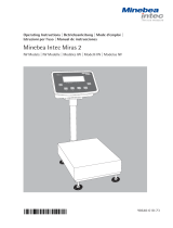
3 Configuring the Device Using the Menu
Fieldbus protocol
e.g., Profibus DP
Fieldbus interface
Interface
protocol
Data in the Minebea Intec indicator
or complete scale
Address area (command no.):
8: gross value
10: tare value
…
Control and status bytes:
Scale control
Write window
min. 2+8 bytes Read window
min. 2+8 bytes
It only describes the data content that is
being exchanged between the master and
slave via the fieldbus protocol (Profibus,
DeviceNet, ModbusTCP).
The interface protocol is below the fieldbus
level and manages access to the
various data through the write and read
windows.

4 Fieldbus / Feldbus Standard Fieldbus / Feldbus Standard 5
Byte 0 Write data: MSB
Byte 1 Write data:
Byte 2 Write data:
Byte 3 Write data: LSB
Byte 4 Read data type request
Byte 5 Write data type
Byte 6 Direct check bits
Byte 7 Direct check bits
4.3 Reading and Writing Data
The amount of data far exceeds the size
of the write/read windows. For this reason,
the parameters are addressed with the
Write data type and Read data type.
The first six bytes of the write window and
the first five bytes of the read window are
required for this. This allows the master to
describe data in the Minebea Intec indica-
tor or complete scale: for example, let’s
say a tare value is supposed to be set to
100 kg. Weights or other data can also be
read by the master from the Minebea Intec
indicator or complete scale. Both the write
and read windows are required for this
operation. A write procedure and a read
procedure ensure a reliable exchange of
parameters.
However, a procedure is not required to
read status bits or write direct control bits.
The general system bits and the status bits
are always present and do not have to be
specifically requested. The direct control
bits are also always available.
Procedure for reading a parameter:
1. Write the type of data/parameter in byte
4 of the write window (e.g., net weight)
as Read data type request.
2. Wait until byte 4 of the read window,
the echo of Read data type request, is
identical to the Read data type request
in byte 4 of the write window.
3. Now the value will be available in bytes
0-3.
Procedure for writing a parameter
with Handshake:
1. Wait until control bit write_handshake
= 0 in the read window.
If this does not occur, delete the bit by
writing a zero (0) in byte 5 of the write
window.
2. Write value in bytes 0–3, if required for
the write data type request.
3. Write the data type request in byte 5.
4. Wait until writehandshake is set in the
read window (Minebea Intec Intec indi-
cator or complete scale confirms receipt
of data).
5. Write 0 in byte 5 of the write window to
delete the “write-handshake” bit in the
read window. If this does not delete the
bit, byte 5 in the write window
cannot be used for writing data.
4.1 Write Window
Data is transferred from the master to the slave (Minebea Intec indicator or complete scale)
in this window. The first four bytes are used to write a data value. The data or parameter
type is described in byte 5.
Byte 4 requests a read value (e.g. net weight readout), which ist received via the read win-
dow. Bits in bytes 6 and 7 are accessed directly regardless of the data type of the write value.
The command is executed after a 0-1 leading edge signal.
4.2 Read Window
Data is transferred from the slave (Minebea Intec indicator or complete scale) to the master
in this window. The first four bytes are used to read a data value. The data or parameter type
is mirrored by the write window in byte 4 when the data is available.
Bits in bytes 6 and 7 are status bits regardless of the data type of the read value.
Byte 0 Read data: MSB
Byte 1 Read data:
Byte 2 Read data:
Byte 3 Read data: LSB
Byte 4 Echo of Read data type
request
Byte 5 General system bits:
writehandshake, power_fail,
analog error...
Byte 6 Status bits
Byte 7 Status bits

6 Fieldbus / Feldbus Standard Fieldbus / Feldbus Standard 7
4.4 Write and Read Window Structure
General structure of the write window for a scale:
Byte Label Description
0 Value to be written (MSB) e.g., fixed tare preset
1 :::
2 :::
3 ::: LSB
4 Read data type e.g., gross value
5 Write data type writes: fixed tare preset
6 bit 7 bit 6 bit 5 bit 4 bit 3 bit 2 bit 2 bit 0 control bits
7 bit 7 bit 6 bit 5 bit 4 bit 3 bit 2 bit 2 bit 0 control bits
General structure of the read window for a scale
Label Description
0 Value to be written (MSB) e.g., gross value
1 ::: e.g., gross value
2 ::: e.g., gross value
3 ::: LSB e.g., gross value
4 Read data type Echo: gross value
5 bit 7 bit 6 bit 5 bit 4 bit 3 bit 2 bit 2 bit 0 control bits
6 bit 7 bit 6 bit 5 bit 4 bit 3 bit 2 bit 2 bit 0 control bits
7 bit 7 bit 6 bit 5 bit 4 bit 3 bit 2 bit 2 bit 0 control bits
5 Data Formats
5.1 Profibus, Modbus
Various data formats were used in the interface description:
DINT Most data values are transferred as a four-byte double-integer value; 32-bit number with sign
Example: write the weight “fixed tare 844”
Write window: byte number 0 1 2 3 4 5 6 7
Value 00 00 03 4C 1F
Example: read negative gross weight -2
Read window: byte number 0 1 2 3 4 5 6 7
Value FF FF FF FE 08
USINT positive 8-bit number. Example: read exponent/unit/scale interval/error
Read window: byte number 0 1 2 3 4 5 6 7
Value 02 04 01 00 04
5.2 DeviceNet
In this fieldbus type the sequence of bytes of data values (byte 0 - byte 3) is reversed.
For values of type DINT (weight values), this problem does not occur, because it is compensated by the firmware.
Order of the bytes 0 ... 3, for example, in the exponent and software version, see table.:
standard sequence sequence DeviceNet
Byte 0 TYPE MSB Byte 0 TYPE LSB
Byte 1 Byte 1
Byte 2 Byte 2
Byte 3 TYPE LSB Byte 3 TYPE MSB

6 Fieldbus / Feldbus Standard Fieldbus / Feldbus Standard 7
All write values are addressed using Write data type_request.
Value in byte 5
Write data type_request Write data to byte 0…3 (parameter)
dec hex
0 0 Has no function, or deletes “write_handshake” bits.
03 3 Lock keypad, incl. ON/OFF key*
04 4 Unlock keypad
31 1F Fixed tare [DINT]
33 21h Sends application initialization data if „Use of application data“ is set
to „Yes“ in the menu.
40 28h Starts an application with the previously sent initialization values (via
21H)
107 6b Start calibration* with ext. factory preset weight
108 6c Stop calibration*
112 70 Set to zero*
113 71 Tare*
114 72 Cancel tare weight*
117 75 Reset power failure bit*
118 76 Tare using the value in the fixed tare preset cache*
119 77 Copy the gross value to the fixed tare preset cache*
121 79 Acknowledge a command error in Cmd_Status byte and resetting the
bit: Ref.-Weight changed (Cmd_Status is part of a read data type)*
157 9dh Describes display if „Use of application data“ is set to „Yes“ in the
menu.
* Write data in bytes 0 to 3 are not required for these types!
Direct check bits (write bits for the fieldbus master)
bit 7 bit 6 bit 5 bit 4 bit 3 bit 2 bit 1 bit 0
Byte 6 Cal-stop Cal-start
Byte 7 Use as Set Reset Cancel tare Tare Set to zero
fixed tare fixed tare power fail
Note:
All control bits react only to a 0 -> 1 switch.
A state must last for at least 100 ms before a switch will be recognized.
Cal-Stop stop calibration with „default weights“
Cal-Start start calibration with „default weight“
Use as fixed tare writes the current gross value into the fixed tare memory
Set fixed tare tares the scale with the value in the fixed tare memory
Reset powerfail causes power-fail flag in the slave’s read data to be reset
Cancel tare weight cancels the tare weight on the scale
Tare tares the scale
Set to zero sets the scale to zero if the weight is within the zero-setting range
6 All Write Data

8 Fieldbus / Feldbus Standard Fieldbus / Feldbus Standard 9
All read values are addressed by Read data type_request
Value in byte 4
Read data type_request Read data in byte 0…3 (parameter)
dec hex
1 01 IndStatus/ADUstatus/CmdStatus/Activs [USINT]
4 04 Exponent/Unit/Scale interval/LastError [USINT]
5 05 Version information for Minebea Intec indicator
(control unit) (see below)
6 06 Serial number of scale [DINT]
8 08 Gross [DINT]
9 09 Net [DINT]
10 0A Tare [DINT]
14 0E Scale end value [DINT]
31 1F Fixed tare (value in tare memory) [DINT]
190 BE Reference weight of applications Counting, percentage
weighing, neutrality measurement [FLOAT4]
Direct conrol bits (to be read from the fieldbus master)
bit 7 bit 6 bit 5 bit 4 bit 3 bit 2 bit 1 bit 0
Byte 5 Write Ref.-Weight
changed
hand-shake Power fail
Byte 6 Command Cmd-error Tare Calibr.
active active active
Byte 7 Outside Stability Inside 1/4 d range Below Large Over scale Scale error
adjustment zero-setting zero overload end value
range
Write handshake: 0 = Minebea Intec indicator (conrol unit) or complete scale is ready to receive new write values
Power fail: Power to scale was interrupted (this signal must be reset using either the “Reset power fail” bit or the Write data
type 0+75 hex.)
Tare active: Scale is tared
Calibration active: Scale is being calibrated/adjusted or the unit was changed; the exponent has changed, scale has been switched
Outside adjustment: The scale is between the scale end value and overload; if the W&M mode is active, then also when weight < 0
Stability: The scale is stable
Inside zero-setting range: Scale is within zero-setting range
Below zero: The scale is below zero
Large overload: The scale is loaded beyond the overload range
Over scale end value: Scale is above scale end value to the point at which “H” is displayed (maximum scale range of e.g., 5000 kg)
Scale error: Scale is in error state, e.g., ‘err 54’. The read data (weight values) in bytes 0-3 are then invalid.
Terminal is OFF, menu active, display shows “L” or “H”, no scale connected.
Cmd error: After every write cycle, the parameter is checked for validity, or if it is an action, it is checked for feasibility.
If the parameter is invalid, or the action cannot be performed, the bit will be set, and the parameter
will be ignored.
The bit can be reset using the Write data type 0+79 hex.
Command active: The requested action is still active (e.g., the scale is waiting for stability after receiving a tare command).
Ref. Weight changed: If the application is read out or re-initialized, the bit is set. With the command 0x79 = acknowledge a
CMD errors, the bit can be deleted.
7 All Read Data

8 Fieldbus / Feldbus Standard Fieldbus / Feldbus Standard 9
8.1 Weight
To read weights, just write the desired weight type to byte 4 of the write window (Read data type_requirement). When the weight is available,
the type will be returned in byte 4 of the read window. If the weight request is not cleared, the byte will always be updated to the last weight
recorded.
Example: gross value
Write window: byte number 0 1 2 3 4 5 6 7
Value 08
Read window: byte number 0 1 2 3 4 5 6 7
Value 00 00 11 B4 08
The numerical value (11B4h = 4532 dec.) is read out to the display without units or commas. These can be requested using read data type 04.
Negative values are shown as a twos complement.
Example: Negative weight -12
Read window: byte number 0 1 2 3 4 5 6 7
Value FF FF FF F4 08
8.2 Exponent, Unit, Scale Interval
The exponent, weight unit and scale interval must always be read out when the “calibrate-active bit” is set and before the first weight is
requested. This is because the unit or weighing range may have changed.
They can be read using type 4.
Write window: byte number 0 1 2 3 4 5 6 7
Value 04
Read window: byte number 0 1 2 3 4 5 6 7
Value 02 03 02 00 04
The first individual bytes have the following meanings:
Byte 0: Exponent: Valid range 0-7.
0 = 0000 no decimal point
1 = 000.0
2 = 00.00
3 = 0.000
Byte 1: Unit: Valid numbers 1-15 (Minebea Intec Hamburg GmbH)
and 128-147 (Minebea Intec only)
1 = mg 128 = user-defined unit 139 = pennyweight
2 = g 131 = carat 141 = parts per pound
3 = kg 133 = ounce 142 = Chinese taels
4 = t 134 = Troy ounce 143 = momme
5 = lb (pound) 135 = Hong Kong taels 144 = Austrian carat
6 = L (liter) 136 = Singapore taels 145 = tola
7 = seconds 137 = Taiwanese taels 146 = baht
15 = percent 138 = grain 147 = mesghal
Byte 2: Scale interval Indexed to a table as follows:
1 → Interval 1
2 → Interval 2
3 → Interval 5
4 → Interval 10
5 → Interval 20
6 → Interval 50
The calculated weight results from the DINT value and exponent as follows:
Weight = (number in byte 0–3)DINT *10(-Exponent)
Therefore, the weight from the previous example is equal to: 45.32 kg with scale interval 2.
8 Read Weights

10 Fieldbus / Feldbus Standard Fieldbus / Feldbus Standard 11
In addition to the write data types mentioned above, individual bits in byte 7 of the write window are also assigned to performing scale
functions such as taring or setting to zero. The desired function is performed by a 0-1 leading edge signal at the corresponding bit.
Function of bits in write byte 7
Bit 7 writes the current gross value to the fixed tare cache (saving only, no taring)
Bit 6 tares the scale with the value in the fixed tare cache
Bit 5 resets power failure flag as an acknowledgement of a power failure
Bit 4 no function
Bit 3 no function
Bit 2 cancels the tare (deletes tare memory)
Bit 1 tares the scale with the current weight
Bit 0 sets the scale to zero if the weight is within the zero-setting range
Example:
If the scale is within the zero-setting range, this function is carried out once:
Write window: Byte number 0 1 2 3 4 5 6 7
Value 01
10 Initializing Applications
An application can be initialized using additional application data from the interface protocol. To use this feature, the „Use of application
data“ option must be activated in the menu. This option attaches additional data to the standard 8-byte protocol (scale interface).
However, the application or combination of applications to be initialized must first be configured in the Scale menu.
Example: one scale plus application data (34 bytes):
Scale interf. | Application data range
0 | 1 | 2 | 3 | 4 | 5 | 6 | 7 | 0 | 1 | 2 | 3 | 4 | 5 | 6 | 7 | 8 | 9 | 10 | 11 | 12 | 13 | 14 | ....
Example: two scales plus application data (34 bytes):
1st scale | 2nd scale | Application data range
0 | 1 | 2 | 3 | 4 | 5 | 6 | 7 | 0 | 1 | 2 | 3 | 4 | 5 | 6 | 7 | 0 | 1 | 2 | 3 | 4 | 5 | 6 | 7 | 8 | 9 | 10 | 11 | ....
Initializing an application: „Checkweighing“:
The first application data byte is located directly behind the data of the scale interface.
Byte 0-3 (of the application data range): target value (UInt32)
Byte 4-7 (of the application data range): lower limit as an absolute value (UInt32)
Byte 8-11 (of the application data range): upper limit as an absolute value (UInt32)
Application ID and command to initialize the above limits are set in the scale interface of the active scale (numbering starting with 0):
Byte 2 (of the scale interface): 0x04 // ID for checkweighing
Byte 5 (of the scale interface): 0x21 // command for sending initialization data
Initializing an application: „Counting“ or „Neutral measurement“ or „Weighing in percent“:
The first application data byte is located directly behind the data of the scale interface.
Byte 0-3: specific piece weight (UInt32)
9 Taring and Setting to Zero

10 Fieldbus / Feldbus Standard Fieldbus / Feldbus Standard 11
Application ID and command to initialize the above piece weight are set in the scale interface of the active scale (counting starting with 0):
Byte 3: 0x01 // ID for Counting or Neutral measurement or Weighing in percent
Byte 5: 0x21 // command for sending initialization data
The possible number of decimal places for the piece weight is based on that of the scale. If the scale has three decimal places, a piece weight
of 0.123 grams can be selected, for example. The selected piece weight is also rounded according to the scale interval. Command 0x28h is
written to byte 5 so that the application can be restarted using these new initialization data.
Example:
A scale using the gram unit,
„Checkweighing“ application: target value 130 g, lower limit 102 g, upper limit 135 grams
Scale interface | Application data range
0 | 1 | 2 | 3 | 4 | 5 | 6 | 7 | 0 | 1 | 2 | 3 | 4 | 5 | 6 | 7 | 8 | 9 | 10 | 11 | 12 | ...
0 0 4 0 0 21 0 0 0 0 0 82 0 0 0 66 0 0 0 87 0 0 ...
Example:
A scale with two decimal places using the gram unit,
„Counting“ application: piece weight 1.15 grams
Scale interface | Application data range
0 | 1 | 2 | 3 | 4 | 5 | 6 | 7 | 0 | 1 | 2 | 3 | 4 | 5 | ...
0 0 0 1 0 21 0 0 0 0 0 73 0 0 0 ...
Application start with the new initialization data:
Scale interface | Application data range
0 | 1 | 2 | 3 | 4 | 5 | 6 | 7 | 0 | 1 | 2 | 3 | 4 | ...
0 0 0 0 0 28 0 0 0 0 0 0 0 ...
If parallel applications „Counting“ and „Checkweighing“ are active. Initialization of both applications:
The first application data byte is located directly behind the data of the scale interface.
Byte 0-3: specific piece weight (UInt32) in the currently active unit
Byte 4-7: target value (UInt32) in unit: piece
Byte 8-11: lower limit as an absolute value (UInt32) in unit: piece
Byte 12-15: upper limit as an absolute value (UInt32) in unit: piece
Application ID and command to initialize the above limits are set in the standard scale interface of the active scale
(numbering starting with 0):
Byte 2: 0x04 // ID for Checkweighing
Byte 3: 0x01 // ID for Counting
Byte 5: 0x21 // command for sending initialization data
Command 0x28h is written to byte 5 so that the applications can be restarted using the new initialization data.
Example:
A scale with two decimal places and using the gram unit,
„Counting“ application: piece weight 1.15 grams
„Checkweighing“ application: target value 130 pieces, lower limit 102 pieces, upper limit 135 pieces
Scale interface | Application data range
0 | 1 | 2 | 3 | 4 | 5 | 6 | 7 | 0 | 1 | 2 | 3 | 4 | 5 | 6 | 7 | 8 | 9 | 10 | 11 | 12 | 13 | 14 | 15 | 16 |...
0 0 4 1 0 21 0 0 0 0 0 73 0 0 0 82 0 0 0 66 0 0 0 87 0 ...
Application start with the new initialization data:
Scale interface | Application data range
0 | 1 | 2 | 3 | 4 | 5 | 6 | 7 | 0 | 1 | 2 | 3 | 4 | ...
0 0 0 0 0 28 0 0 0 0 0 0 0 ...
You can determine whether or not the initialization or restart was successful using the „Cmd error“ bit in byte 6 of the read window.
The command was successful if the bit is zero.

12 Fieldbus / Feldbus Standard Fieldbus / Feldbus Standard 13
Similar to application initialization, you can also describe parts of the display using the application data range.
The display area to be described is selected in byte 3 of the scale interface. Additional control bits can be issued in byte 2.
The first application data byte is located directly behind the data of the scale interface.
Byte 0-31: Display string to be shown (ASCII characters in hex code)
Option bits and command settings for writing to the display in the scale interface:
Byte 2: control bits:
0x04: activates the beeper when writing to the display
0x02: represents the received string inversely. Only used in combination with 0x01 and Combics 3
0x01: writes received string to the display, if not set, returns control to the scale control unit
Byte 3: for describing a window in the display:
0x1d: application display, line 1 (Combics 3 only)
0x9D: application display, line 2 (Combics 3 only)
0x13: main display (7 characters), only used with unverified control units
Byte 5: activation command:
0x9D: applies the above display string and control instructions
Please note: when you write to one of the application lines for the first time, the contents of both lines will be overwritten and/or deleted.
Example:
Describing application line 1 for a Combics 3 with string: „Minebea Intec“ with an inverse format
Scale interface | Application data range
0 | 1 | 2 | 3 | 4 | 5 | 6 | 7 | 0 | 1 | 2 | 3 | 4 | 5 | 6 | 7 | 8 | 9 | 10 | 11 | 12 | 13 | 14 | 15 | 16 |...
0 0 3 1d 0 9d 0 0 53 61 72 74 6f 72 69 75 73 0 0 ...
Example:
Return control of application line 1 for a Combics 3 to Combics:
Scale interface | Application data range
0 | 1 | 2 | 3 | 4 | 5 | 6 | 7 | 0 | 1 | 2 | 3 | 4 | 5 | 6 | 7 | 8 | 9 | 10 | 11 | 12 | 13 | 14 | 15 | 16 |...
0 0 0 1d 0 9d 0 0 0 0 0 0 0 ...
Example:
Writing to the main display of the control unit with string: „key“
Scale interface | Application data range
0 | 1 | 2 | 3 | 4 | 5 | 6 | 7 | 0 | 1 | 2 | 3 | 4 | 5 | 6 | 7 | 8 | 9 | 10 | 11 | 12 |...
0 0 1 13 0 9d 0 0 54 61 73 74 65 0 0 0 ...
12 Read the reference piece weight
The reference piece weight is output in the FLOAT4 format (IEEE 754). No piece weight can be provided since e.g. the application is not acti-
vated , the value “not a number” (NAN) is output with the hex value: 0x7F 0x80 0x00 0x01.
The output reference piece weight has the unit which is active at the time of initialization of the application and refers to 1 piece (e.g., kg /
piece).
Example: The application is initialized in “kg”. If the unit is switched to “g”, nothing will change at the read ref. Piece weight! But about that
“Calibrate Active bit indicates that the unit has changed and can read it,
11 Describing the Display

12 Fieldbus / Feldbus Standard Fieldbus / Feldbus Standard 13
There are three different types of errors:
– scale errors (indicator, hardware error)
– command errors
– adjustment errors
Scale errors are displayed to the master via bit 0 (scale error) in
byte 7 of the read data check bits. The master can then read out
the IndStatus and ADU-Status bytes with read data type request
01 if the error needs to be specified more precisely. Scale errors
do not affect the LastError byte!
The “scale error” bit and bit 0 in IndStatus identify all fatal errors
and hardware errors in the scale and indicator.
The “scale error” bit is set for as long as the error exists in the
scale and is automatically reset by the indicator. It also indi-
cates scale states in which no weigh data can be sent; e.g. menu
active; “L” or “H” displayed; indicator off.
Command and adjustment errors are displayed to the master via
bit 6 in byte 6 of the read data check bits. The master can then
read out the LastError byte with read data type request 04h and
specify the exact error using the error number filed here. The
error numbers are company-specific.
Once command and calibration errors occur, they are displayed
to the master (bit 6 in byte 6 of the read data check bits) until
the master acknowledges them via the write data type request
79h and they are no longer occurring.
It is of no significance whether the error is only temporary.
If several errors occur simultaneously and the master is unable
to read out the exact reason for the error, the last error that
occurred will always be displayed to the master. An error history
is not created!
12.1 Status Bytes
If the master has detected a scale or command (calibration) error,
the error can be specified more exactly, if necessary, using a read
data type request 01.
The following bytes are then read:
IndStatus:
Scale state
Bit 0 Fatal scale error
Bit 1 Gross weight > scale end value = max. load
Bit 2 Scale is overloaded
Bit 3 Gross weight < zero
Bit 4 The scale is at the zero point, 4 interval
Bit 5 Gross weight is inside the zero-setting range
Bit 6 Scale is stable
Bit 7 Gross weight is outside the scale
When bit 0 is set, the scale error in the AduStatus byte is speci-
fied more exactly, if possible.
12 Error Handling
ADUstatus:
State of A/D converter
Bit 0 Weight too low (ERROR 54)
Bit 1 Weight too high (ERROR 55)
Bit 2 Arithmetic error (overflow)
Bit 3 Input offset
Bit 4 Reserved
Bit 5 Reserved
Bit 6 No scale connected
Bit 7 Indicator is off
If one of the bits 0-3 is set, Bit 0 in the IndStatus byte must also
be set.
CmdStatus:
Status of command execution
Bit 0 Error during execution of action (cmdError),
can be read out from the LastError (see below) byte.
Identifies command and calibration errors
Bit 1 Action is being carried out, in the execution phase
Bit 2 Power failure, set at each power-on and reset by the
master via command 75h.
Bit 3 Reserved
Bit 4 Reserved
Bit 5 Reserved
Bit 6 Reserved
Bit 7 Reserved
Activs:
Actions in progress:
Bit 0 Reserved
Bit 1 Device is in calibration mode
Bit 2 Device is tared
Bit 3 Reserved
Bit 4 Reserved
Bit 5 Reserved
Bit 6 Reserved
Bit 7 Reserved
12.2 Command and Adjustment Errors Possible
One of many functions the read data type request 04 can perform is
reading the “Last Error” byte, which describes the current command
or calibration error:
ID number Meaning
of command error
2 hex Zero point error during cal start:
not tared, or scale under load
5 hex Manual cal. weight not at end position
7 hex Function or command invalid for calibrating
scales (calibration switch off)
8 hex Zeroing error at gross wt. > zeroing range
9, 11 hex Tare error at gross wt. <= 0

14 Fieldbus / Feldbus Standard Fieldbus / Feldbus Standard 15
Up to three scales can be connected to a Minebea Intec control
unit. Therefore, the size of the read and write window can be 1+8,
2+8 or 3+8 bytes. The first 8 bytes represent the 1st scale, the
next 8 the 2nd scale, etc.
Example: write window
Address Scale number Input area
0000 hex 1 Value to be written (MSB)
0001 1 :::
0002 1 :::
0003 1 ::: (LSB)
0004 1 Read data type
0005 1 Write data type
0006 1 Check bits
0007 1 Check bits
0008 2 Value to be written (MSB)
0009 2 :::
000A 2 :::
000B 2 ::: (LSB)
000C 2 Read data type
000D 2 Write data type
000E 2 Check bits
000F 2 Check bits
Only one scale can be accessed at any given time; therefore, the
entire write area of the inactive scale should be filled with zeroes.
If a number other than zero is entered in bytes 4-7 of the write
area for the inactive scale, this will cause the indicator to constantly
switch back and forth between scales until a write data type is
received for the scale that is currently inactive.
If a write or read data type request is written to the write area
of both scales while only one scale is active, the command for the
active scale will be executed first. After a scale switch, the com-
mand will then be executed on the second scale. The protocol then
switches back and forth between the two scales continuously.
13 Operation Using Several Platforms

14 Fieldbus / Feldbus Standard Fieldbus / Feldbus Standard 15
14 Profibus interface
If you have selected „Data communication Profibus“ in the menu
for UniCom, you have the option to configure the following menu
settings:
[Profibus address]:
You can select the network address (0-126) here.
Factory setting: 126
[Use of application data]:
You can select yes or no here.
If you select yes, the scale-specific data range is expanded by 34
bytes, e.g. for initializing applications.
Factory settings: No
The control unit automatically detects the Profibus’ baud rate. All
relevant baud rates up to 12 Mbaud are possible here.

16 Fieldbus / Feldbus Standard Fieldbus / Feldbus Standard 17
15 DeviceNet-interface
If you have selected „Data communication DeviceNet“ in the menu
for UniCom, you have the option to configure the following menu
settings:
[MAC ID]:
Here, you can select the MAC ID (network address) in the range
from 1 to 62.
Factory setting: 62
[Baud rate]:
Selecting Bus baud rates: 125k, 250K or 500K bps are possible.
Default setting: 125k
[Using Quick connect]:
The Quick connect function can be activated here.
Default setting: NO
[Using application data]:
Here, the scale-specific data range is expanded by 34 bytes, e.g. for
initializing applications.
Factory settings: NO
The interface functions as a slave in Poll mode.

16 Fieldbus / Feldbus Standard Fieldbus / Feldbus Standard 17
Enter the required numbers in the
UNICOM menu under Ethernet > Source
IP, Ethernet > ListenPort, etc. Under
“Source name” you can enter letters and
numbers. Enter up to 15 characters.
Port numbers
Range: 0 – 65535
Because many of the ports up to 49150
are already allocated, we recommend using
numbers higher than 49150.
This does not apply for Modbus/TCP,
as port number 502 is used here (see the
operating instructions for the field bus
module). Profibus/ Ethernet Interface:
Initialization
14.1 Display: Initialization Completed
Once initialization of the Ethernet or Pro-
fibus module has been completed success-
fully, the display shows “=”.
Network module initialized
=
If initialization was not successful, no
symbol is displayed. The symbol does not
indicate whether or not a network connec-
tion is active.
TCP Connections:
In the SBI C/S operating mode, the Com-
bics breaks the connection automatically.
In other operating modes; e.g.,
SBI Serv, SMA, xBPI or Modbus/TCP, the
connection remains active until the com-
puter (client) disconnects it. Only one con-
nection can
be active at any given time.
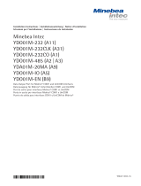
Combics 3: Initialization
Once initialization of the
Ethernet or Profibus module
has been completed successfully,
the symbol shown here is dis-
played continuously. When this
symbol is shown, the initializa-
tion has been completed and the
device is ready for operation.
This symbol does not indicate
whether or not a network
connection is active.
9
16 Ethernet Interface
14.2 Ethernet Interface: Features
Source IP: IP address of the Combics indicator
If the address 0.0.0.0 is selected, an IP address should be allocated
dynamically by a DHCP server.
Source name: This parameter is alternative to the “Source IP“ address. You can enter a
name of up to 15 characters for identification of the Combics. The name is
passed to the domain name system (DNS) server if:
– an IP address has been entered under DNS IP,
or
– an IP address has been allocated by a DHCP server.
Device port: Port number on which the Combics listens for server operation.
Subnet mask: IP address mask for activating addresses in a subnet. If the mask is allocated
by a DHCP server, enter 0.0.0.0 here.
Gateway IP: IP address of the gateway
This is for addressing a server using the Target IP field when the server is in
another network.
If the IP address is allocated by a DHCP server, enter 0.0.0.0 here.
DNS IP: To address a DNS server explicitly, enter the IP address of that server.
If the address 0.0.0.0 is selected, the address will either be allocated by
a DHCP server or ignored.
Target IP: Address of the server that receives data from the Combics.
This is important when the Combics is operating as client in SBI C/S mode
and automatic data output is active. If you are using UDP, an address must
be entered here.
Target port: Number of the port over which the server with the target IP receives data
from the Combics.
Protocol: Select the transport protocol for transmitting data over Ethernet.
You can choose from the following:
– TCP: connection oriented; high data security
– UDP: connection independent (does not work with Modbus/TCP)
Mode: Select the format that contains the user data embedded in TCP or UDP (SMA,
for example, is tunneled with TCP or UDP over Ethernet when using TCP or
UDP) which makes the entire range of SMA functions also available over Eth-
ernet. The same applies for SBI C/S und XBPI).
When using the SBI Serv, XBPI or SMA and Modbus/TCP protocol, Combics
operates exclusively as server. If SBI C/S is used, the Combics is both server
and client.
The Combics acts as client when it actively builds up a connection to the
server (i.e., to the PC); for example, when the p [Print] key is pressed or
when automatic data output is active; for other operations, the Combics acts
as server.
In SBI Serv mode, data can be sent to the client (i.e., to the PC) by pressing
the p [Print] key if the client has built up a connection to the Combics
(i.e., to the server).
Power-up
response: If the interface module is active, the display may take up to 20 seconds lon-
ger to respond.

18 Fieldbus / Feldbus Standard Fieldbus / Feldbus Standard 19
15.1 Intended Use: Modbus/TCP
The Modbus protocol was developed
for data transmission with controllers
from the Modicon company (now called
Schneider Electric). Data is transmitted
in the form of 16-bit registers (integer
format) or as status information in the
form of data bytes. The protocol has
been expanded since its initial develop-
ment and is used with devices from
other manufactures as well. New data
types have been added, in particular to
obtain better resolution for the values
transferred.
In adapting the Modbus protocol for
new media, deriviative protocols such
as Modbus Plus and Modbus/TCP were
created.
To preserve compatibility, the basic
structure of the data area and address-
ing mechanisms has been retained.
The following descriptions apply to the
Modbus/TCP protocol and is restricted
to the functionality of this protocol in
Minebea Intec devices.
! Once Modbus/TCP has been selected,
the selection of TCP or UDP in the
operating menu of the Minebea Intec
display and control unit has no effect;
TCP is always active.
15.2 Structure of Messages
The application data unit (ADU) in
Modbus/TCP consists of the following
blocks:
MBAP header Function code Data
7 bytes 1 Byte n bytes
MBAP header = Modbus application
protocol header
Bytes 0, 1: Transaction identifier:
identification during multiple simulta-
neous active requests.
Bytes 2, 3: Protocol identifier:
always 0 (Modbus protocol)
Byte 4: Number of subsequent data
bytes (high byte): always 0 (because all
messages are shorter than 256 bytes)
Byte 5: Number of subsequent data
bytes (low byte)
Byte 6: unit identifier (previously called
“device address“). Because the devices
are addressed by their IP address, this
parameter has no function and should
be set to 0xFF. Exception: for com-
munication over a gateway, the device
address is set in the same manner as
was previously used.
Function code
Byte 7: Function code of the standard
Modbus protocol.
Data
Bytes 8 to n: The data area corresponds
to that of the standard Modbus protocol.
The CRC checksum is not used, however,
because it is implemented on the TCP/
IP protocol level.
The content and structure of this data
corresponds to the Minebea Intec Stan-
dard Scale Interface as described in
Chapters 4 through 9.
15.3 Communication Management
Modbus communication requires that
a TCP connection is established
between a client (e.g., a computer) and
the server (Minebea Intec indicator or
complete scale). The TCP port 502,
reserved for Modbus, is generally used
for this connection. The operator can
configure a different port if desired.
Keep in mind that if a different port is
configured, communication is no longer
possible over port 502.
If there is a firewall between server and
client, make sure the port selected has
access across the firewall.
15.4 Functionality
The following Modbus functions are
implemented in Minebea Intec indica-
tors and complete scales:
Function 03 hex: Read continuous
words (2 bytes)
Function 10 hex: Write continuous
words (2 bytes)
Function 08 hex: Diagnostics; sub-
function 0000 hex
15.5 Error Handling
! In the event of transmission error (e.g.,
device not found; device is switched
off) the server (Minebea Intec indicator
or complete scale) does not send confir-
mation to the client. This causes a client
timeout.
In the event of error, the server sends an
error message to the client.
Device response:
MBAP header Function code Data
Copy Code+80H Error
of request code
The functions code received is copied
and the highest bit (MSB) is set.
The error code indicates an operating
error or program error. The following
error codes are supported:
Error code Meaning
01 hex Unknown function number
02 hex Invalid address
03 hex Incorrect data format
(e.g., data written exceeds
quantity specified)
04 hex Server error; e.g., invalid
message length
06 hex Server busy; e.g., server is
still processing the previous
message
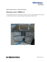
17 Standard Scale Interface with Modbus/TCP
Network Access
Ethernet II and 802.3 layer
IP
IQVP
TCP
Modbus
Mag
APP

18 Fieldbus / Feldbus Standard Fieldbus / Feldbus Standard 19
15.6 Fundamentals
The Modbus/TCP protocol is used as a frame, while the data transmitted conforms to the Minebea Intec Standard Scale Interface protocol
(see Chapters 4 through 10).
Before data in the scale can be loaded in the PC, a request must be sent to the scale specifying the desired data (e.g., gross weight value).
After this request, for example, Modbus commands can be used to read the gross value.
To request the gross weight value, the following must be written in register 24. The data to be read is structured as a data window
(see Chapter 4), and “08“ is entered as the type of data to specify the gross weight value.
The gross value can now be read. The following is read in register 00. The data received is structured as a data window (see Chapters 4 and 7).
It includes the requested gross weight value and additional status information.
From this point on, the gross weight value is displayed each time the 00 register is read.
To read a different value; for example, the exponent of the weight value, the following must be written in register 1024. After this is written,
the exponent can be read in register 00.
Only these two registers are used (1024 for writing and 00 for reading). The ‚read‘ and ‚write‘ windows in the data area of the Modbus
protocol are used for control and reading of data from the scale.
15.7 Diagnostics
Function 08 hex
Sub-function 00 tests whether a particular device is connected. The message sent is returned with alteration.
Client (computer) server (Minebea Intec indicator or complete scale)
Transaction Protocol Number of Unit Data
identifier identifier data bytes identifier Funct. Sub-function Data
0x00 tno 0x00 0x00 0x00 0x06 0xff 0x08 0x00 0x00 High byte Low byte
Response: Server (Minebea Intec indicator or complete scale) client (computer)
Transaction Protocol Number of Unit Data
identifier identifier data bytes identifier Funct. Sub-function Data
0x00 tno 0x00 0x00 0x00 0x06 0xff 0x08 n High byte Low byte
Send: 00 00 00 00 00 06 ff 08 00 00 CC 33
Response: 00 00 00 00 00 06 ff 08 00 00 CC 33
15.8 Standard Scale Interface
Control is implemented over the same standard scale interface used by Minebea Intec equipment for other fieldbuses; e.g., Profibus (see Chap-
ters 4 through 9), and references the data area of the MODBUS protocol.
There is a ‘read‘ window and a ‘write‘ window; both are at least 8 bytes (4 words) wide. If a second weighing instrument is configured,
the width is increased to 16 bytes (8 words). These windows are the data area which is embedded in the Modbus protocol frame.
‘Write’ window for a weighing instrument in the standard scale interface:
Register 1024 dec Register 1025 dec Register 1026 dec Register 1027 dec
Byte 0 Byte 1 Byte 2 Byte 3 Byte 4 Byte 5 Byte 6 Byte 7
Write value Read data Write data Control_ Control_
type type Byte1 Byte2
“Registers“ are used to address data in the Modbus protocol.
To communicate with a second weighing instrument, use registers 1028 through 1031 dec.
Writing data on the server (Minebea Intec indicator or complete scale):
Function code: 10 hex
Before data can be read over the Modbus interface using the 03 Hex function, the function 10 Hex must be invoked to send data to the
server (Minebea Intec indicator or complete scale) in the form of a “write” window.
The same applies when setting control bits or sending a write-data type to the server (Minebea Intec indicator or complete scale).
This function code enables you to switch between scales. For this purpose, bytes 4-7 must have an input in register 1028.

20 Fieldbus / Feldbus Standard Fieldbus / Feldbus Standard 21
Example: request net weight value:
Client (computer) server (Minebea Intec indicator or complete scale)
Transaction Protocol Number of Unit Data
identifier identifier data bytes identifier Funct. Start No. Bytes Data
address register
0x00 tno 0x00 0x00 0x00 n+7 0xff 0x10 High Low High Low n ‚Write‘
byte byte byte byte window
Response: Server (Minebea Intec indicator or complete scale) client (computer)
Transaction Protocol Number of Unit Data
identifier identifier data bytes identifier Funct. Start address No. register
0x00 tno 0x00 0x00 0x00 0x06 0xff 0x10 High Low High Low
byte byte byte byte
tno = transaction number, defined by client
Example:
Send: 00 00 00 00 00 0F FF 10 04 00 00 04 08 00 00 00 00 08 00 00 00
Response: 00 00 00 00 00 06 FF 10 04 00 00 04
‚Read‘ data window for a weighing instrument in the standard scale interface:
Register 0 dec Register 1 dec Register 2 dec Register 3 dec
Byte 0 Byte 1 Byte 2 Byte 3 Byte 4 Byte 5 Byte 6 Byte 7
Read data Echo read- Status Status Status
data type request byte 1 byte 2 byte 3
„Registers“ are used to address data in the Modbus protocol.
To communicate with a second scale, use registers 4 through 7.
Reading data from the server (Minebea Intec indicator or complete scale)
Function code: 03 hex
Client (computer) server (Minebea Intec indicator or complete scale)
Transaction Protocol Number of Unit Data
identifier identifier data bytes identifier Funct. Start No.
address register
0x00 tno 0x00 0x00 0x00 0x06 0xff 0x03 High Low High Low
byte byte byte byte
Server (Minebea Intec indicator or complete scale) client (computer)
Transaction Protocol Quantity Unit Data
identifier identifier data bytes identifier Funct. No. of data Data
bytes
0x00 tno 0x00 0x00 0x00 n+3 0xff 0x03 n ‚Read‘ window
Example:
Send: 00 00 00 00 00 06 FF 03 00 00 00 04
Response: 00 00 00 00 00 0B FF 03 08 00 00 00 32 08 40 20 70
/