SICK Alignment bracket Mounting instructions
- Typ
- Mounting instructions


Alle Rechte vorbehalten. Irrtümer und Änderungen vorbehalten.
1 Zu diesem Dokument
Dieses Dokument gilt für die Ausrichthalterung mit der Artikelnummer 2116913.
2 Produktbeschreibung
Mit der optionalen Ausrichthalterung kann ein sicherer Mehrstrahlscanner an einem
Ma
schinen- oder Profilrahmen montiert und ausgerichtet werden.
Die Ausrichthalterung ermöglicht eine vertikale Neigung des sicheren Mehrstrahlscan‐
ners um bis zu ± 10°.
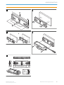
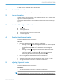
3 Überblick über die Ausrichthalterung
Überblick:
A
!
Befestigungsbohrungen
"
Seitliche Längsbohrungen
§
Zentrierbohrungen
$
Kreuzschlitzschrauben zur Fixierung des Neigungswinkels
%
Skala Neigungswinkel
4 Ausrichthalterung montieren
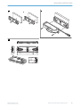
Maßzeichnung Ausrichthalterung:
E
Vorgehensweise
1.
Die Ausrichthalterung an einen Maschinen- oder Profilrahmen montieren.
a) Montagevariante 1 (
B ): Die A
usrichthalterung mit M5-Schrauben über die
seitlichen Längsbohrungen an einen Maschinen- oder Profilrahmen montie‐
ren.
Auf jeder Seite mindestens eine Längsbohrung zur Befestigung der Ausricht‐
halterung verwenden.
b) Montagevariante 2 (
C ): Mit einer S
enkschraube über eine der Zentrierboh‐
rungen die Ausrichthalterung um die Achse der Senkschraube drehen und
an einem Maschinen- oder Profilrahmen fixieren (!). Die Ausrichthalterung
anschließend mit M5-Schrauben über die seitlichen Längsbohrungen montie‐
ren (").
2. Die M5-Schrauben mit niedrigem Kopf und Unterlegscheibe (maximale Dicke:
1,2 mm) verwenden.
3. Mindestlänge der M5-Schrauben und Senkschrauben: 12 mm.
4. Minimale Einschraubtiefe der M5-Schrauben und Senkschrauben: 10 mm.
5. Anzugsdrehmoment für M5-Schrauben und Senkschrauben: 4,5 Nm … 5,0 Nm.
✓
Die Ausrichthalterung ist an einem Maschinen- oder Profilrahmen montiert.
5 Ausrichthalterung ausrichten
Maßzeichnung Ausrichthalterung:
E
Voraussetzungen
•
Die A
usrichthalterung ist an einem Maschinen- oder Profilrahmen montiert.
MONTAGEANLEITUNG
8026155/2021-02-04 | SICK M O N T A G E A N L E I T U N G | Alignment bracket
3
Irrtümer und Änderungen vorbehalten

HINWEIS
U
m die Befestigungsschrauben bei starken Vibrationen zu sichern, ein Schraubensiche‐
rungsmittel verwenden.
Vorgehensweise
W
enn die Ausrichthalterung vor der Montage des sicheren Mehrstrahlscanners ausge‐
richtet wird:
1. Den Neigungswinkel des beweglichen Teils der Ausrichthalterung einstellen,
A ,
%. Die A
usrichthalterung kann um bis zu ± 10° geneigt werden.
2.
Den eingestellten Neigungswinkel über die Kreuzschlitzschrauben fixieren,
A , $.
Anzugsdrehmoment der Kreuzschlitzschrauben: 0,4 Nm … 0,5 Nm.
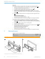
3. Den sicheren Mehrstrahlscanner auf die Ausrichthalterung setzen, sodass die
Be
festigungsbohrungen des sicheren Mehrstrahlscanners auf den Gewindeeinsät‐
zen der Ausrichthalterung liegen,
D .
4.
Den sicheren Mehrstrahlscanner mit 2 M5-Schrauben an die Ausrichthalterung
montieren,
D .
M5-Schrauben mit niedrigem Kopf verwenden.
Empfohlene Schraubenlänge: 20 mm.
Anzugsdrehmoment der M5-Schrauben: 4,5 Nm … 5 Nm.
✓
D
er sichere Mehrstrahlscanner ist auf der Ausrichthalterung montiert und ausge‐
richtet.
Wenn die Ausrichthalterung nach der Montage des sicheren Mehrstrahlscanners aus‐
gerichtet wird:
1. Den sicheren Mehrstrahlscanner auf die Ausrichthalterung setzen, sodass die
Befestigungsbohrungen des sicheren Mehrstrahlscanners auf den Gewindeeinsät‐
zen der Ausrichthalterung liegen,
D .
2.
Die 2 M5-Schrauben in den Befestigungsbohrungen zunächst leicht anziehen.
M5-Schrauben mit niedrigem Kopf verwenden.
3. Den Neigungswinkel des beweglichen Teils der Ausrichthalterung einstellen,
A ,
%. Die A
usrichthalterung kann um bis zu ± 10° geneigt werden.
Die 2 M5-Schrauben in den Befestigungsbohrungen fest anziehen.
Empfohlene Schraubenlänge: 20 mm.
Anzugsdrehmoment der M5-Schrauben: 4,5 Nm … 5 Nm.
✓
D
er sichere Mehrstrahlscanner ist auf der Ausrichthalterung montiert und ausge‐
richtet.
6 Bestelldaten
Bestelldaten Ausrichthalterung
Artikel Artikelnummer
Ausrichthalterung 2116913
MONTAGEANLEITUNG
4
M O N T A G E A N L E I T U N G | Alignment bracket 8026155/2021-02-04 | SICK
Irrtümer und Änderungen vorbehalten

A
$
§
"
!
%
B
C
!
"
D
E
14,5
43
160,2
2,5
0,9
8,6
8
5,3
1
0,9
17
118
88
1,8
5,
3
M5
ø 5,2
MONTAGEANLEITUNG
8026155/2021-02-04 | SICK M O N T A G E A N L E I T U N G | Alignment bracket
5
Irrtümer und Änderungen vorbehalten


All rights reserved. Subject to change without notice.
1 About this document
This document applies to the alignment bracket with part number 2116913.
2 Product description
Using the optional alignment bracket, a safe multibeam scanner can be mounted and
ali
gned on a machine or profile frame.
The alignment bracket allows the safe multibeam scanner to be inclined vertically by up
to ± 10°.
3 Overview of the alignment bracket
Overview:
A
!
Fixing holes
"
Side longitudinal holes
§
Center holes
$
Phillips-head screws for fixing the inclination angle
%
Inclination angle scale
4 Mounting the alignment bracket
Dimensional drawing for alignment bracket:
E
Approach
1.
Mount the alignment bracket to a machine or profile frame.
a) Mounting variant 1 (
B ): Mount t
he alignment bracket to a machine or profile
frame using M5 screws via the longitudinal holes on the side.
Use at least one longitudinal hole on each side to mount the alignment
bracket.
b) Mounting variant 2 (
C ): Usin
g a countersunk screw via one of the center
holes, rotate the alignment bracket around the axis of the countersunk screw
and fix it to a machine or profile frame (!). Then mount the alignment
bracket using M5 screws via the side longitudinal holes (").
2. Use the M5 screws with low head and washer (maximum thickness: 1.2 mm).
3. Minimum length of M5 screws and countersunk screws: 12 mm.
4. Minimum screw-in depth of M5 screws and countersunk screws: 10 mm.
5. Tightening torque for M5 screws and countersunk screws: 4.5 Nm … 5.0 Nm.
✓
The alignment bracket is mounted to a machine or profile frame.
5 Adjusting alignment bracket
Dimensional drawing for alignment bracket:
E
Prerequisites
•
T
he alignment bracket is mounted to a machine or profile frame.
NOTE
Use scr
ew locking devices to secure the fixing screws in the event of strong vibrations.
MOUNTING INSTRUCTIONS
8026155/2021-02-04 | SICK M O U N T I N G I N S T R U C T I O N S | Alignment bracket
7
Subject to change without notice

Approach
If t
he alignment bracket is aligned before mounting the safe multibeam scanner:
1.
Adjust the inclination angle of the moving part of the alignment bracket,
A , %.
T
he alignment bracket can be tilted up to ± 10°.
2.
Fix the set inclination angle using the Phillips-head screws,
A , $.
Tightening torque of Phillips-head screws: 0.4 Nm ... 0.5 Nm.
3. Place the safe multibeam scanner on the alignment bracket so that the fixing
hole
s of the safe multibeam scanner are on the threaded inserts of the alignment
bracket,
D .
4.
Mount the safe multibeam scanner to the alignment bracket using 2 M5 screws,
D .
Use M5 screws with low head.
Recommended screw length: 20 mm.
Tightening torque of M5 screws 4.5 Nm ... 5 Nm.
✓
T
he safe multibeam scanner is mounted and aligned on the alignment bracket.
If the alignment bracket is aligned after mounting the safe multibeam scanner:
1. Place the safe multibeam scanner on the alignment bracket so that the fixing
holes of the safe multibeam scanner are on the threaded inserts of the alignment
bracket,
D .
2.
First slightly tighten the 2 M5 screws in the fixing holes.
Use M5 screws with low head.
3.
Adjust the angle of inclination of the moving part of the alignment bracket,
A , %.
T
he alignment bracket can be tilted up to ± 10°.
Tighten the 2 M5 screws in the fixing holes.
Recommended screw length: 20 mm.
Tightening torque of M5 screws 4.5 Nm ... 5 Nm.
✓
T
he safe multibeam scanner is mounted and aligned on the alignment bracket.
6 Ordering information
Ordering information for alignment bracket
Part Part number
Alignment bracket 2116913
A
$
§
"
!
%
B
MOUNTING INSTRUCTIONS
8
M O U N T I N G I N S T R U C T I O N S | Alignment bracket 8026155/2021-02-04 | SICK
Subject to change without notice

C
!
"
D
E
14,5
43
160,2
2,5
0,9
8,6
8
5,3
1
0,9
17
118
88
1,8
5,
3
M5
ø 5,2
MOUNTING INSTRUCTIONS
8026155/2021-02-04 | SICK M O U N T I N G I N S T R U C T I O N S | Alignment bracket
9
Subject to change without notice

Detailed addresses and further locations at www.sick.com
Australia
Phone +61 (3) 9457 0600
1800 33 48 02 – tollfree
E-Mail [email protected]
Austria
Phone +43 (0) 2236 62288-0
E-Mail of[email protected]
Belgium/Luxembourg
Phone +32 (0) 2 466 55 66
E-Mail [email protected]
Brazil
Phone +55 11 3215-4900
E-Mail [email protected]
Canada
Phone +1 905.771.1444
E-Mail [email protected]
Czech Republic
Phone +420 234 719 500
E-Mail [email protected]
Chile
Phone +56 (2) 2274 7430
E-Mail [email protected]
China
Phone +86 20 2882 3600
E-Mail info.c[email protected]
Denmark
Phone +45 45 82 64 00
E-Mail [email protected]
Finland
Phone +358-9-25 15 800
E-Mail [email protected]
France
Phone +33 1 64 62 35 00
E-Mail [email protected]
Germany
Phone +49 (0) 2 11 53 010
E-Mail [email protected]
Greece
Phone +30 210 6825100
E-Mail [email protected]
Hong Kong
Phone +852 2153 6300
E-Mail [email protected]
Hungary
Phone +36 1 371 2680
E-Mail erteke[email protected]
India
Phone +91-22-6119 8900
E-Mail info@sick-india.com
Israel
Phone +972 97110 11
E-Mail [email protected]
Italy
Phone +39 02 27 43 41
E-Mail [email protected]
Japan
Phone +81 3 5309 2112
E-Mail suppor[email protected]
Malaysia
Phone +603-8080 7425
E-Mail enquiry.my@sick.com
Mexico
Phone +52 (472) 748 9451
E-Mail [email protected]
Netherlands
Phone +31 (0) 30 229 25 44
E-Mail [email protected]
New Zealand
Phone +64 9 415 0459
0800 222 278 – tollfree
E-Mail [email protected]
Norway
Phone +47 67 81 50 00
E-Mail [email protected]
Poland
Phone +48 22 539 41 00
E-Mail [email protected]
Romania
Phone +40 356-17 11 20
E-Mail [email protected]
Russia
Phone +7 495 283 09 90
E-Mail [email protected]
Singapore
Phone +65 6744 3732
E-Mail [email protected]
Slovakia
Phone +421 482 901 201
E-Mail [email protected]
Slovenia
Phone +386 591 78849
E-Mail of[email protected]
South Africa
Phone +27 10 060 0550
E-Mail info@sickautomation.co.za
South Korea
Phone +82 2 786 6321/4
E-Mail infokor[email protected]
Spain
Phone +34 93 480 31 00
E-Mail [email protected]
Sweden
Phone +46 10 110 10 00
E-Mail [email protected]
Switzerland
Phone +41 41 619 29 39
E-Mail [email protected]
Taiwan
Phone +886-2-2375-6288
E-Mail [email protected]
Thailand
Phone +66 2 645 0009
E-Mail [email protected]
Turkey
Phone +90 (216) 528 50 00
E-Mail [email protected]
United Arab Emirates
Phone +971 (0) 4 88 65 878
E-Mail [email protected]
United Kingdom
Phone +44 (0)17278 31121
E-Mail [email protected]
USA
Phone +1 800.325.7425
E-Mail [email protected]
Vietnam
Phone +65 6744 3732
E-Mail sales[email protected]
SICK AG | Waldkirch | Germany | www.sick.com
8026155/2021-02-04/de/de, en
-
 1
1
-
 2
2
-
 3
3
-
 4
4
-
 5
5
-
 6
6
-
 7
7
-
 8
8
-
 9
9
-
 10
10


SICK Alignment bracket Mounting instructions
- Typ
- Mounting instructions
in anderen Sprachen
- English: SICK Alignment bracket
Verwandte Artikel
-
SICK scanGrid2 safe multibeam scanner Mounting instructions
-
-
-
-
-
-
-
-
-