SICK scanGrid2 safe multibeam scanner Mounting instructions
- Typ
- Mounting instructions


Alle Rechte vorbehalten. Irrtümer und Änderungen vorbehalten.
1 Zu diesem Dokument
Dieses Dokument gilt für den sicheren Mehrstrahlscanner scanGrid2 I/O und scan‐
Gr
id2 CANopen.
2 Zu Ihrer Sicherheit
GEFAHR
Gefahr der Unwirksamkeit der Schutzeinrichtung
Der Gefahr bringende Zustand der Maschine wird bei Nichtbeachtung möglicherweise
nicht oder nicht rechtzeitig beendet.
b
Beachten Sie den beiliegenden Sicherheitshinweis.
Der sichere Mehrstrahlscanner ist unter anderem für folgende Verwendungen nicht
g
eeignet:
•
Im Freien
•
Unter Wasser
•
In explosionsgefährdeten Bereichen
•
In Umgebungen mit erhöhter ionisierender Strahlung
Weitere Informationen zur Arbeit mit der Schutzeinrichtung enthält die Maschinendoku‐
mentation oder die Betriebsanleitung der Schutzeinrichtung. Sie finden die EU-Konfor‐
mitätserklärung und die aktuelle Betriebsanleitung der Schutzeinrichtung, indem Sie
auf www.sick.com im Suchfeld die Artikelnummer eingeben (Artikelnummer: siehe
Typenschildeintrag im Feld „Ident. no.“).
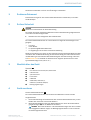
3 Überblick über das Gerät
Überblick:
A
!
Near Field Communication (NFC)-Schnittstelle
"
USB-Anschluss
§
Systemanschluss
$
Frontscheibe
%
STATE-LED
&
OSSD-LED (scanGrid2 I/O)
S
AFE OUT (scanGrid2 CANopen)
/
Befestigungsbohrungen
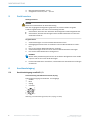
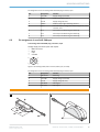
4 Gerät montieren
Sicherer Mehrstrahlscanner:
B
Der sichere Mehrstrahlscanner kann direkt an der Maschine montiert werden.
Vorgehensweise
1. Die Anschlussleitung auf der Rückseite des sicheren Mehrstrahlscanners je nach
Bedarf nach links oder nach rechts abführen.
2. Mit 2 M5-Schrauben den sicheren Mehrstrahlscanner durch die beiden Befesti‐
gungsbohrungen (!) an die Maschine schrauben.
HINWEIS Wenn die Vibrations- und Schockanforderungen über den im Daten‐
bla
tt angegebenen Werten liegen, die Befestigungsschrauben mit einem Schrau‐
bensicherungsmittel sichern.
MONTAGEANLEITUNG
8025966/2020-12-02 | SICK M O N T A G E A N L E I T U N G | scanGrid2 I/O, scanGrid2 CANopen
3
Irrtümer und Änderungen vorbehalten

3. Minimale Einschraubtiefe: 12 mm.
4.
Anzugsdrehmoment: 4,5 Nm … 5,0 Nm.
5 Gerät tauschen
Wichtige Hinweise
GEFAHR
G
efahr der Unwirksamkeit der Schutzeinrichtung
Falls eine ungeeignete Konfiguration gespeichert ist, wird der Gefahr bringende
Zustand möglicherweise nicht oder nicht rechtzeitig beendet.
b
Sicherstellen, dass nach dem Austausch die Konfiguration wiederhergestellt wird.
b
Sicherstellen, dass die Ausrichtung des sicheren Mehrstrahlscanners nach dem
Austausch korrekt ist.
Vorgehensweise
1.
Anschlussleitungen vom sicheren Mehrstrahlscanner lösen.
2. Befestigungsschrauben lösen und defekten sicheren Mehrstrahlscanner entfer‐
nen.
3. Den neuen sicheren Mehrstrahlscanner montieren.
4. Anschlussleitungen wieder am neuen sicheren Mehrstrahlscanner anbringen.
5. Den sicheren Mehrstrahlscanner konfigurieren.
HINWEIS
Mit der S
afety Assistant App können Sie die verifizierte Konfiguration eines Geräts
kopieren und auf ein neues Gerät übertragen.
6. Erneute Inbetriebnahme durchführen, insbesondere alle beschriebenen Prüfungen
dur
chführen.
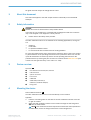
6 Anschlussbelegung
6.1 Anschlussbelegung scanGrid2 I/O
Anschlussleitung mit M12-Steckverbinder, 8-polig
Spannun
gsversorgung und lokale Ein- und Ausgänge
•
Stecker
•
M12
•
8-polig
•
A-codiert
7
6
8
5
4
2
3
1
Abbildung 1: Anschlussleitung (Stecker, M12, 8-polig, A-codiert)
MONTAGEANLEITUNG
4
M O N T A G E A N L E I T U N G | scanGrid2 I/O, scanGrid2 CANopen 8025966/2020-12-02 | SICK
Irrtümer und Änderungen vorbehalten

Anschlussbelegung der Anschlussleitung mit M12-Steckverbinder, 8-polig
Pin Bezeichnung Funktion
1 +24 V DC Versorgungsspannung (+24 V DC)
2 OSSD1 OSSD1 (Schaltausgang 1)
3 0 V DC Versorgungsspannung (0 V DC)
4 OSSD2 OSSD2 (Schaltausgang 2)
5 Uni-O Universalausgang, konfigurierbar: Überwachungsergeb‐
nis
, Verschmutzung, Fehler
6 IN 1 Steuereingang 1: Überwachungsfallumschaltung
7 IN 2 Steuereingang 2: Überwachungsfallumschaltung
8 IN 3 Steuereingang 3: Überwachungsfallumschaltung
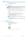
6.2 Anschlussbelegung scanGrid2 CANopen
Anschlussleitung mit M12-Steckverbinder, 5-polig
Spannun
gsversorgung und lokale Ein- und Ausgänge
•
Stecker
•
M12
•
5-polig
•
A-codiert
2 1
4
3
5
Abbildung 2: Anschlussleitung (Stecker, M12, 5-polig, A-codiert)
Ansc
hlussbelegung der Anschlussleitung mit M12-Steckverbinder, 5-polig
Pin Bezeichnung Funktion
1 CAN shield Abschirmung
2 +24 V DC Versorgungsspannung (+24 V DC)
3 0 V DC Versorgungsspannung (0 V DC)
4 CAN high CAN-Signal
5 CAN low CAN-Signal
A
&
%
$
/
§
"
!
B
!
MONTAGEANLEITUNG
8025966/2020-12-02 | SICK M O N T A G E A N L E I T U N G | scanGrid2 I/O, scanGrid2 CANopen
5
Irrtümer und Änderungen vorbehalten


All rights reserved. Subject to change without notice.
1 About this document
This document applies to the safe multiple scanner scanGrid2 I/O and scanGrid2
C
ANopen.
2 Safety information
DANGER
Hazard due to lack of effectiveness of the protective device
In the case of non-compliance, it is possible that the dangerous state of the machine
may not be stopped or not stopped in a timely manner.
b
Please observe the safety notes provided.
The safe multibeam scanner is not suitable for the following applications, among oth‐
er
s:
•
Outdoors
•
Underwater
•
In explosion-hazardous areas
•
In environments with increased levels of ionizing radiation
For more information about how to work with the protective device, refer to the machin‐
ery documentation or the operating instructions for the protective device. You can call
up the EU declaration of conformity and the current operating instructions for the
protective device by entering the part number in the search field at www.sick.com (part
number: see the type label entry in the “Ident. no.” field).
3 Device overview
Overview:
A
!
Near Field Communication (NFC) interface
"
USB connection
§
System connection
$
Front screen
%
STATE LED
&
OSSD LED (scanGrid2 I/O)
S
AFE OUT (scanGrid2 CANopen)
/
Fixing holes
4 Mounting the device
Safe multibeam scanner:
B
The safe multibeam scanner can be mounted directly on the machine.
Approach
1. Lead the connecting cable on the back of the safe multibeam scanner to the left
or right as needed.
2. Screw the safe multibeam scanner to the machine through the two fixing holes
(!) with the 2 M5 screws.
NOTE If the vibration and shock requirements exceed the values specified in
t
he data sheet, secure the fixing screws with a screw locking device.
MOUNTING INSTRUCTIONS
8025966/2020-12-02 | SICK M O U N T I N G I N S T R U C T I O N S | scanGrid2 I/O, scanGrid2 CANopen
7
Subject to change without notice

3. Minimum depth of thread: 12 mm.
4.
Tightening torque: 4.5 Nm … 5.0 Nm.
5 Replacing the device
Important information
DANGER
H
azard due to lack of effectiveness of the protective device
If an unsuitable configuration has been saved, it may cause the dangerous state to not
end in time.
b
Make sure that the configuration is restored after replacing the device.
b
Make sure that the safe multibeam scanner is aligned correctly after replacing the
device.
Approach
1.
Disconnect the connecting cables to the safe multibeam scanner.
2. Unscrew the fixing screws and remove the defective safe multibeam scanner.
3. Mount the new safe multibeam scanner.
4. Reconnect the connecting cables to the new safe multibeam scanner.
5. Configure the safe multibeam scanner.
NOTE
Y
ou can use the Safety Assistant app to copy the verified configuration of a device
and transfer it to a new device.
6. Perform commissioning again, taking particular care to conduct all of the thorough
c
hecks described.
6 Pin assignment
6.1 Pin assignment of scanGrid2 I/O
Connecting cable with M12 plug connector, 8-pin
V
oltage supply and local inputs and outputs
•
Male connector
•
M12
•
8-pin
•
A-coded
7
6
8
5
4
2
3
1
Figure 1: Connecting cable (male connector, M12, 8-pin, A-coded)
MOUNTING INSTRUCTIONS
8
M O U N T I N G I N S T R U C T I O N S | scanGrid2 I/O, scanGrid2 CANopen 8025966/2020-12-02 | SICK
Subject to change without notice

Pin assignment of the connecting cable with M12 plug connector, 8-pin
PIN Designation Function
1 +24 V DC Supply voltage (+24 V DC)
2 OSSD1 OSSD1 (switching output 1)
3 0 V DC Supply voltage (0 V DC)
4 OSSD2 OSSD2 (output signal switching device 2)
5 Uni-O Universal output, configurable: Monitoring result, conta‐
mina
tion, error
6 IN 1 Control input 1: Monitoring case switching
7 IN 2 Control input 2: Monitoring case switching
8 IN 3 Control input 3: Monitoring case switching
6.2 Pin assignment of scanGrid2 CANopen
Connecting cable with M12 plug connector, 5-pin
V
oltage supply and local inputs and outputs
•
Male connector
•
M12
•
5-pin
•
A-coded
2 1
4
3
5
Figure 2: Connecting cable (male connector, M12, 5-pin, A-coded)
P
in assignment of the connecting cable with M12 plug connector, 5-pin
PIN Designation Function
1 CAN shield Shielding
2 +24 V DC Supply voltage (+24 V DC)
3 0 V DC Supply voltage (0 V DC)
4 CAN HIGH CAN signal
5 CAN LOW CAN signal
A
&
%
$
/
§
"
!
B
!
MOUNTING INSTRUCTIONS
8025966/2020-12-02 | SICK M O U N T I N G I N S T R U C T I O N S | scanGrid2 I/O, scanGrid2 CANopen
9
Subject to change without notice

10
M O N T A G E A N L E I T U N G | scanGrid2 I/O, scanGrid2 CANopen 8025966/2020-12-02 | SICK
Irrtümer und Änderungen vorbehalten

8025966/2020-12-02 | SICK M O N T A G E A N L E I T U N G | scanGrid2 I/O, scanGrid2 CANopen
11
Irrtümer und Änderungen vorbehalten

SICK AG | Waldkirch | Germany | www.sick.com
8025966/2020-12-02/de/de, en
-
 1
1
-
 2
2
-
 3
3
-
 4
4
-
 5
5
-
 6
6
-
 7
7
-
 8
8
-
 9
9
-
 10
10
-
 11
11
-
 12
12


SICK scanGrid2 safe multibeam scanner Mounting instructions
- Typ
- Mounting instructions
in anderen Sprachen
Verwandte Papiere
-
SICK Multi Sensor Connector Mounting instructions
-
-
-
-
-
-
-
-
-